Ed Nisley's Blog: Shop notes, electronics, firmware, machinery, 3D printing, laser cuttery, and curiosities. Contents: 100% human thinking, 0% AI slop.
The burner in our oven failed in December 2006, probably because the charred remains of an insect produced a hotspot:
Burned Oven Tube Overview
That replacement burner came with its own igniter that failed after 8.5 years, with symptoms of slow oven ignition and the occasional smell of propane.
In normal operation, the igniter element glows yellow-hot for a minute or so before the valve opens, gas flows over the igniter, there’s a muffled whoomf, and the oven begins heating. The igniter remains powered as long as the oven is on, emitting a baleful yellow glare through the slots in the oven’s lower cover.
It consists of a ceramic base holding a stout resistance heater that apparently suffers from increasing resistance as it ages, reducing the current to the point where it won’t activate the gas valve.
I didn’t know that, either, but Google sees all, knows all, and tells most.
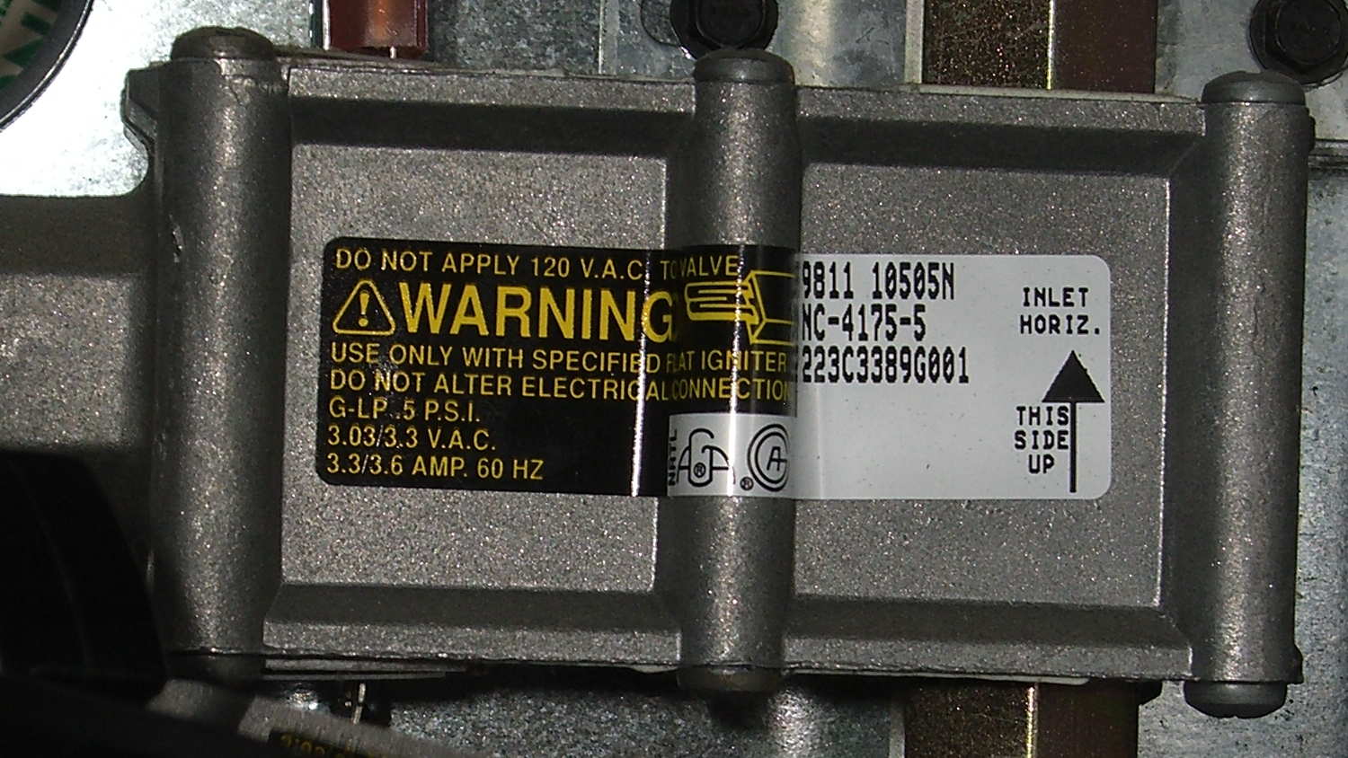
The gas valve label says it requires 3.3 to 3.6 A from the heater to turn on the gas:
Kenmore range oven gas valve – data plate
But the old heater was good for barely 2.6 A (there’s a bit of parallax in this view):
Kenmore range oven gas valve – weak igniter current
Igniters range from $18 to upwards of $60 on Amazon, so I picked the cheapest one, waited two days, installed it, and measured 3.5 A at First Light, down to a bit over 3.0 A at running temperature. That’s on the low side of the valve’s spec, but it seems happier with an extra half amp.
We’ll see how long this igniter lasts; maybe next time I’ll double my spend…
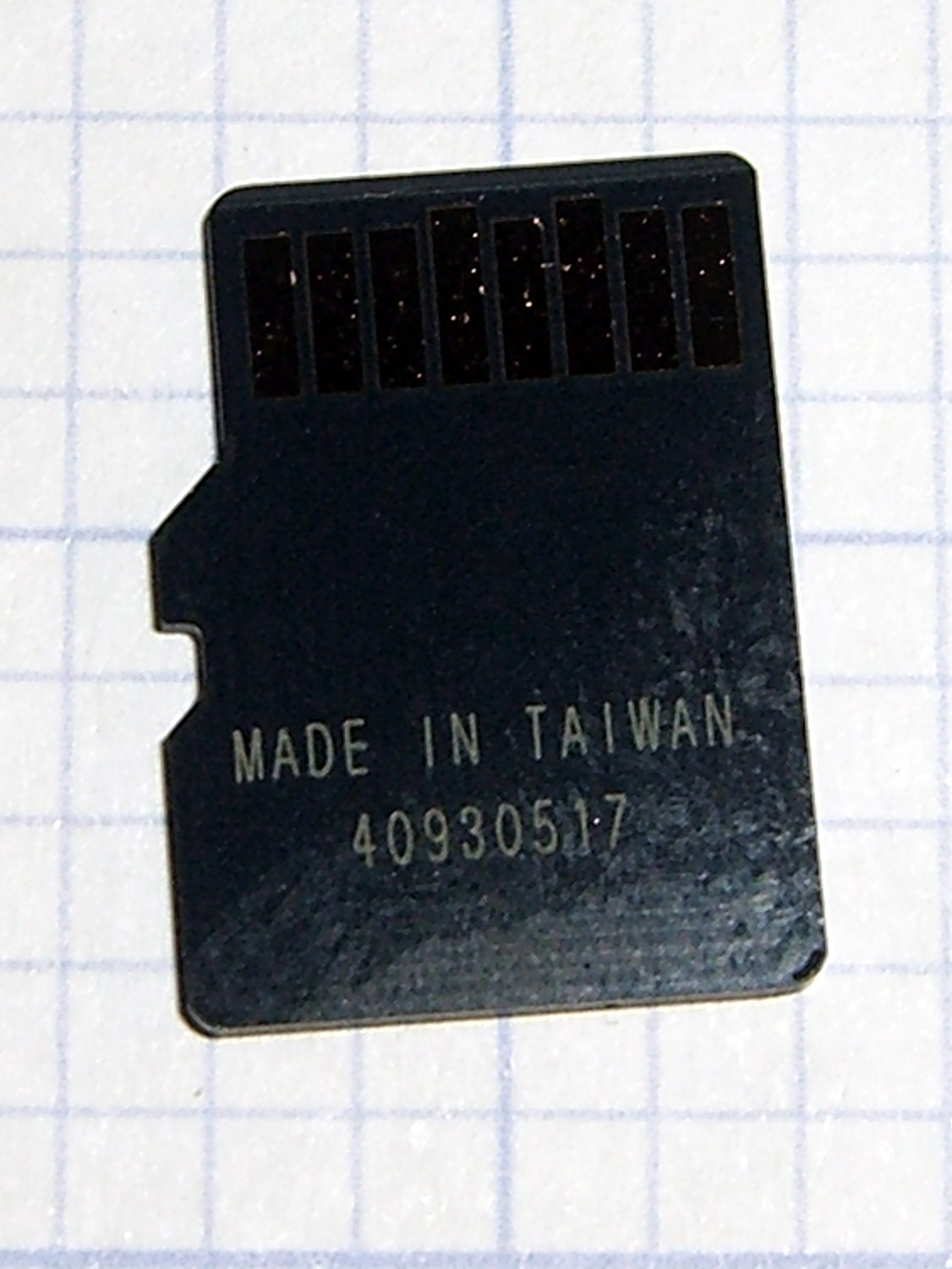
The previous cards were made in Korea, but this one came from Taiwan with a different serial number format:
Sony SR-64UX 64 GB MicroSDXC card – back
The tiny letters on the front identify it as an SR-64UX, but I haven’t been able to find any definitive Sony source describing the various cards; their catalog page listing cards for digital still cameras may be as good as it gets. This one seems to have a higher read speed, for whatever little good that may do.
It stored and regurgitated the usual deluge of video files with no problem, which is only to be expected. This time around, I checked the MD5 sums, rather than unleashing diff on the huge files:
cd /media/ed/9C33-6BBD/
for f in * ; do find /mnt/video/ -name $f | xargs md5sum $f ; done
11e31c9ba3befbef6dd3630bb68064d6 MAH00539.MP4
11e31c9ba3befbef6dd3630bb68064d6 /mnt/video/2015-07-05/MAH00539.MP4
... snippage ...
It now sits in the fancy plastic display case that the HDR-AS30V camera came in until the previous replacement card fails.
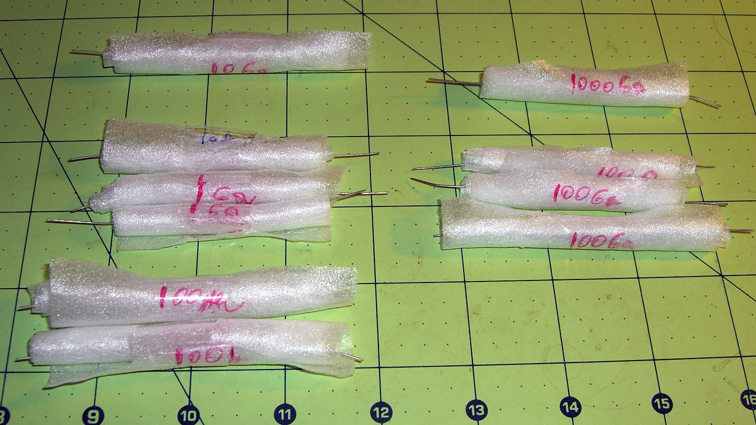
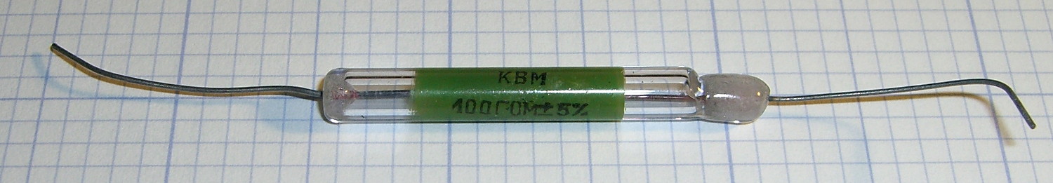
They’re glass electrometer resistors from late in the Cold War:
Russian 100 G electrometer resistor
That one presents 100 GΩ between its lead wires, which would count as open in any other circuit I’ve ever built.
The assortment arrived much richer than advertised, although I’d be even happier with a few more 10 GΩ and a few less 100 MΩ resistors. The 1000 GΩ = 1 TΩ resistor in the upper right seems absurd on the face of it, but there it sits.
I have no way to measure these, other than to build an electrometer amp and see what happens…
Given the ionization chamber’s tiny currents and the huge resistors required to turn them into voltages, reviewing the thermal noise I generally ignore seems in order…
The RMS noise voltage of an ordinary resistor:
vn = √ (4 kB T R Δf)
The constants:
kB – Boltzman’s Constant = 1.38×10⁻²³ J/K
T – temperature in kelvin = 300 K (close enough)
Mashing them together:
vn = √ (16.6x10⁻²¹ R Δf)
vn = 129x10-12 √ (R Δf)
For a (generous) pulse current of 20 fA, a 10 GΩ resistor produces a mere 200 μV, so wrap a gain of 100 around the op amp to get 20 mV. An LMC6081 has a GBW just over 1 MHz, giving a 10 kHz bandwidth:
vn = 129x10-12 √ (10x109 10x103) = 1.3 mV
Which says the noise will be loud, but not deafening.
A 100 GΩ resistor increases the voltage by a factor of 10, so you can decrease the gain by a factor of ten for the same 20 mV output, which increases the bandwidth by a factor of ten, which increases the noise by a factor of … ten.
Ouch.
With the same gain of 100 (and therefore 10 kHz bandwidth) after the 100 GΩ resistor, the output increases by a factor of ten to 200 mV, but the noise increases by only √10 to 4 mV.
The LMC6081 has 22 nV/√Hz and 0.2 fA/√Hz input-referred noise, neither of which will rise above the grass from the resistor.
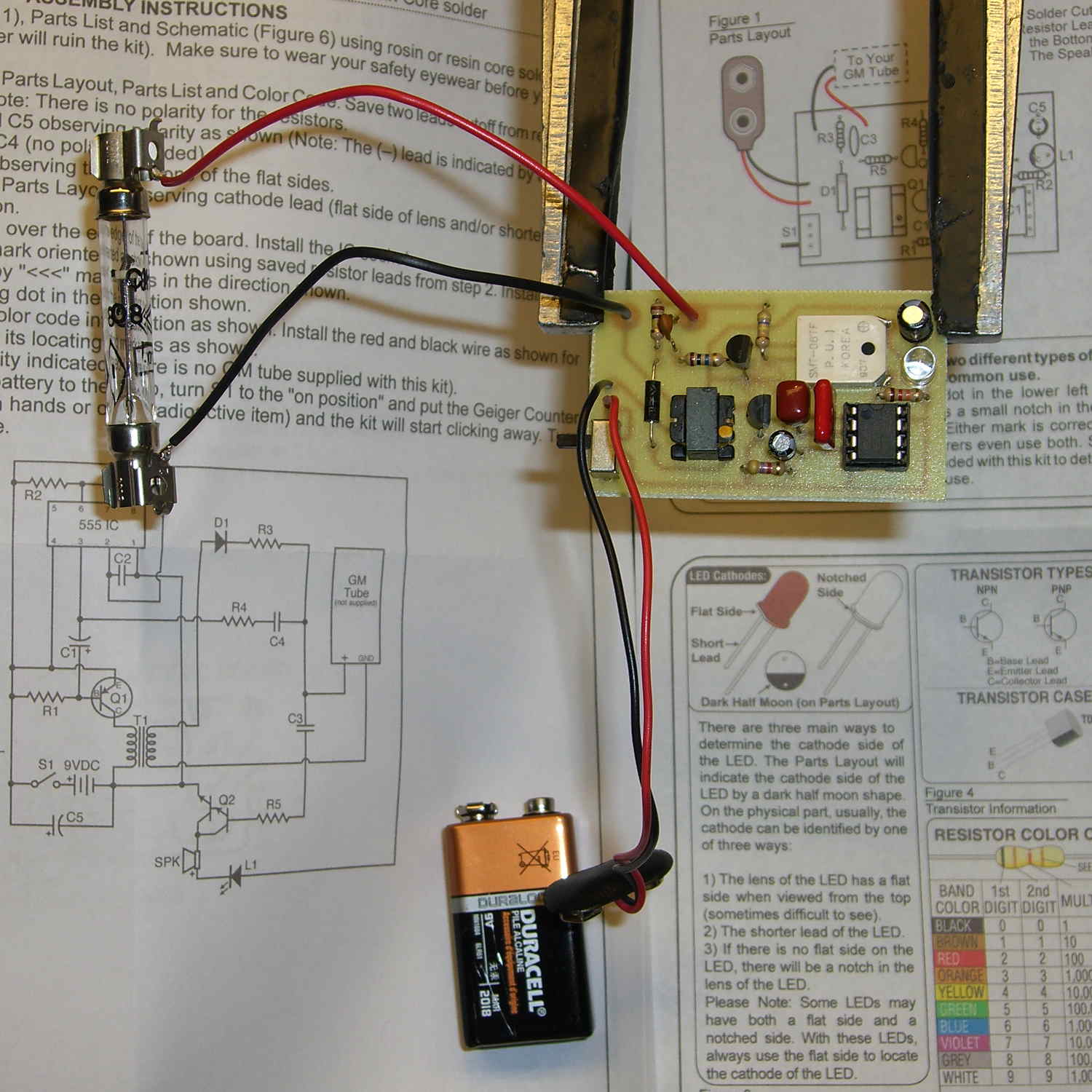
It’s a good thing I have a pretty deep parts stock, as one of the caps didn’t fit into its holes at all.
The Russian CI-3BG glass tube, according to the datasheet and discussion on MightyOhm, is sensitive to gamma and beta radiation, so it should serve as a simple cross-check on my ionization chamber results. It’s not clear the C8600 is applying the correct voltage to the CI-3BG tube, but it probably doesn’t make much difference; the supply is so feeble that there’s no way to actually measure the results.
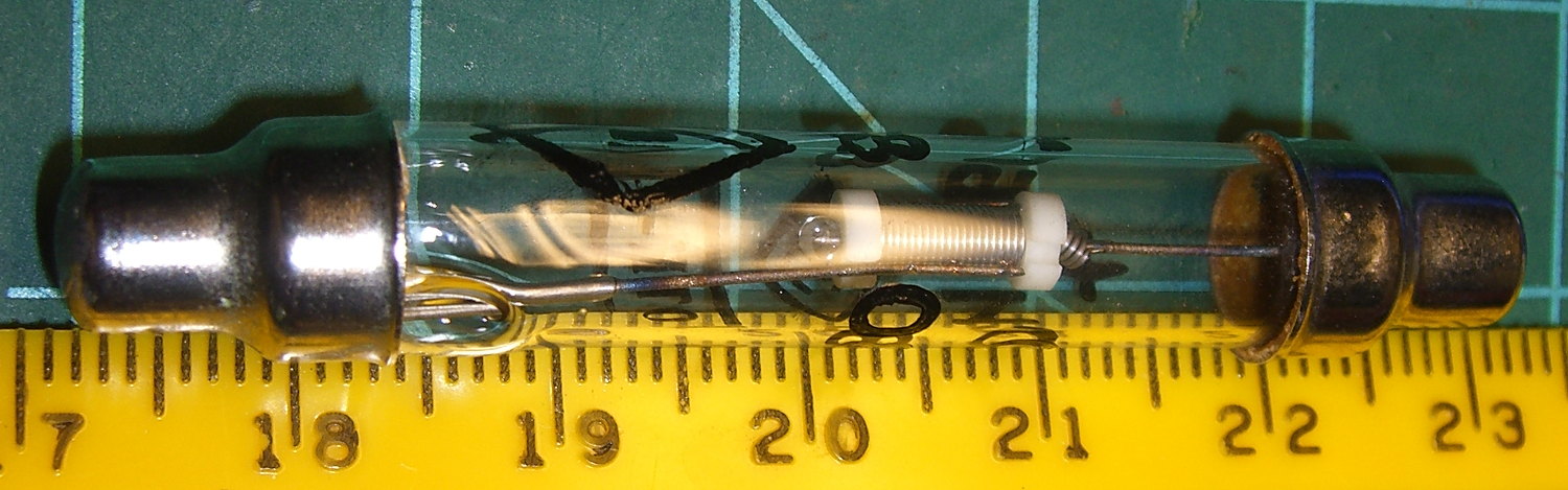
A closer look at the CI-3BG suggests the active volume lies inside that spiral-wrapped section between the white insulators:
Russian CI-3BG Glass Geiger Tube – detail
In round numbers, that section is 6 mm long and 3 mm OD. Figuring the ID at 2.5 mm, that’s a volume of 30 mm3 = 0.030 cm3. That’s maybe 1/7300 of the ionization chamber volume, so, (handwaving) assuming roughly equal sensitivity, the chamber should report three orders of magnitude more pulses than this little thing.
It’s mildly sensitive to a radium-dial watch and perks up when a watch hand lines up along the spiral-wrapped volume. Given that the radium decay sequence spits out betas and no gammas, the (scaled) count may be a bit higher than the ionization chamber produces, but there are so many other imponderables that it might not matter in the least.
Feeding the output voltage into the ‘scope, with AC coupling to strip off the DC bias, produces this:
Darlington 12k load – multiple
Those cute little spikes seem to be gamma ray ionization events: they are always positive-going, there are no similar negative-going pulses, they occur irregularly at a few per second with occasional clusters, and generally seem about like random radioactive events. The picture shows a particularly busy interval; mostly, nothing happens and the baseline voltage wobbles around in a low frequency rumble.
For what it’s worth, the shielding around the circuit completely eliminates not only 60 Hz interference, but everything else, too: astonishingly good results from a fairly simple layout.
Taking a closer look at one pulse:
Darl 12k – single detail
(Vigorous handwaving begins)
The tallest spikes are typically 20 mV above the baseline, corresponding to peak output current of 20 mV / 12 kΩ = 1.5 µA and a chamber current of 1.5 µA / 100×106 = 15 fA.
They’re generally 5 ms wide, which is orders of magnitude longer than the actual ion generation time, but the area under that spike should be more-or-less proportional to the area under the actual impulse.
If you grant that and agree those pulses look mostly triangular, their integral is:
1/2 x 15 fA x 5 ms = 40 fA·ms = 40 aC
That’s “a” for “atto” =10-18 = a billionth of a billionth = hardly anything at all.
Indeed, seeing as how one coulomb contains 6.2×10¹⁸ electron charges, that pulse represents 250 ion pairs, at least assuming a zero-current baseline.
Gamma rays arrive with various energies, produce ionization trails of various lengths, and don’t necessarily traverse the entire chamber, so the pulses have various heights & widths; you can see smaller pulses sticking up out of the grass in the first scope shot. Assuming all those average out to five “big” pulses every second, the chamber collector electrode passes 200 aC/s into the transistor base → 200 aA → 0.20 fA. At 1 fA per 100 µR/h, that’s 20 µR/h of gamma background.
Working from the other end of the scale, a bit of searching shows that 1 R produces 2.08×10⁹ ion pairs in 1 cm3 of dry air at STP. The ionization chamber dimensions give the can’s volume:
π x 4.52 x 3.5 = 220 cm3
So assuming a somewhat unreasonably large pure-gamma dose of 10 µR/h in that volume will produce:
10x10-6 x 2.08x109 x 220 = 4600x103 ion pairs/h = 1300 ion pairs/s
That’s about five “big pulses” per second, under the stack of assumptions thus far, and seems absurdly close.
An old NIST report on Calibration of X-Ray and Gamma-Ray Measuring Instruments says that 1 R/s (that’s per second, not per hour) produces a current of 300 pA/cm3 in an “ideal ionization chamber”. Scaling that down to 10 µR/h and up to the chamber volume gives an average current of 180 aA. That’s absurdly close, too.
Note bene: Because 1 C = 6.241×10¹⁸ ion pairs, 2.08×10⁹ ion pairs is 333×10-12 C and, if you do that in one second, you get 333 pA of current from your ideal 1 cm3 ionization chamber. Those two approaches should be equally close.
(Vigorous handwaving ends)
Again, I don’t trust any of the values to within an order of magnitude and surely made a major blunder in running some of the numbers, but the results seem encouraging.
The coaxial cable’s capacitance could explain why the pulses look like triangles: the capacitance integrates a rectangular current pulse into a voltage ramp. The cable measures 200 pF and the scope input adds 13 pF, but let’s call it 200 pF across the 12 kΩ emitter resistor. Raising the voltage across that capacitance by 20 mV in 2 ms requires a current of:
200x10-12 x (20 mV / 2 ms) = 2 nA
Dividing that by 100×106 gives a chamber current pulse of 20×10-18 = 20 aA: three orders of magnitude less than the original guesstimate. That suggests the (handwaved) 15 fA chamber current, amplified by the absurd gain of two stacked Darlingtons, easily drives the cable capacitance. Something else causes the ramp.
The chamber itself has 10 pF capacitance, but it’s not clear to me how (or if) that enters into the proceedings. The entire collection of ions appears in mid-air, as if by magic, whereupon the +24 V chamber bias voltage draws them (well, the positive ones, anyway) to the transistor base without appreciable voltage change.
Perhaps the triangle represents the actual arrival of the ions: a few at first from the near side of the trail, a big bunch from the main trail, stragglers from the far side, then tapering off back to the baseline.
That’s definitely more than anyone should infer from a glitch produced by a pair of transistors…