Ed Nisley's Blog: Shop notes, electronics, firmware, machinery, 3D printing, laser cuttery, and curiosities. Contents: 100% human thinking, 0% AI slop.
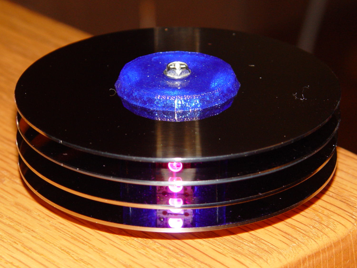
About a week after First Light, one of the knockoff Neopixels (not a Genuine Adafruit Product) suffered an intermittent failure: it worked fine after being off for an hour or two, but eventually stalled at a fixed color, with all downstream pixels equally dead. Of course, it was the middle package in the string of three, buried in the hub (this is before the failure):
Hard Drive Mood Light – low angle
Spraying circuit cooler on the package brought it back to life for a few minutes, confirming the diagnosis. Reducing the maximum intensity to PWM 32 reduced the average power dissipation enough to let it run for as long as I was willing to let it, although it might not survive a hot summer day.
Not having glued the spacers onto the hub simplified extracting the strip, although warranty repair is always a nuisance. I daubed red Sharpie on the failing LED to avoid losing track of it, then resoldered the LED and capacitor connections to no avail:
Knockoff Neopixel Failure – overview
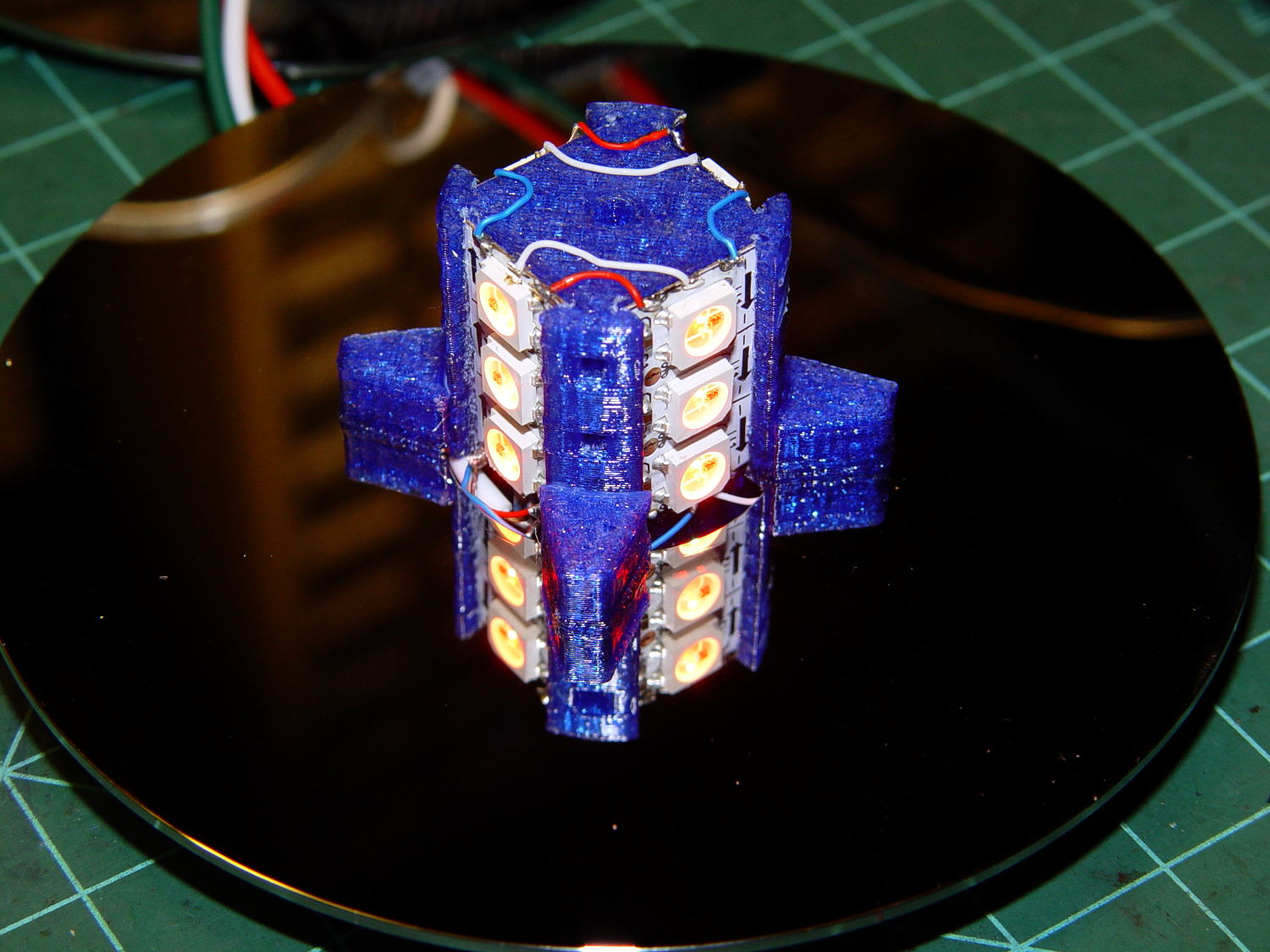
There’s nothing obviously wrong inside:
Knockoff Neopixel Failure – detail
The fine details of the WS2812B controller produce a horrible Moiré blur with the camera’s low-res image, but you get the general idea.
Most likely, one of those flying wires isn’t quite bonded, but we’ll never know…
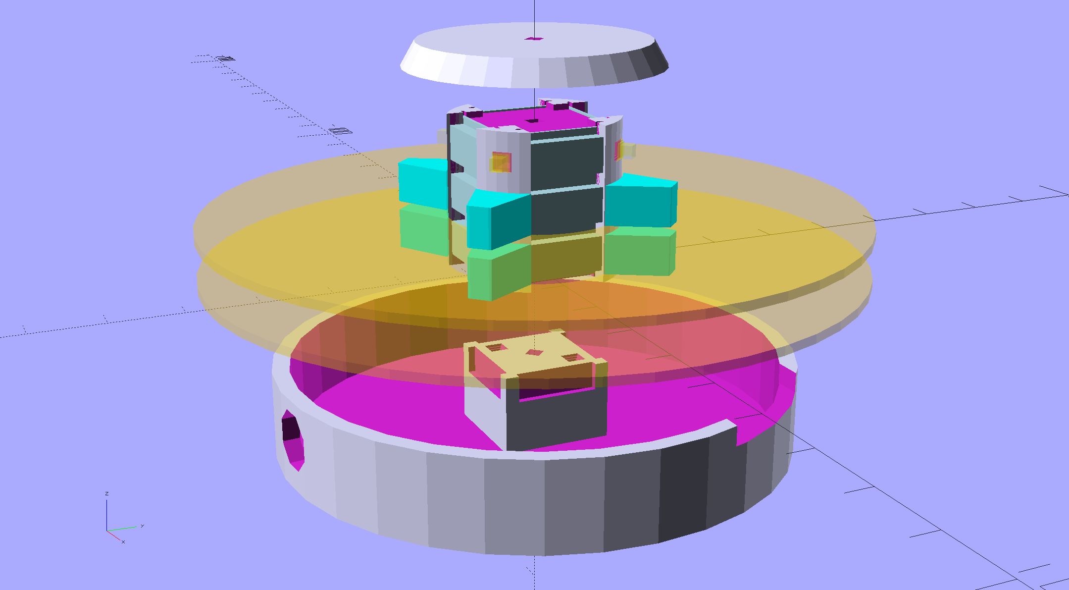
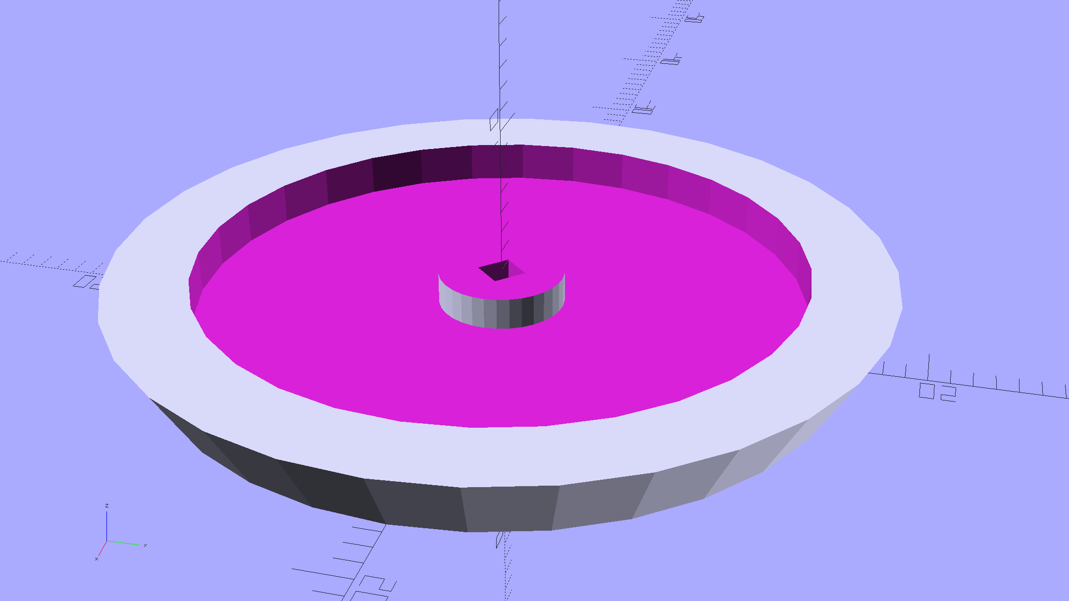
An improved version of the 3D printed plastic bits going into the Hard Drive Platter Mood Light:
Hard Drive Mood Light – improved – solid model – Show view
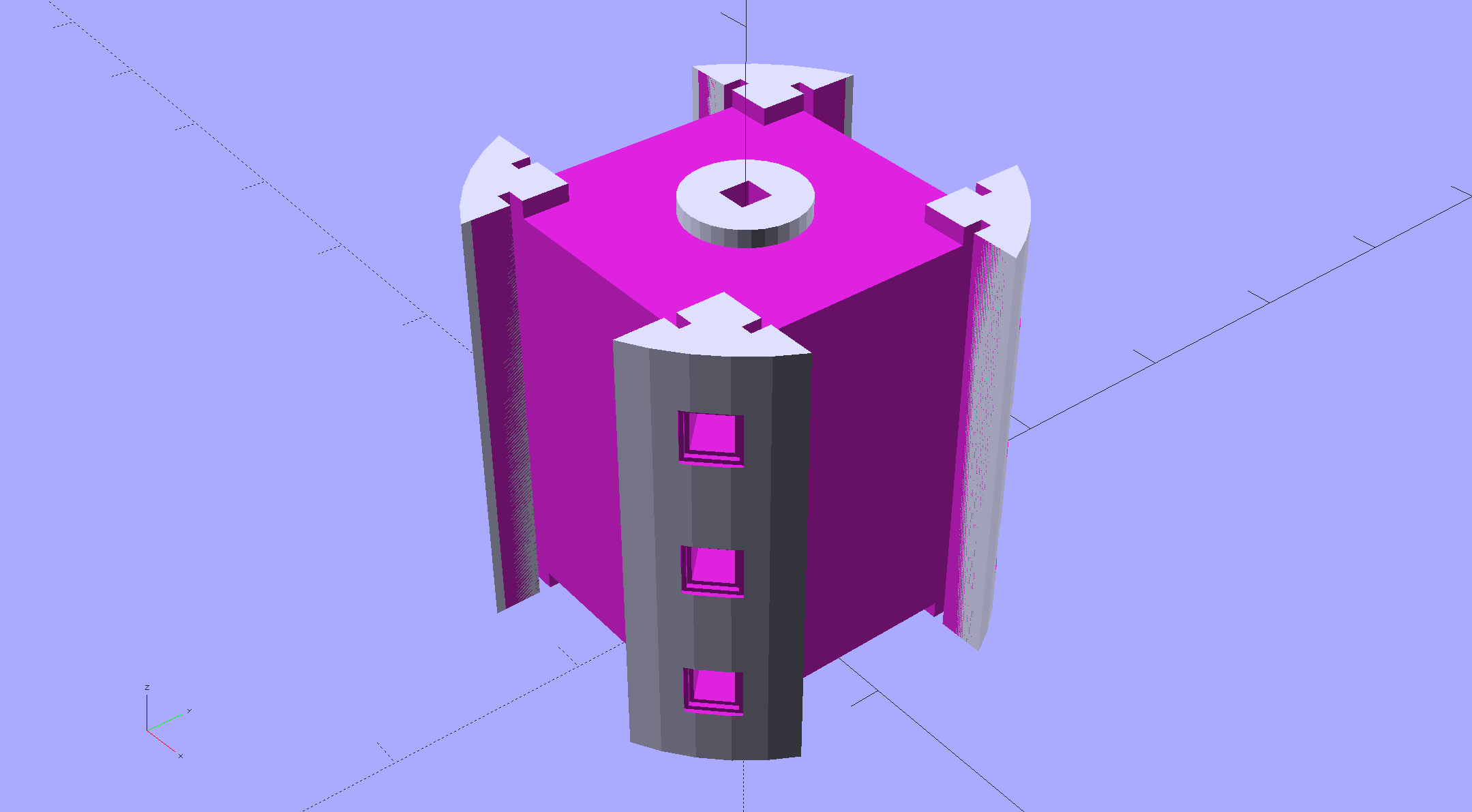
The central pillar now has cutouts behind the Neopixel strips so you (well, I) can solder directly to the larger half-pads on the back, plus a boss on the top for better wire management:
Hard Drive Mood Light – improved – Pillar – solid model
I’m not entirely satisfied with the little slots for the strip edges; the resolution limits of 3D printing call for larger openings, but there’s not much meat around those pins up the edge.
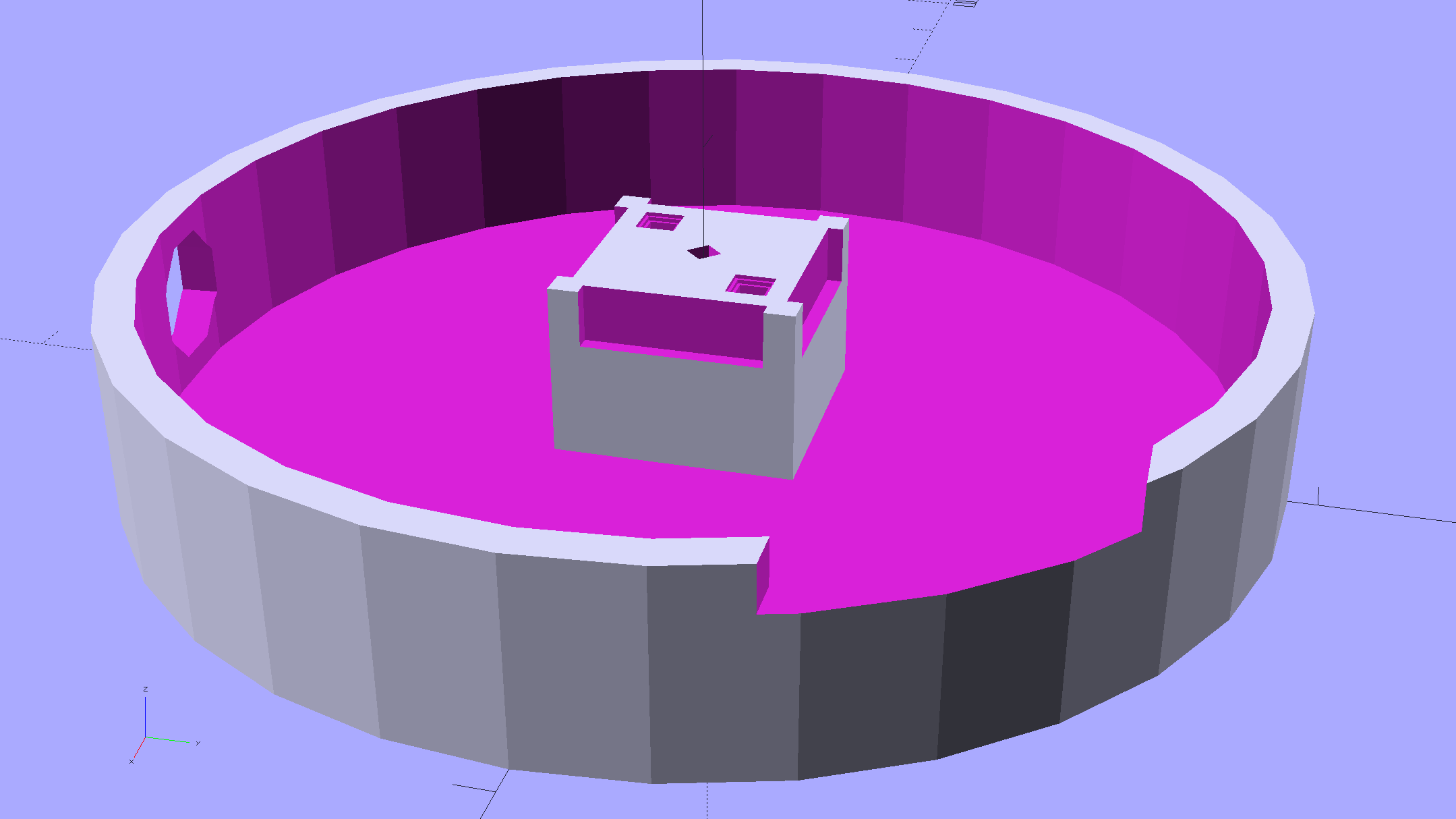
The base becomes much larger to hold the Arduino Pro Mini and gains an optional slot to let the programming cable reach the outside:
Hard Drive Mood Light – improved – Base – solid model
The cap has a boss matching the one atop the pillar:
Hard Drive Mood Light – improved – Cap – solid model
Both the cap & base have center features recessed by two thread thicknesses to let their rims apply a slight clamping force on the platters.
Our Larval Engineer says it really needs an internal battery with maybe four hours of runtime, a charging base station (ideally with inductive power transfer), buttons (or, better, a tilt switch / accelerometer) for mode selection, and perhaps a microphone to synchronize lighting effects with music. To my horror, her co-op job seems to have exposed her to Marketeers…
We do, however, agree that the Cap would look better in lathe-turned brass with a non-tarnish clearcoat.
The OpenSCAD source code:
// Hard Drive Platter Mood Light
// Ed Nisley KE4ZNU November 2015

Layout = "Spacers";					// Build Show Pixel LEDString Platters Pillar Spacers TopCap Base

CablePort = true;

ShowDisks = 2;						// number of disks in Show layout

//- Extrusion parameters must match reality!

ThreadThick = 0.25;
ThreadWidth = 0.40;

HoleWindage = 0.2;

Protrusion = 0.1;			// make holes end cleanly

inch = 25.4;

function IntegerMultiple(Size,Unit) = Unit * ceil(Size / Unit);

//----------------------
// Dimensions

ID = 0;
OD = 1;
LENGTH = 2;

Platter = [25.0,95.0,1.27];						// hard drive platters - must match actual thickness!

LEDStringCount = 3;								// number of LEDs on each strip
LEDStripCount = 4;								// number of strips (verify locating pin holes & suchlike)

WireSpace = 1.0;								// allowance for wiring along strip ends

Pixel = [13.0, 1000 / 144, 0.6];				// smallest indivisible unit of LED strip
PixelMargin = [1.0, 1.0, 2.0];					// LED and circuitry atop the strip

BeamAngle = 120;								// LED viewing angle
BeamShape = [
	[0,0],
	[Platter[OD]*cos(BeamAngle/2),-Platter[OD]*sin(BeamAngle/2)],
	[Platter[OD]*cos(BeamAngle/2), Platter[OD]*sin(BeamAngle/2)]
];

PillarSides = 12*4;

PillarCore = Platter[ID] - 2*(Pixel[2] + PixelMargin[2] + 2.0);		// LED channel distance across pillar centerline
PillarLength = LEDStringCount*Pixel[1] + Platter[LENGTH];
echo(str("Pillar core size: ",PillarCore));
echo(str("      ... length:"),PillarLength);

PCB = [34.5,17.5,1.6];								// Arduino Pro Mini (or whatever) PCB size
PCBClearTop = 5.0;
PCBClearBot = 5.0;
PCBHeight = PCB[2] + PCBClearBot + PCBClearTop;

PCBRadius = sqrt(pow(Platter[ID]/2 + PCB[1],2) + pow(PCB[0]/2,2));
echo(str("PCB Corner radius: ",PCBRadius));

CoaxConn = [7.8,11.2,5.0];							// power connector

Cap = [Platter[ID] + 4.0,Platter[ID] + 4.0 + 10*2*ThreadWidth,2*WireSpace + 6*ThreadThick];		// cap over top of pillar
CapSides = 8*4;

BaseClearHeight = max(PCBHeight,CoaxConn[OD]);

Base = [2.0 + 2*PCBRadius,2.0 + 2*PCBRadius + CoaxConn[LENGTH],BaseClearHeight + 6*ThreadThick];
BaseSides = 8*4;

Screw = [1.5,2.0,20.0];							// screws used to secure cap & pillar

Spacer = [Platter[ID],(Platter[ID] + 2*8),(Pixel[1] - Platter[LENGTH])];
echo(str("Spacer  OD: ",Spacer[OD]));
echo(str(" ... thick:",Spacer[LENGTH]));

LEDStripProfile = [
	[0,0],
	[Pixel[0]/2,0],
	[Pixel[0]/2,Pixel[2]],
	[(Pixel[0]/2 - PixelMargin[0]),Pixel[2]],
	[(Pixel[0]/2 - PixelMargin[0]),(Pixel[2] + PixelMargin[2])],
	[-(Pixel[0]/2 - PixelMargin[0]),(Pixel[2] + PixelMargin[2])],
	[-(Pixel[0]/2 - PixelMargin[0]),Pixel[2]],
	[-Pixel[0]/2,Pixel[2]],
	[-Pixel[0]/2,0]
];

//----------------------
// Useful routines

module PolyCyl(Dia,Height,ForceSides=0) {			// based on nophead's polyholes

  Sides = (ForceSides != 0) ? ForceSides : (ceil(Dia) + 2);

  FixDia = Dia / cos(180/Sides);

  cylinder(r=(FixDia + HoleWindage)/2,
		h=Height,
	$fn=Sides);
}

//- Locating pin hole with glue recess
//  Default length is two pin diameters on each side of the split

PinOD = 1.70;

module LocatingPin(Dia=PinOD,Len=0.0) {

	PinLen = (Len != 0.0) ? Len : (4*Dia);

	translate([0,0,-ThreadThick])
		PolyCyl((Dia + 2*ThreadWidth),2*ThreadThick,4);

	translate([0,0,-2*ThreadThick])
		PolyCyl((Dia + 1*ThreadWidth),4*ThreadThick,4);

	translate([0,0,-(PinLen/2 + ThreadThick)])
		PolyCyl(Dia,(PinLen + 2*ThreadThick),4);

}
//----------------------
// Pieces

//-- LED strips

module OnePixel() {

	render()
		rotate([-90,0,0]) rotate(180)				// align result the way you'd expect from the dimensions
			difference() {
				linear_extrude(height=Pixel[1],convexity=3)
					polygon(points=LEDStripProfile);
				translate([-Pixel[0]/2,Pixel[2],-PixelMargin[0]])
					cube([Pixel[0],2*PixelMargin[2],2*PixelMargin[0]]);
				translate([-Pixel[0]/2,Pixel[2],Pixel[1]-PixelMargin[0]])
					cube([Pixel[0],2*PixelMargin[2],2*PixelMargin[0]]);
			}
}

module LEDString(n = LEDStringCount) {

	for (i=[0:n-1])
		translate([0,i*Pixel[1]])
//			resize([0,Pixel[1] + 2*Protrusion,0])
				OnePixel();
}

//-- Stack of hard drive platters

module Platters(n = LEDStringCount + 1) {

	color("gold",0.4)
	for (i=[0:n-1]) {
		translate([0,0,i*Pixel[1]])
			difference() {
				cylinder(d=Platter[OD],h=Platter[LENGTH],center=false,$fn=PillarSides);
				cylinder(d=Platter[ID],h=3*Platter[LENGTH],center=true,$fn=PillarSides);
			}
	}
}

//-- Pillar holding the LED strips

module Pillar() {

	difflen = PillarLength + 2*Protrusion;

//	render(convexity=5)
	difference() {
		linear_extrude(height=PillarLength,convexity=4)
			difference() {
				rotate(180/(12*4))
					circle(d=Platter[ID] - 1*ThreadWidth,$fn=PillarSides);

				for (i=[0:LEDStripCount-1]) 					// clearance for LED beamwidth, may not actually cut surface
					rotate(i*360/LEDStripCount)
						translate([PillarCore/2,0,0])
							polygon(points=BeamShape);

				for (i=[0:LEDStripCount-1])						// LED front clearance
					rotate(i*360/LEDStripCount)
						translate([(PillarCore/2 + Pixel[2]),(Pixel[0] - 2*PixelMargin[0])/2])
							rotate(-90)
								square([Pixel[0] - 2*PixelMargin[0],Platter[ID]]);

			}

		for (i=[0:LEDStripCount-1])								// LED strip slots
			rotate(i*360/LEDStripCount)
				translate([PillarCore/2,0,-Protrusion])
					linear_extrude(height=difflen,convexity=2)
						rotate(-90)
							polygon(points=LEDStripProfile);

		difference() {											// wiring recess on top surface, minus boss
			for (i=[0,90])
				rotate(i)
					translate([0,0,(PillarLength - (WireSpace/2 - Protrusion))])
						cube([(PillarCore + 2*Protrusion),Pixel[0] - 2*PixelMargin[0],WireSpace],center=true);
			cylinder(d=3*Screw[OD],h=PillarLength + Protrusion,$fn=CapSides);
		}

		for (i=[0:LEDStripCount-1])								// wiring recess on bottom surface
			rotate(i*90)
				translate([PillarCore/2 - (WireSpace - Protrusion)/2,0,WireSpace/2 - Protrusion])
					cube([WireSpace + Protrusion,Pixel[0] - 2*PixelMargin[0],WireSpace],center=true);

		for (j=[0:LEDStringCount-1])							// platter spacer alignment pins
			for (i=[0:LEDStripCount-1])
				rotate(i*360/LEDStripCount + 180/LEDStripCount)
					translate([(Platter[ID] - 1*ThreadWidth)/2,0,(j*Pixel[1] + Pixel[1]/2 + Platter[LENGTH]/2)])
						rotate([0,90,0])
							rotate(45)
								LocatingPin();

		translate([0,0,-Protrusion])							// central screw hole
			rotate(180/4)
				PolyCyl(Screw[ID],difflen,4);

		if (false)
		for (i=[-1,1])											// vertical wire channels
			rotate(i*360/LEDStripCount + 180/LEDStripCount)
				translate([PillarCore/2 - 2.0,0,-Protrusion])
					PolyCyl(2.0,difflen,4);

		for (i=[-1,1])											// locating pins
			rotate(i*360/LEDStripCount - 180/LEDStripCount)
				translate([PillarCore/2 - 2.0,0,0])
					LocatingPin();
	}
}

//-- Spacers to separate platters

module Spacers() {

	difference() {
		linear_extrude(height=Spacer[LENGTH],convexity=4)
			difference() {
				rotate(180/PillarSides)
					circle(d=Spacer[OD],$fn=PillarSides);

				for (i=[0:LEDStripCount-1]) 					// clearance for LED beamwidth, may not actually cut surface
					rotate(i*360/LEDStripCount)
						translate([PillarCore/2,0,0])
							polygon(points=BeamShape);

				for (i=[0:LEDStripCount-1])						// LED front clearance
					rotate(i*360/LEDStripCount)
						translate([(PillarCore/2 + Pixel[2]),(Pixel[0] - 2*PixelMargin[0])/2])
							rotate(-90)
								square([Pixel[0] - 2*PixelMargin[0],Platter[ID]]);


				rotate(180/PillarSides)
					circle(d=Spacer[ID],$fn=PillarSides);		// central pillar fits in the hole
			}

		for (i=[0:LEDStripCount-1])
			rotate(i*360/LEDStripCount + 180/LEDStripCount)
				translate([Platter[ID]/2,0,(Pixel[1] - Platter[LENGTH])/2])
					rotate([0,90,0])
						rotate(45)
							LocatingPin();

	}
}

//-- Cap over top of pillar

module TopCap() {

	difference() {
		cylinder(d1=(Cap[OD] + Cap[ID])/2,d2=Cap[OD],h=Cap[LENGTH],$fn=CapSides);		// outer lid

		translate([0,0,-Protrusion])
			PolyCyl(Screw[ID],Cap[LENGTH] + WireSpace + Protrusion,4);					// screw hole

		translate([0,0,Cap[LENGTH] - 2*WireSpace])
			difference() {
				cylinder(d=Cap[ID],h=2*Cap[LENGTH],$fn=CapSides);						// cutout
				cylinder(d=3*Screw[OD],h=Cap[LENGTH],$fn=CapSides);						// boss
			}

		translate([0,0,Cap[LENGTH] - 2*ThreadThick])
			cylinder(d=Cap[ID]/2,h=2*ThreadThick + Protrusion,$fn=CapSides);			// recess boss
	}
}

//-- Base below pillar

module Base() {

	SideWidth = 0.5*Base[OD]*sin(180/BaseSides);						// close enough

	difference() {
		union() {
			difference() {
				cylinder(d=Base[OD],h=Base[LENGTH],$fn=BaseSides);			// outer base

				translate([0,0,6*ThreadThick])								// main cutout
					cylinder(d=Base[ID],h=Base[LENGTH],$fn=BaseSides);

				rotate(180/BaseSides)
					translate([0,0,Base[LENGTH] - BaseClearHeight/2]) 					// power connector hole
						rotate([90,0,0]) rotate(180/8)
							PolyCyl(CoaxConn[ID],Base[OD],8);
			}

			translate([0,0,Base[LENGTH]/2])									// recess pillar support below rim
				cube([PillarCore,PillarCore,Base[LENGTH] - 2*ThreadThick],center=true);
		}

		for (i=[0:LEDStripCount-1])											// wiring recesses
			rotate(i*90)
				translate([PillarCore/2 - (WireSpace - Protrusion)/2,0,Base[LENGTH] - 4*WireSpace/2])
					cube([WireSpace + Protrusion,PillarCore - 4*WireSpace,4*WireSpace],center=true);

		translate([0,0,-Protrusion])
			PolyCyl(Screw[ID],2*Base[LENGTH],4);						// screw hole

		translate([0,0,-Protrusion])									// screw head recess
			rotate(180/8)
				PolyCyl(8.5,Base[LENGTH] - 3.0 + Protrusion,8);

		for (i=[-1,1])													// locating pins
			rotate(i*360/LEDStripCount - 180/LEDStripCount)
				translate([PillarCore/2 - 2.0,0,Base[LENGTH] - ThreadThick])
					LocatingPin();

		if (CablePort)
			translate([0,Platter[ID]/2 + PCB[1],Base[LENGTH] - 3.0 + Protrusion])
				rotate(-90)
					cube([PCB[1],Base[OD],3.0]);

	}

}

//----------------------
// Build it

if (Layout == "Pixel")
	OnePixel();

if (Layout == "LEDString")
	LEDString(LEDStringCount);

if (Layout == "Platters")
	Platters(LEDStringCount + 1);

if (Layout == "Pillar")
	Pillar(LEDStringCount);

if (Layout == "TopCap")
	TopCap();

if (Layout == "Base")
	Base();

if (Layout == "Spacers")
	Spacers();

if (Layout == "Show") {
	Pillar();

	for (i=[0:LEDStripCount-1])											// LED strips
		rotate(i*360/LEDStripCount)
			translate([PillarCore/2,0,Platter[LENGTH]/2])
				rotate([90,0,90])
					color("lightblue") LEDString();
	if (true)
	for (j=[0:max(1,ShowDisks - 2)])									// spacers
		translate([0,0,(j*Pixel[1] + Platter[LENGTH])])
			color("cyan") Spacers();

	for (j=[0:max(2,ShowDisks - 2)])										// spacer alignment pins
		for (i=[0:LEDStripCount-1])
			rotate(i*360/LEDStripCount + 180/LEDStripCount)
				translate([(Platter[ID] - 1*ThreadWidth)/2,0,(j*Pixel[1] + Pixel[1]/2 + Platter[LENGTH]/2)])
					rotate([0,90,0])
						rotate(45)
							 color("Yellow",0.25) LocatingPin(Len=4);
	translate([0,0,PillarLength + 3*Cap[LENGTH]])
		rotate([180,0,0])
			TopCap();

	translate([0,0,-2*Base[LENGTH]])
		Base();

	if (ShowDisks > 0)
		Platters(ShowDisks);

}

// Ad-hoc build layout

if (Layout == "Build") {
	if (true)
		Pillar();

	if (true)
		translate([0,(Platter[ID] + Cap[OD])/2,0])
			TopCap();

	if (true)
		translate([0,-(Platter[ID] + Base[OD])/2,0])
			Base();

	Ybase = Spacer[OD] * (LEDStringCount%2 ? (LEDStringCount - 1) : (LEDStringCount - 2)) / 4;
	if (true)
		for (i=[0:LEDStringCount])										// build one extra set of spacers!
			translate([(i%2 ? 1 : -1)*(Spacer[OD] + Base[OD])/2,		// alternate X sides to shrink Y space
					(i%2 ? i-1 : i)*Spacer[OD]/2 - Ybase,				// same Y for even-odd pairs in X
					0])
				Spacers();
}
Just to show why powering Neopixels directly from an Arduino is a Bad Idea, I wired up an Adafruit Jewel thusly (and, BTW, exactly like their lead illustration shows):
Makes your skin crawl just to look at it, right?
With all seven Neopixels set to a gray PWM (64,64,64), the average current should be around 90 mA: 21 * 18 mA * 64/255, with another 6% knocked off because the WS2812B controller imposes that much mandatory dark time at PWM 255.
Eyeballometrically, this looks pretty close at 100 mA/div:
Neopixel current 100 mA – 64-64-64 0-7 200 mA peak
But those seven asynchronous PWM oscillators guarantee this will happen every now & again:
Neopixel current 100 mA – 64-64-64 0-7 400 mA peak
The 400 mA peaks happen when all seven Neopixels turn on at once. The broad flat floor means they’re off most of the time and the power supply sees a hefty 400 Hz pulsating load.
The bottom trace shows the effect of those peaks in the top trace (at 200 mA/div) on the Arduino’s VCC pin:
Neopixel current 200 mA – 64-64-64 0-7 400 mA pk w VCC
That’s at 200 mV/div and AC coupled to remove the 5 VDC supply. Because the board runs from USB power, the on-board regulator doesn’t contribute to the problem, but there’s plenty of problem to go around.
Always use an external power supply and a 5 VDC regulator with Neopixels!
The original Mood Light firmware used the current time in milliseconds as a factor in the sin() argument, assuming that the Arduino runtime would Do The Right Thing. Having been gently disabused of that notion, here’s another pass that resets the argument after every full cycle to keep the trig from going crazy. Thanks to all of you for helping out… [grin]
The hardware still looks like this, though:
Hard Drive Mood Light – high angle
Define a structure to hold everything needed to calculate each color, then make an array holding one structure per color:
The general idea is to increment the integer Step from 0 through NumSteps - 1 to create the sine wave, with the total number of steps per cycle being Prime times the RESOLUTION.
The angular argument is Step * StepSize, with the size of each step equal to 2π / NumSteps. Because Step gets reset to zero after reaching NumSteps - 1, the argument never exceeds 2π and the trig never falls off the rails.
Soooo, calculating the PWM value for each color goes like this:
The MaxPWM parameter limits the perceived brightness, although not the peak current. Each Neopixel dissipates 300-ish mW at full throttle, they’re mounted on a plastic structure, and there’s not a lot of air flowing between those platters; running at half power makes a lot of sense.
Initializing the structure values happens in the setup() function, because it’s easier than filling in all the array structure entries by hand:
The Phase value has Gone Away, because it really didn’t add anything to the proceedings. Instead, I randomize the starting Step, although there’s not a lot of randomness to be had early on in an Arduino program; that needs a bit more work. Adding a little PCB with a random noise source doesn’t seem cost-effective, although a photodetector peering out the side and adjusting the MaxPWM values might be a Good Thing.
Come to think of it, limiting the sum of the PWM values might be more useful than limiting their individual maximum values. That’s a simple matter of software…
The main() loop doesn’t have a lot to do. Every 25 ms it updates the three color PWM values, sets the new values into all 12 LED buffer locations, and sends the whole mess to the Neopixels. The RESOLUTION value acts as a gearshift between the 25 ms update rate and the speed at which complete cycles zip past. Absent the Prime factor, each cycle would require 25 ms * RESOLUTION ms to complete: call it 25 seconds.
The Prime factors slow that down proportionally and push the repetition interval out to the product of all the factors. For the (5, 7, 11) factors shown below, that’s 5x7x11x253 s = 6×10⁶ s = 70 days,
Now it doesn’t matter how often the millis() value wraps. Every now & again, MillisThen will be just under 232 and MillisNow will be just over 0, but their (unsigned) difference will be some huge number, the conditional will trip, and nobody will notice the timing glitch…
The Arduino source code:
// Neopixel mood lighting for hard drive platter sculpture
// Ed Nisley - KE4ANU - November 2015
#include <Adafruit_NeoPixel.h>
//----------
// Pin assignments
const byte PIN_NEO = 6; // DO - data out to first Neopixel
const byte PIN_HEARTBEAT = 13; // DO - Arduino LED
//----------
// Constants
const unsigned long UpdateMS = 25ul - 4ul; // update LEDs only this many ms apart minus loop() overhead
//----------
// Globals
unsigned long MillisNow;
unsigned long MillisThen;
Adafruit_NeoPixel strip = Adafruit_NeoPixel(12, PIN_NEO, NEO_GRB + NEO_KHZ800);
uint32_t FullWhite = strip.Color(255,255,255);
uint32_t FullOff = strip.Color(0,0,0);
struct pixcolor_t {
	byte Prime;
	unsigned int NumSteps;
	unsigned int Step;
	float StepSize;
	byte MaxPWM;
	byte Value;
};

enum pixcolors {RED, GREEN, BLUE, PIXELSIZE};

#define RESOLUTION 1000

struct pixcolor_t Pixels[PIXELSIZE]; // everything that calculates the pixel colors
byte Map[] = {0,5,6,11, 1,4,7,10, 2,3,8,9}; // pixel numbers around platter, bottom to top.
//-- Figure PWM based on current state
byte StepColor(byte Color) {
Pixels[Color].Value = (Pixels[Color].MaxPWM / 2.0) * (1.0 + sin(Pixels[Color].Step * Pixels[Color].StepSize));
Pixels[Color].Step = (Pixels[Color].Step >= Pixels[Color].NumSteps) ? 0 : Pixels[Color].Step + 1;
if (0 == Pixels[Color].Step) {
printf("Color %d cycle end at %d\r\n",Color,Pixels[Color].NumSteps);
}
// printf("Step: %d Color: %d Value: %d\r\n",Pixels[Color].Step,(word)Color,(word)Pixels[Color].Value);
return Pixels[Color].Value;
}
//-- Helper routine for printf()
int s_putc(char c, FILE *t) {
Serial.write(c);
}
//------------------
// Set the mood
void setup() {
pinMode(PIN_HEARTBEAT,OUTPUT);
digitalWrite(PIN_HEARTBEAT,LOW); // show we arrived
Serial.begin(57600);
fdevopen(&s_putc,0); // set up serial output for printf()
printf("Mood Light with Neopixels\r\nEd Nisley - KE4ZNU - November 2015\r\n");
/// set up Neopixels
strip.begin();
strip.show();
// lamp test: run a brilliant white dot along the length of the strip
printf("Lamp test: walking white\r\n");
strip.setPixelColor(0,FullWhite);
strip.show();
delay(500);
for (int i=1; i<strip.numPixels(); i++) {
digitalWrite(PIN_HEARTBEAT,HIGH);
strip.setPixelColor(i-1,FullOff);
strip.setPixelColor(i,FullWhite);
strip.show();
digitalWrite(PIN_HEARTBEAT,LOW);
delay(500);
}
strip.setPixelColor(strip.numPixels() - 1,FullOff);
strip.show();
delay(500);
// and around the disks
printf(" ... using Map array\r\n");
strip.setPixelColor(Map[0],FullWhite);
strip.show();
delay(250);
for (int i=1; i<strip.numPixels(); i++) {
digitalWrite(PIN_HEARTBEAT,HIGH);
strip.setPixelColor(Map[i-1],FullOff);
strip.setPixelColor(Map[i],FullWhite);
strip.show();
digitalWrite(PIN_HEARTBEAT,LOW);
delay(250);
}
strip.setPixelColor(Map[strip.numPixels() - 1],FullOff);
strip.show();
delay(250);
MillisNow = MillisThen = millis();
randomSeed(MillisNow + analogRead(7));
printf("First random number: %ld\r\n",random(10));
	Pixels[RED].Prime = 5;
	Pixels[GREEN].Prime = 7;
	Pixels[BLUE].Prime = 11;

	for (byte c=0; c < PIXELSIZE; c++) {
		Pixels[c].NumSteps = RESOLUTION * Pixels[c].Prime;
		Pixels[c].Step = random(Pixels[c].NumSteps);
		Pixels[c].StepSize = TWO_PI / Pixels[c].NumSteps;
		Pixels[c].MaxPWM = 128;
		StepColor(c);
	}
printf("Prime scales: (%d,%d,%d)\r\n",Pixels[RED].Prime,Pixels[GREEN].Prime,Pixels[BLUE].Prime);
printf("Initial step: (%d,%d,%d)\r\n",Pixels[RED].Step,Pixels[GREEN].Step,Pixels[BLUE].Step);
printf(" ... color: (%d,%d,%d)\r\n",Pixels[RED].Value,Pixels[GREEN].Value,Pixels[BLUE].Value);
for (int i=0; i<strip.numPixels(); i++) { strip.setPixelColor(Map[i],strip.Color(Pixels[RED].Value,Pixels[GREEN].Value,Pixels[BLUE].Value)); } strip.show(); } //------------------ // Run the mood void loop() { // printf("Loop! %ld %ld\r\n",MillisNow,MillisThen); MillisNow = millis(); if ((MillisNow - MillisThen) > UpdateMS) {
digitalWrite(PIN_HEARTBEAT,HIGH);
for (byte c=0; c < PIXELSIZE; c++) {
StepColor(c);
}
for (int i=0; i < strip.numPixels(); i++) {
strip.setPixelColor(i,strip.Color(Pixels[RED].Value,Pixels[GREEN].Value,Pixels[BLUE].Value));
}
strip.show();
MillisThen = MillisNow;
digitalWrite(PIN_HEARTBEAT,LOW);
}
}
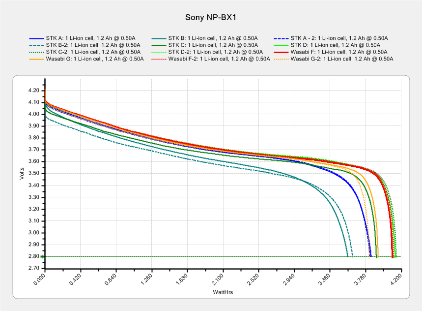
This sheaf of tests shows three of the four STK NP-BX1 batteries deliver about 4 W·h during a constant 500 mA discharge, with battery B trailing behind:
After the three most recent bike rides, I popped the partially discharged battery into the tester and used the same test current:
Sony NP-BX1 – STK ABD – charged vs used – Wh scale – 2015-11-22
The longer curves come from the top chart (with different colors), the shorter ones from the partially discharged batteries. In an ideal world, the shorter curves should give the energy left in the battery after the ride, so subtracting that from the before-ride capacity gives the energy used during the ride.
The results for battery A may not be typical, as the camera turned off before I rolled into the garage. The camera may run with a battery voltage below the 2.8 V cutoff in those tests, so it can extract more energy than the tests. The slope of the curve toward the end suggests it won’t get much, but that will still bias the results.
In round numbers, the bike rides required:
A: 3.8 – 0.1 = 3.7 W·h
B: 3.6 – 1.4 = 2.2 W·h
D: 4.2 – 1.0 = 3.2 W·h
I generally turn the camera off during the mid-ride pause (Protip: never wear a helmet camera into a Port-a-Loo), so at least two of the rides have discontinuous usage. I figured the total run time from the video file sizes at the rate of 22.75 min/4.0 GB, blithely ignoring issues like the battery recovering during the pauses, the effect of ambient temperature vs. camera heating on battery temperature, and so forth and so on.
In an ideal world, dividing the total energy by the run time (converted from minutes to hours and not venturing into pirate·ninja territory) should produce a nearly constant value equal to the camera’s power dissipation:
A: 3.7 W·h / 1.25 h = 2.96 W
B: 2.2 W·h / 1.0 h = 2.1 W
D: 3.2 W·h / 1.4 h = 2.25
Ignoring the suspiciously high result for battery A, it looks like the HDR-AS30V really does dissipate a bit over 2 W while recording 1920×1080@60fps video. That’s with GPS, WiFi, and NFC turned off, of course.
Which turns out to be pretty close to the test conditions: 3.7 V x 500 mA = 1.85 W. I could goose the test current to 600 mA = 2.2 W/3.7 V for the next tests, but maybe long-term consistency is a virtue.
Orienting the strips in alternate directions kept the white data connections between adjacent strips on the top and bottom level. If they sat in the same direction, the data wires would run from top to bottom.
Each Neopixel draw 60 mA max, so each side of the pillar can draw 180 mA and lighting up all four sides in full-throttle white draws a bit over 720 mA. That’s more than those little Wire-Wrap wires should be forced to carry, but the tiny Neopixel solder pads aren’t good for much more than that. The revised column model has wiring channels behind both strip ends to provide access to the slightly larger pads on the rear surface; the fact that all the end pads get cut in half doesn’t help matters.
The red and blue power wires connect adjacent strips, with two opposite strips wired in parallel at the bottom of the column. There’s a 100 µF cap across the incoming power leads: as much capacitor as would fit in the somewhat undersized base.
A knockoff Arduino Pro Mini sits inline between a 5.2 VDC wall wart and the Mood Light with three connections: VCC, GND, and D6. It’s flapping around in mid-air with no protection whatsoever, so I’ll let your imagination draw that picture. I want to hide it in the base, along with a power jack, as part of the fine tuning.
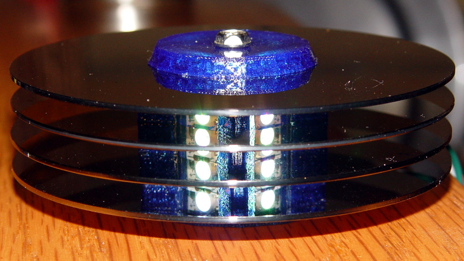
Anyhow, restacking the platters produced this pleasant effect:
Hard Drive Mood Light – low angle
You’re seeing each LEDs both directly and through a reflection in the platter below it. Despite having handled the platters for a few days, the reflection’s clarity surprised me; the multiple reflections required to bounce the LED image to the edge of the platter work perfectly:
Hard Drive Mood Light – high angle
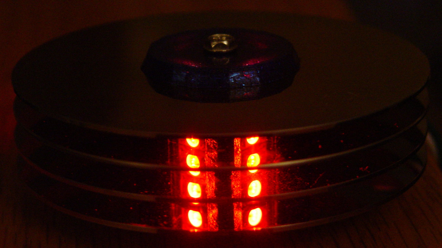
Running the original firmware (which, as noted in the comments, will eventually fall off its rails), the colors change slowly enough to be always the same while you’re watching and always different after you look away:
Hard Drive Mood Light – red
The platters stack sufficiently parallel to each other that the LED images still have the right spacing after multiple reflections. It’s not quite an infinite house of mirrors.
With the LEDs running at half intensity (PWM limited to 128/255), the stack lights up a dark living room just fine. At full throttle, it’d probably be too bright…
Adafruit’s Neopixels are RGB LEDs with a built-in current-limiting 400 Hz PWM controller and a serial data link. Successive Neopixels aren’t synchronized, so their PWM cycles can produce serious current spikes.
Lighting up just the red LED in two Neopixels at PWM 16/255 produces this current waveform (at 10 mA/div):
Neopixel current 10 mA – 16-0-0 0-1
Each red LED draws about 20 mA, so when the two Neopixel PWM cycles coincide, you get a nasty 40 mA spike. When they don’t coincide, you get a pair of 20 mA pulses. Those pulses walk with respect to each other at a pretty good clip; the oscillators aren’t trimmed to precision.
Lighting up three Neopixels with PWM 16/255 on the red does exactly what you’d expect. The horizontal scale is now 100 µs/div, making the PWM pulses five times wider:
Neopixel current 10 mA – 16-0-0 0-1-2
The narrow spike comes from the brief shining instant when all three Neopixels were on at the same time. Now you have three PWM pulses, each with slightly different periods.
Remember that these are PWM 16/255 pulses. When they’re at full brightness, PWM 255/255, there’s only a brief downtime between pulses that last nearly 2.5 ms and they’ll overlap like crazy.
Obviously, the more Neopixels and the lower the average PWM setting, the more the average current will tend toward the, uh, average. However, it will have brutal spikes, so the correct way to size the power supply is to multiply the number of Neopixels in the string by the maximum possible 60 mA/Neopixel… which gets really big, really fast.
A 1 meter strip of 144 knockoff Neopixels from the usual eBay supplier will draw 144 x 60 mA = 8.6 A when all the pulses coincide. Worse, the supply must be able to cope with full-scale transients and all the fractions in between. A husky filter cap would be your friend, but you need one with a low ESR and very high capacity to support the transients.
No wonder people have trouble with their Neopixel strings; you really shouldn’t (try to) run more than one or two directly from an Arduino’s on-board regulator…