Ed Nisley's Blog: Shop notes, electronics, firmware, machinery, 3D printing, laser cuttery, and curiosities. Contents: 100% human thinking, 0% AI slop.
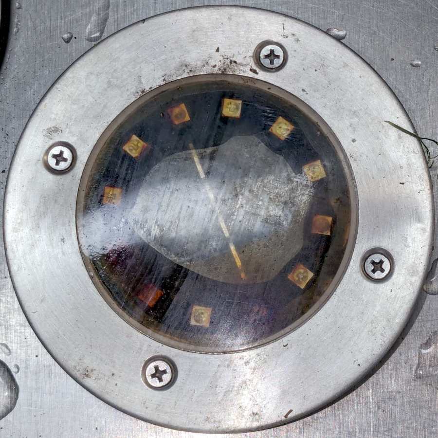
A solar yard / walkway light appeared in the far back reaches of the yard while mowing:
Solar yard light – bubble
Yes, that’s an air bubble in the middle, so you know the light hasn’t been staying in its Happy Place™.
As the djinn in the bottle put it, “Pop the top and let’s get started”:
Solar yard light – cover off
Those light emitting diodes around the photovoltaic cell in the middle can’t light up any more.
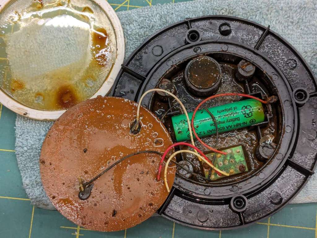
A little more effort with the Designated Prydriver reveals the guts:
Solar yard light – components
That’s an NiMH cell, so the light has been abandoned out there for quite a few years.
The photovoltaic element still worked, but the LEDs were defunct. The corpse will be a guest of honor at the next electronics recycling event down the road from here.
Someday, our great-to-the-nth grandchildren will curse our ways …
By a quirk of fate, the Chamberlain garage door opener in our new house has the same “purple learn button” as the Sears opener in our old house, so I introduced it to our remotes and they work just fine.
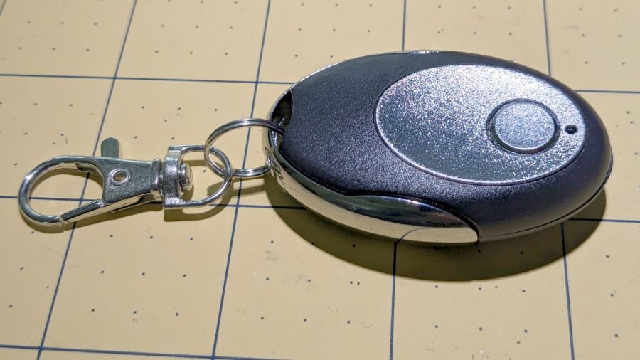
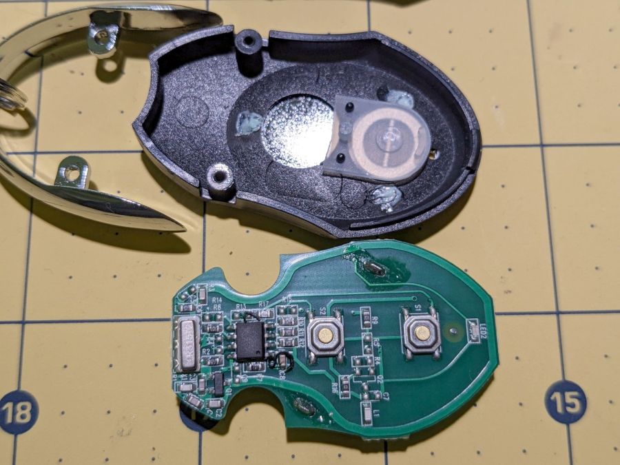
I then replaced the four-button remote in my bike pack with a new single-button remote to reduce the dexterity required to hit the button:
Garage Opener – one button
Alas, the opener only responded when the remote was immediately outside the aluminum garage door. Checking the battery (because sometimes “new” does not mean what you think it means) reminded me we live in an age when hardware is free compared with bookkeeping:
Garage Opener – interior
Maybe the second button doesn’t work and this is how they monetize their QC reject pile?
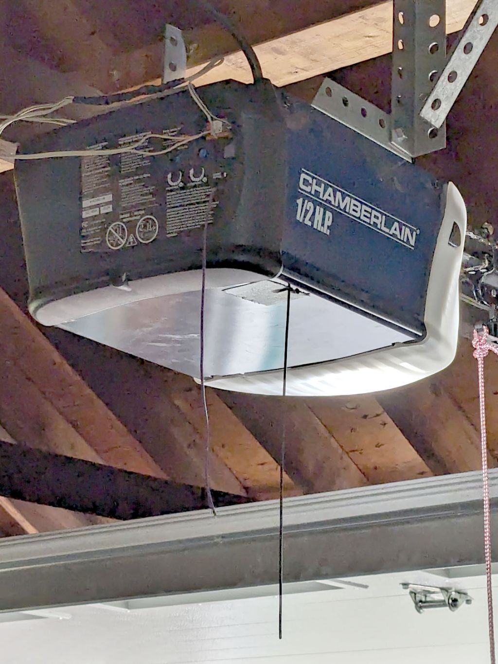
I want the door to start moving when I’m at the end of the driveway, giving it enough time to get all the way up so I can bike right in. You can actually buy remote / extension antennas, although for fancier openers with SMA antenna connectors, but sometimes a little RF black magic will suffice:
Garage Opener – crude antenna director
The wavy wire hanging down from the opener’s rear panel is the original antenna, which might be kinda-sorta omnidirectional. The opener operates around 433 MHz= 69 cm, so a quarter-wave antenna will be 17 cm = 7 inch long; the (unbent) wire is maybe 10 inches long from the hole in the panel.
So I taped 11 inches of wire to the opener to form a very very crude Yagi-Uda antenna. It’s too long to be a director element, it’s about right (albeit in the wrong place) to be a reflector element, it might be neither.
What it does do is warp the antenna’s pattern just enough to let the remote reliably trigger the opener as I approach the end of the driveway.
Do not even begin to think about polarization mismatch from what looks like the tiny loop antenna on the remote’s PCB.
As a temporary expedient while awaiting more outlets in the basement, I screwed several hundred watts of LED strip lighting to the floor joists so I could see where I was going:
First pass at basement lighting
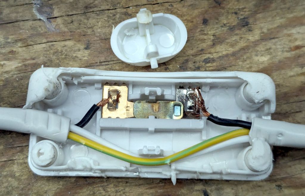
The switch seemed to run warm, which I attributed to being snuggled up against one of the LED strips, eventually became intermittent, and finally failed with the lights out.
Prying apart the snapped-together case destroyed it, but that didn’t really matter when I saw the innards:
T8 LED power switch
The “intermittent” action came from the melted post on the switch actuator at the top of the photo. The “warm” came from the barely crimped black wire on the right side of the switch, which *might* have had half a dozen strands caught in the flattened crimp triangles.
I replaced it with an identical switch from the assortment that came with the lamps. That one seems to run cooler, although I doubt the crimps are really up to any reasonable quality standards.
In addition to adding basement outlets & lighting circuits, the rest of the house has some electrical wiring peculiarities; the kitchen microwave really shouldn’t share a circuit with the dining room lights.
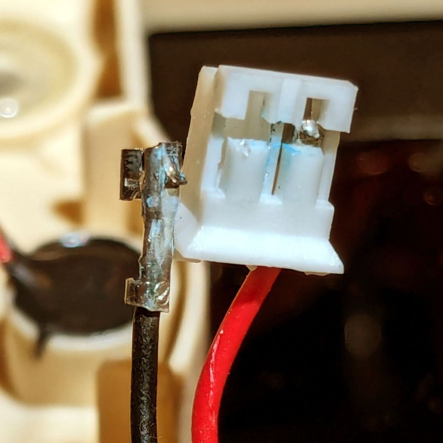
Having had several folks ding our front doorbell in recent weeks, I thought it would be nice if the switch had a light inside and was mildly surprised it didn’t. Taking it apart revealed an even bigger surprise:
Doorbell – circuitry
Much electronic! Many solder!
Obviously, that’s a bridge rectifier (MB6S for the curious) in the middle, with a pair of paralleled 1 kΩ SMD resistors on either side ballasting two white LEDs in series on the other side. As far as I could tell, both LEDs had stopped being diodes, most likely after one failed short and took the other down with it.
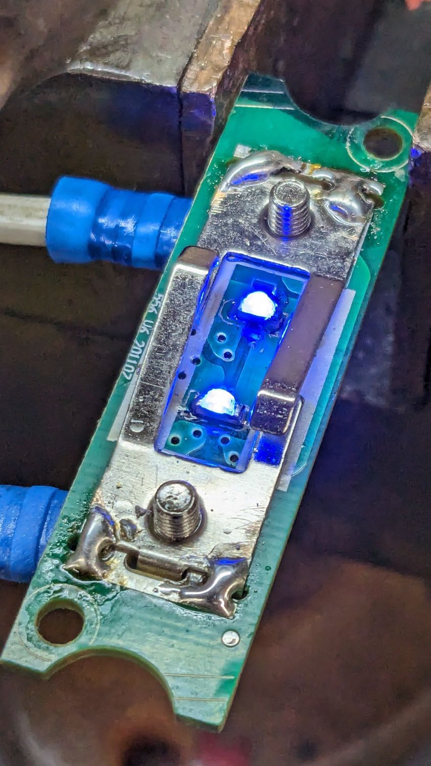
Having recently unpacked the small parts cabinet containing SMD LEDs, I could do this:
Doorbell – blue LEDs
While I had the iron hot, I resoldered the fractured blobs attaching the spring contacts to their solder pads. I think the 201107 along the left edge is the PCB date code, so the switch has been in place for maybe a decade.
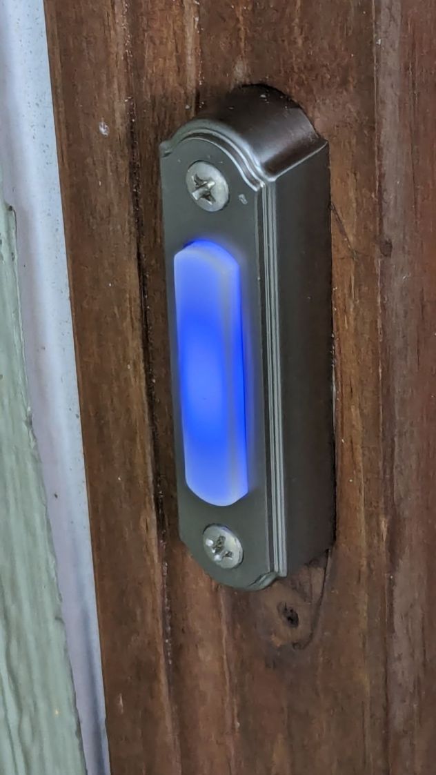
You gotta admit blue is distinctive:
Doorbell – installed
While taking it off, I discovered it’s the second doorbell button in that spot; you can’t see the bottom screw hole and wood scar when you’re standing at the door. Unless, I suppose, you’re three feet tall, but most folks of that stature aren’t curious about doorbells.
Update: An alert reader provided more information:
I recently bought a doorbell button, Heath Zenith SL-315-1-90. […] My board is different but has the same circuit as yours. In case it’s helpful, I believe your button might be Heath Zenith SL-257-02.
That’s a perfect example of a “brand name” completely detached from its entire history and put to work doing something entirely different. AFAICT, I honored the Heath name by resoldering the poor thing.
Alas, the doorbell switch on the back door turned out to be a dead loss. Perhaps when they replaced the door, the wire got sliced just above the sill plate, leaving a stub in the basement and no way to fish a new wire to the switch. Anybody arriving via the trail from the Vassar College property out back must bang on the door to get our attention.
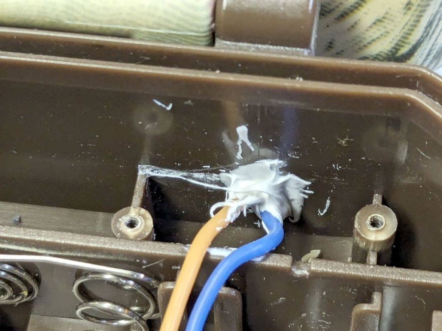
I thought cleaning that mess up would solve an intermittent power problem, but the camera continued to fail immediately after being deployed and finally refused to work at all.
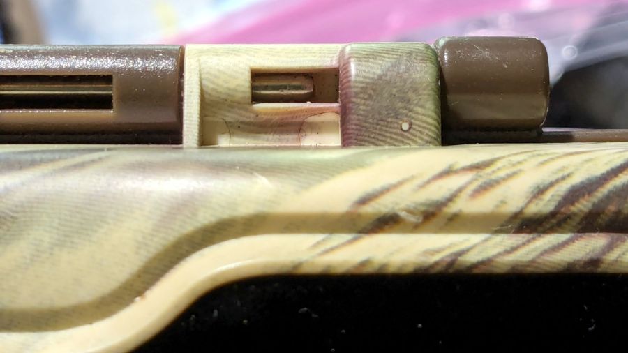
The camera case has eight (!) AA cells in one half connected to the electronics in the other half by a pair of wires that pass through the hinge between the halves:
M50 Trail Cam – pivot wire route
The steel rod is the hinge pivot, with the battery half wearing brown and the electronics half in lighter plastic. As you’ll see in a bit, the rod is fixed in the electronics half and the battery half pivots around it.
The two short case sections on the right contain the two wires carrying the 6 V battery power. Some gentle manipulation suggested the fault lay inside those hinge sections, which meant I had to figure out how to get them apart.
The other end of the steel rod has a knurled section jammed firmly into the electronics half, but I managed to carve away just enough plastic to expose just enough of the knurl to get just enough of a grip (yes, with a pair of genuine Vise-Grip 10WR Locking Pliers, accept no substitutes) to yoink the rod out:
M50 Trail Cam – extracted pivot
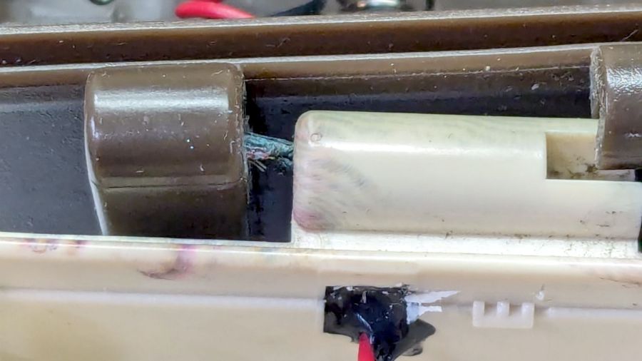
With the hinge released, the problem became immediately obvious:
M50 Trail Cam – failed hinge wires
Yes, those are wire strands poking out of the hole in the left hinge section.
A tedious needle-nose tweezer session extracted the remains of the wires from the hinge and cleaned out the adhesive:
M50 Trail Cam – extracted OEM PVC wires
Although those two hinge sections are hollow with plenty of room for the wire, it seems the assembler squirted adhesive into both sections to glue the wires in place. As a result, every time I opened the case to charge the batteries, maybe two millimeters of wire twisted 180° degrees. The wonder is that it lasted as long as it did.
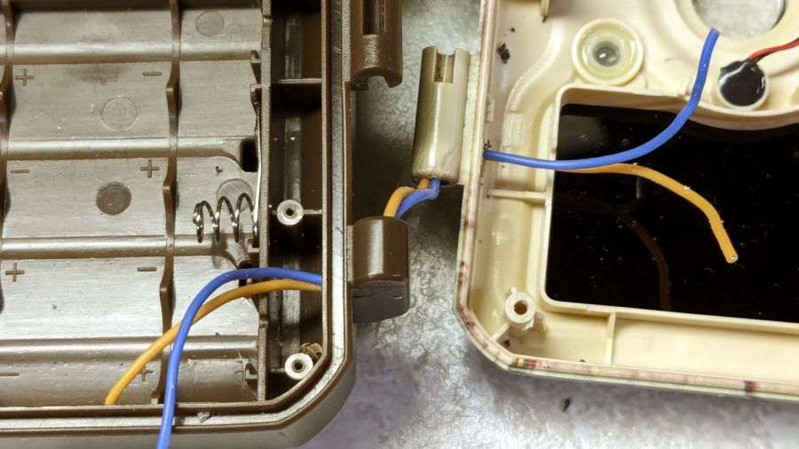
I snaked a pair of 20 AWG silicone-insulated wires through the hinge sections:
M50 Trail Cam – silicone rewiring
The OEM wires had PVC insulation, which is a terrible choice for wires that will undergo lots of flexing, but that’s what SJCam used.
Two untidy blobs of acrylic caulk do at least as good a job of sealing the case openings as the black gunk visible in the earlier pictures:
M50 Trail Cam – new caulk
I left all of the wire in the hinge un-stuck, hoping the twist will distribute itself over maybe 5 mm of wire and last longer.
In anticipation of future repairs, however, I left enough of the knurled end of the hinge rod exposed to get an easy grip:
M50 Trail Cam – restaked pivot
Solder the new wires to the old pads, assemble in reverse order, and it works as well as it ever did:
The alert reader will note I did not reset the camera clock after charging the batteries, a process requiring the janky SJCam app.
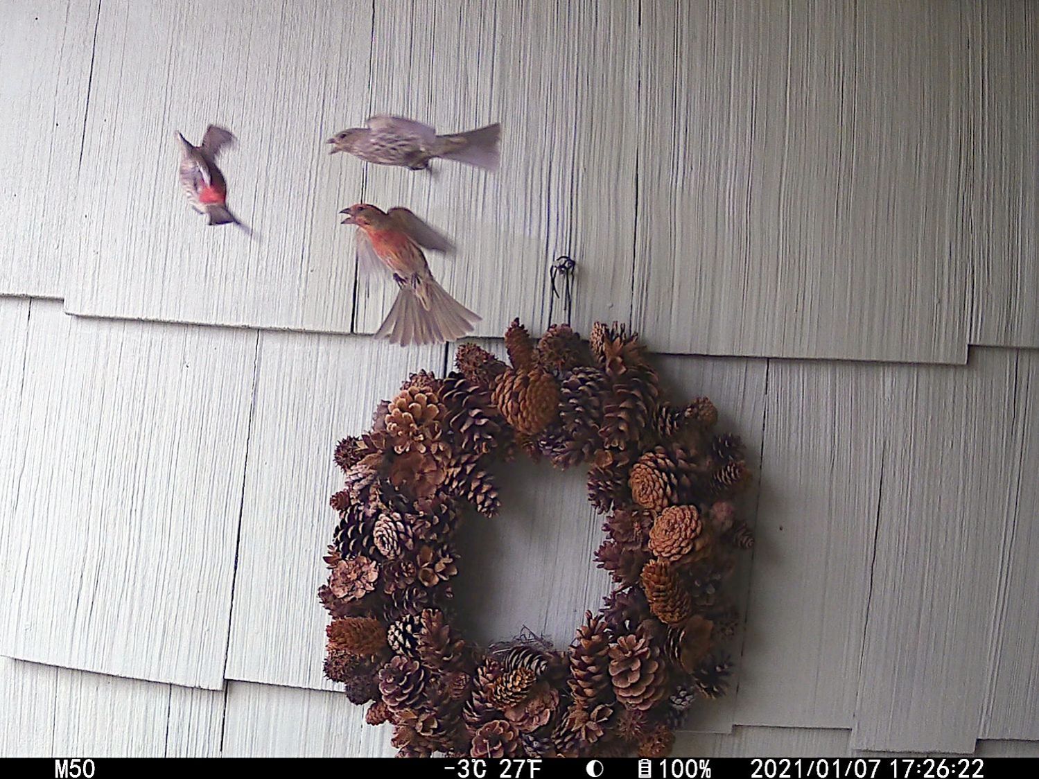
The two finches on the right have been constructing a nest in the wreath hanging at our front door. They tolerate our presence, although they’d be happier if delivery folks dropped packages elsewhere.
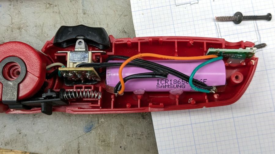
In anticipation of upcoming disassembly & reassembly tasks, I finally replaced the long-dead NiCd battery in an old Skil cordless driver with an 18650 lithium cell from the Basement Warehouse Wing:
Skil Cordless Driver – 18650 cell overview
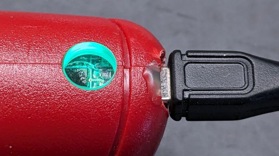
A USB charge controller sits in a slot carved into the plastic formerly supporting the NiCd battery’s charging jack:
Skil Cordless Driver – USB charger detail
Hot-melt glue holds everything in place.
The motor draws about 2 A under full load, which is a bit more than the charge controller wants to supply. I simply wired the motor (through its reversing switch) directly to the 18650 cell terminals, which is certainly not good practice, but seems reasonable given the intended use case.
A red LED shows the charger stuffing energy into the cell:
After an hour, a green glow shows the cell is fully charged:
Skil Cordless Driver – full charge
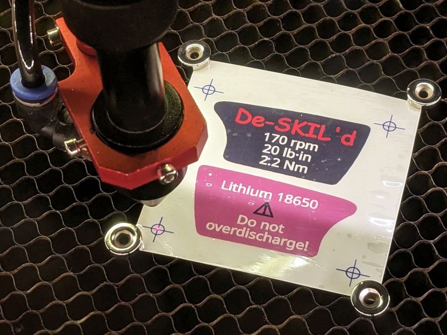
The original label proudly touted the NiCd battery’s 2.4 V, so I figured truth in packaging required a new label:
Skil Cordless Driver – new label cutting
The process:
Scan the original labels
Blow out the contrast to make binary masks
Trace into vectors with LightBurn, simplify & clean up
Add targets for Print-and-Cut
Save as SVG, import into GIMP, lay out text, print
Cut the outlines
The labels have laminating film on the top and craft adhesive on the bottom, both of which cut neatly and look pretty good:
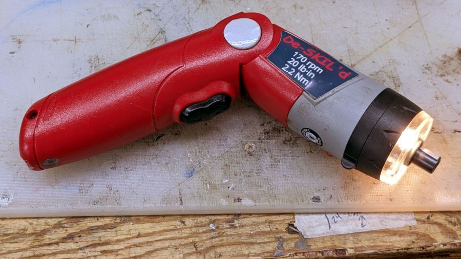
Skil Cordless Driver – lithium in action
The alert reader will note the 4+ V from a fully charged lithium cell exceeds the 2.4+ V from fully charged NiCd cells, which accounts for the very bright incandescent headlamps. I figure 4 is roughly equal to 2.4, for large values of 2.4: the driver ticks along at 170 RPM instead 140 RPM.
I measured the torque using a double-ended hex bit in a torque screwdriver, with the torque setting cranked up until the driver just barely clicked it over.
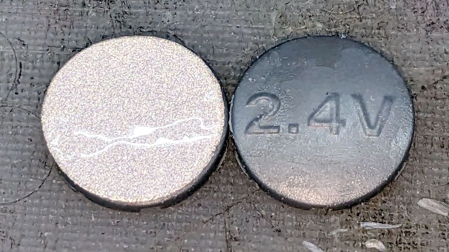
I took the liberty of filing the raised “2.4 V” off the hinge covers and adding tidy retroreflective disks:
Skil Cordless Driver – hinge cover
I briefly considered adding “3.7 V” (because “4.2 V MAX” wouldn’t fit) in laser-cut PSA vinyl, but it was getting late.
The sellers have accepted our offer on their house, so over the course of the next couple of months we’ll be moving, then selling this place. Having begun dismantling and packing the contents of the Basement Shop, Laboratory, and Warehouse, my blog-worthy activities will grind to a temporary halt.
Should you or anyone you know be interested in moving to the trendy Hudson Valley region, we have a conveniently located property with a shop-ready basement: