Ed Nisley's Blog: Shop notes, electronics, firmware, machinery, 3D printing, laser cuttery, and curiosities. Contents: 100% human thinking, 0% AI slop.
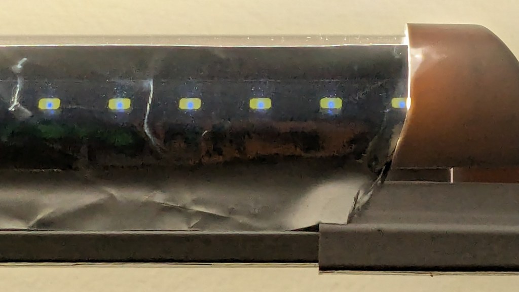
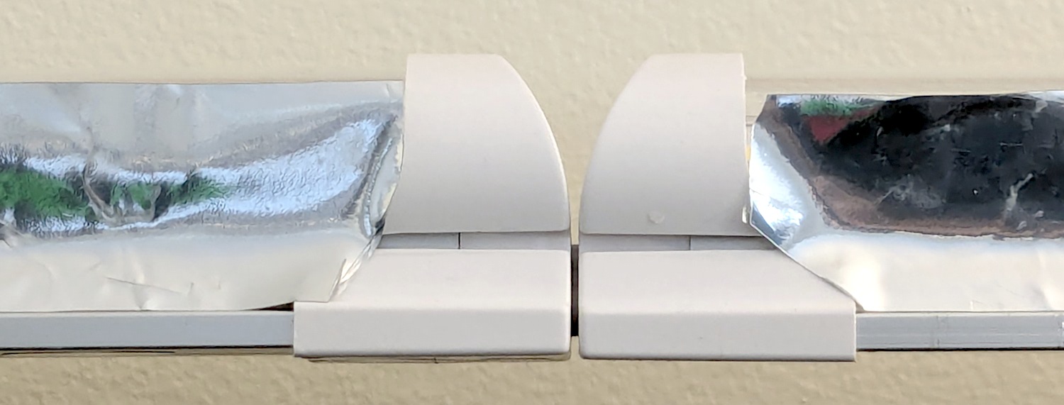
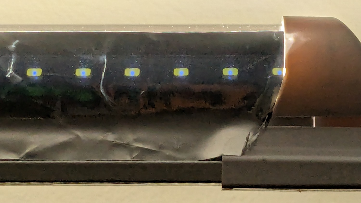
This is a quick-and-ugly test to see how well aluminized Mylar will work as a reflective shade for some LED light bars eventually washing the Living / Sewing room ceiling with enough light to brighten the Sewing Table:
LED strip light – Mylar reflector – ugly fit
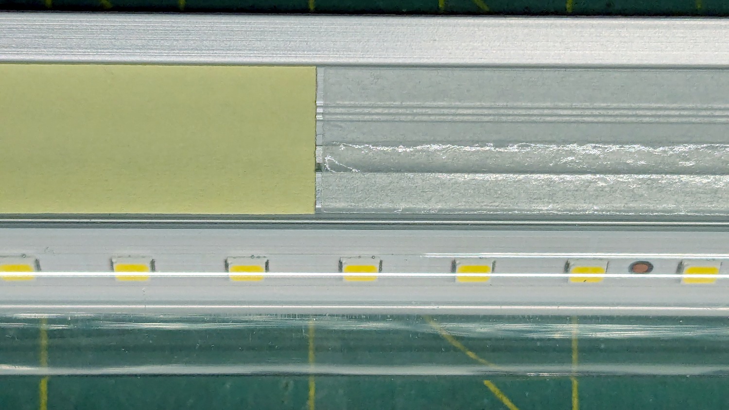
The key question: how well adhesive adheres Mylar to the pleasantly warm aluminum extrusion serving as the heatsink for 40 W of LEDs:
LED strip light – Mylar reflector – adhesive strips
Perhaps surprisingly, those ½ inch strips come from an A4 sheet by way of a paper cutter.
The LED bars will be directly visible, so bouncing the direct light against the wall reduces glare and puts it to good use.
The Mylar strips are 1 inch wide, cut with a utility knife against a straightedge, although ⅞ inch seems adequate. The last LED over on the right sits at the endcap, so I will (try to) tuck the Mylar ends under the caps for a cleaner fit.
The bars have two 4 foot strips of LEDs in series, with a lump of circuitry buried in the aluminum extrusion that seems be a bridge rectifier and a small electrolytic capacitor. There’s not nearly enough capacitance to knock down the 120 Hz flicker and I have an uneasy expectation of stroboscopic effects on the sewing machines.
Installing the new ball-mount laser stylus on the HQ Sixteen’s electronics pod required nothing more than two strips of good foam tape:
HQ Sixteen – Stylus Laser – installed – overview
In actual use, you would:
Lay down a “pantograph” pattern on a paper strip along the rear track under the machine’s carriage
Position the needle at the appropriate spot on the quilt
Aim the laser at the corresponding point on the pattern
Start the machine!
Move the laser spot along the pattern while the machine stitches that pattern in the quilt
Mary thinks free-motion quilting is easier and I’m not in a position to argue the point.
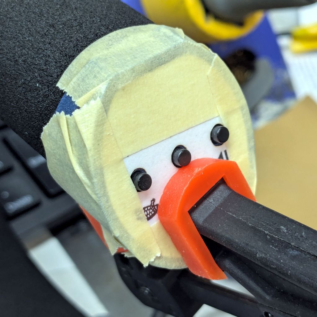
Anyhow, the key feature of my ball mount is that it’s completely out of the way:
HQ Sixteen – Stylus Laser – installed – front
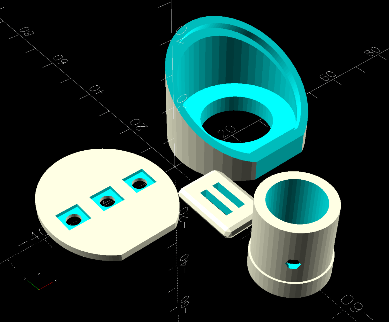
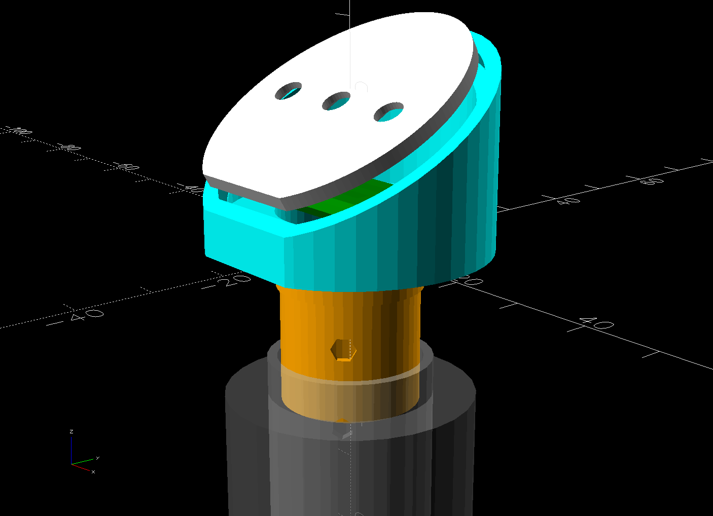
Which looks comfortingly like the original solid model:
HQ Sixteen – Stylus Laser Mount – solid model – show
Minus the vivid red death ray and pew! pew! pew!
Power comes from a barrel jack in the back intended for the original stylus laser; all small lasers, unless otherwise noted, run from 5 VDC. The jack is 3.5×1.3 mm, but the Drawer o’ Weird Barrel Plugs disgorged a matching right-angle plug. Unsurprisingly, such things are readily available these days.
Splice the laser leads to the plug and cover the evidence with a braided loom + heatshrink tubing:
HQ Sixteen – Stylus Laser – installed – rear
I considered a switch, but the anticipated low duty cycle suggested just unplugging it, so that’s that.
Quite by coincidence, a few days earlier a friend reported the speaker in her Ooma Telo2 had failed. This seems to be a common failure mode, with the rest of the gadget continuing to work fine.
The failed speaker showed continuity through its coil and, in fact, still had the same 8 Ω DC resistance as an identical speaker pulled from the Drawer o’ Small Speakers. It did not, however, make a sound when connected to a signal generator, where the new speaker squeaked happily.
So it seems the speaker failed by a mechanical jam, rather than an electrical / wiring failure. It’s not as though we play thrash metal music through the thing, but apparently the magnet disintegrated:
Samsung speaker magnet disintegration
Yes, the coil gap is full of nicely oriented magnetic particles:
Samsung speaker magnet disintegration – detail
If Samsung (or whoever built the speaker) used a poorly sealed neodymium magnet, then it would crumble exactly as shown.
I wonder if that’s how the original speaker failed.
Installing the identical replacement speaker involved more hot melt glue and, as expected, restored the Telo2 to normal operation:
The ↓ (“down”) button on one of our lift chairs stopped working, although the ↑ (“up”) button worked fine and, as you’d expect, verifying this problem left the chair in a rather awkward position.
The usual power cycle and unplugging / replugging the control had no effect.
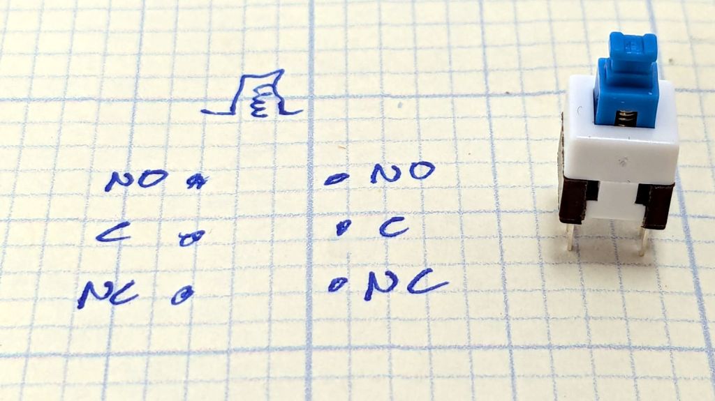
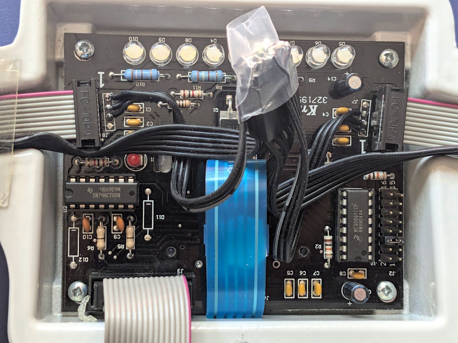
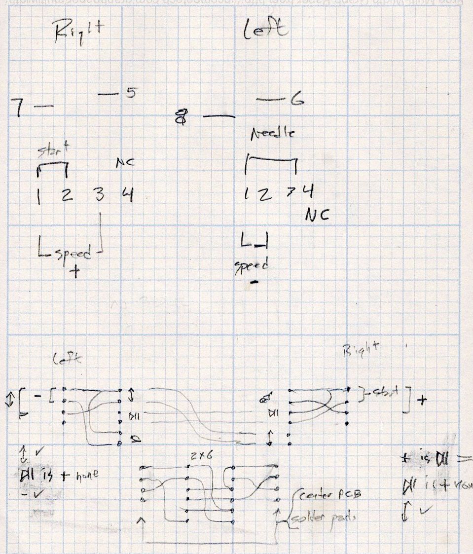
This control is the one I couldn’t pry apart to dim its LEDs, so I tried various combinations of pins until this scribble emerged:
Pride Lift Chair – control pinout doodle
I have no idea of the correct pin numbering, but the scribble looks into the connector pins with the keyway on top:
Pride lift chair control
The more intricate control for the other Pride lift chair has only four pins in its connector, so I couldn’t just swap them to see what happened.
The polarities are for the continuity / resistance test probes.
The takeaway: The two buttons did similar things to two different connector pins, so the control seemed to be working correctly and the fault lies elsewhere.
The control sports a USB jack for powering / charging your favorite device and I’m reasonably sure the control has a microcontroller tucked in there for good reason, implying the circuitry is surely more complex than maybe a rectifier bridge and some resistors.
So I shoved the chair into the middle of the room, deployed some test equipment, reconnected the control, plugged the chair power supply into the outlet strip, and … of course both buttons worked perfectly.
Soooo the chair is back in place and we’ll see what happens next.
Speaking of Heisenbugs, the HQ Sixteen continues to work fine, too.
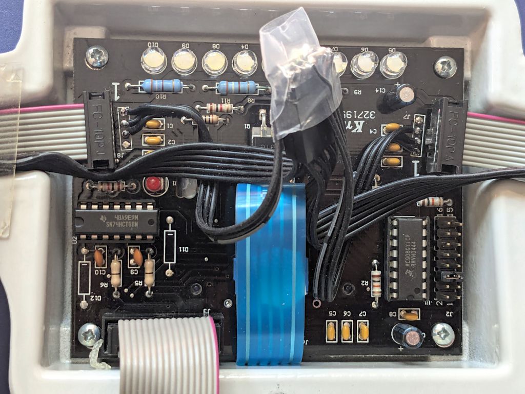
After running reliably for a few weeks, the HQ Sixteen Heisenbug returned, displaying a Motor Stall error on the first attempt to run the motor. This gave me the opportunity to extract the PCB, compare it with the first rough schematic, then correct a few resistor values and connections.
Do not assume any connections or components are correct or correctly drawn.
!!CAUTION!! The motor supply is direct-from-the-AC-line non-isolated +160 VDC.
!!CAUTION!! The GND traces are not isolated from the AC line and are not at the normal “0 V” AC neutral potential.
When the machine operates normally, the relay pulls in with a distinct click slightly after the power switch closed. With the Heisenbug in full effect, the relay does not click, suggesting a fault in its driver circuitry.
With the motor pod resting on a box beside the machine, I gingerly measured the voltage at various points on the top of the PCB. As far as I could tell, the entire +15 VDC power supply was dead: no voltage at either the input or output terminal of the LM7815 regulator!
NOTE: The obvious screws along the top edge of the PCB are not connected to the power PCB circuit GND. Instead, they’re part of the controller’s power circuitry from the isolated power supply produced by rectifier bridge B3 and passed through J1 in the upper left corner of the PCB. Instead, the left lead on R1 (the 5W sandbox resistor) is a convenient GND terminal.
So I hauled the little DSO150 battery-powered oscilloscope and a handful of clip leads up from the Basement Laboratory, got everything arranged, turned on the power, and the machine worked perfectly again.
That’s why it’s called a Heisenbug: look at it and it vanishes.
Given a faint indication of power supply problems, I verified all four diodes in Bridge Rectifier B21 are OK and the Skynet transformer windings were solid. I resoldered all the PCB connections from the transformer to U2, the LM7815 regulator, plus the green jumper wires.
The machine is now back together, it continues to work, and all my test equipment is back in the basement.
If it happens again, I’ll mount a cheerful LED on the pod to show the supply is working.
With the manual laser pulse button in place, I measured the beam power at the entry and exit planes of Mirror 1 and Mirror 2, with the differences indicating something about the reflectivity (or lack thereof) of the molybdenum mirrors. Given that the losses are on the order of a few percent, tops, I expected this to be below the repeatability of the measurements.
The Mirror 1 entry point is basically the same as the laser tube exit:
HLP-200B – Laser tube exit
The Mirror 1 exit plane is perpendicular to that, just behind the mirror, but there is no way I can get a picture of the arrangement. Suffice it to say I do not want to ever put any body parts that close to an operating laser tube again.
The HLP-200B meter turned out to be exactly the right length to stand on its own in front of Mirror 2, although I needed a few test shots to figure out the lateral positioning:
HLP-200B Mirror 2 entry check
The Mirror 2 exit measurements were hand-held, with the meter braced against the mirror mount brackets on the gantry:
HLP-200B Mirror 2 exit
Without further ado, the results:
M1 Entry
M1 Exit
M2 Entry
M2 Exit
35.5
31.2
30.3
32.9
28.3
30.6
29.1
32.6
31.8
22.8
27.8
28.9
30.3
29.0
29.4
28.5
26.9
28.4
28.7
27.0
31.1
31.7
28.6
26.9
30.7
29.0
29.0
29.5
2.99
3.27
0.84
2.67
The bold line gives the average of the six measurements at each position, with the sample standard deviation below that.
As expected, the pulse-to-pulse variations swamp any actual differences between the entry and exit power levels; Mirror 2 does not have a net power gain. A 2% loss in the mirror is 0.6 W at 30 W, obviously far too small for the HLP-200B meter to resolve.
The light is unavoidably upside-down from the industrial standard, because I can’t don’t want to mount it on the laser cabinet, and my use of color does not match the industrial convention. Neither of which matter for my simple needs.
The blue and orange lights turn on when their inputs are active, so they positively show sensor satisfaction, rather than laser-disabling dissatisfaction. The entire stack lights up while the controller runs a job with assist air turned on, which is usually the case.
(See below for a slipstream update.)
The wiring diagram on the case is the only documentation enclosed with the stack light:
Stack Light – label diagram
Any power supply between 12 VDC and 24 VDC will work and, contrary to the label, the COM lead can be either polarity: the light works in either common-anode or common-cathode configuration. Because the laser controller inputs and outputs are all low-active, I wired the COM terminal to +24 V, so pulling the other leads to GND turns on their lights.
The overall connection diagram, in order from easy to hard:
Stack Light – wiring diagram
Some of the details behind the diagram explain what’s going on.
Stack Light – water protect wiring diagram
The water flow sensor is wired in series with the chiller, with a GND connection on the far end pulling the WP controller terminal low when both sensors are happy; the switches can handle another 50 mA of LED current with no problem.
Stack Light – L-ON wiring diagram
The HV power supply has an internal pullup to +5 V on its L terminal, which means the L-ON output terminal sits at +5 V when the laser tube is off. Connecting the stack light directly to the L-ON terminal dumps the LED current into the 5 V supply through the pullup resistor, producing a somewhat weak glow in the LED when it should be off.
Running the optoisolator input from 5 V solves that problem, as its diode will be off when the L-ON output is high. When it’s low, the diode turns on, the isolator’s output transistors conduct, and the stack light gets the full 24 V it expects.
Stack Light – lid sensor wiring diagram
The lid sensor normally goes only to the IntLock controller terminal, but I also ran it to the otherwise unused P terminal on the HV power supply, in the possibly misguided belief it would prevent the supply from firing with the lid up if it failed like the first one. Those two inputs have 5 V pullups, so the optoisolator handles the stack light’s 24 V supply.
Stack Light – status and assist air wiring diagram
When I added the dual-path air assist plumbing, diode D1 turned on the air pump when either the Statusor the AuxAir output turned on. When the job calls for assist air, the AuxAir output opens a valve to increase the air flow.
The Status output is active when the controller is running a job and that’s generally the only time the AuxAir output will be active, but the machine console has an Air button that manually activates it, so diode D2 isolates the Status output in that unusual situation.
Slipstream update: I realized swapping the green & orange lights would make more sense: