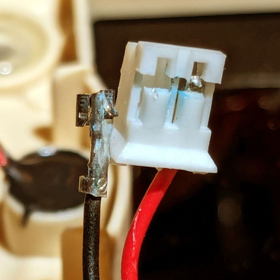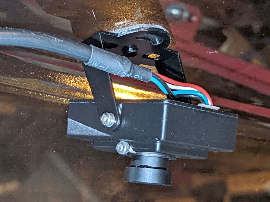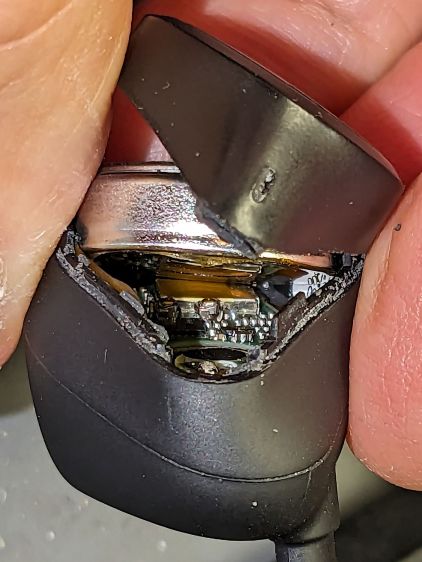
Having had several folks ding our front doorbell in recent weeks, I thought it would be nice if the switch had a light inside and was mildly surprised it didn’t. Taking it apart revealed an even bigger surprise:

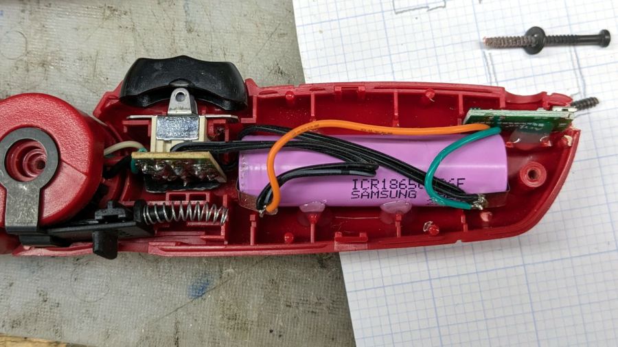
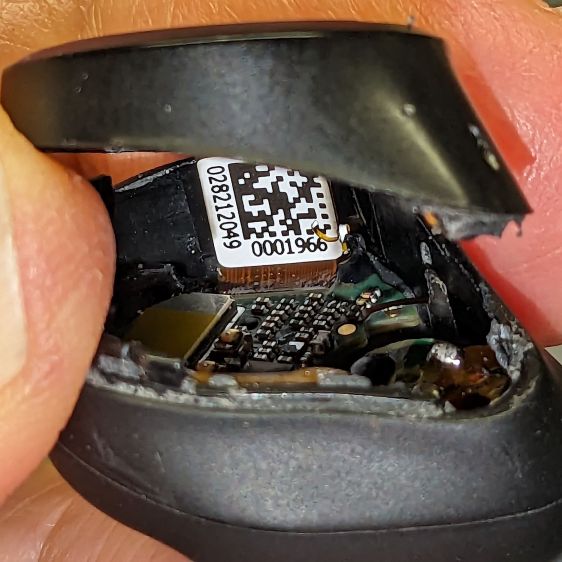
Much electronic! Many solder!
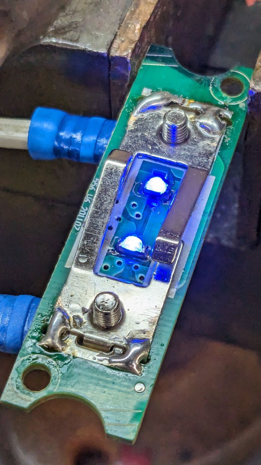
Obviously, that’s a bridge rectifier (MB6S for the curious) in the middle, with a pair of paralleled 1 kΩ SMD resistors on either side ballasting two white LEDs in series on the other side. As far as I could tell, both LEDs had stopped being diodes, most likely after one failed short and took the other down with it.
Having recently unpacked the small parts cabinet containing SMD LEDs, I could do this:

While I had the iron hot, I resoldered the fractured blobs attaching the spring contacts to their solder pads. I think the 201107 along the left edge is the PCB date code, so the switch has been in place for maybe a decade.
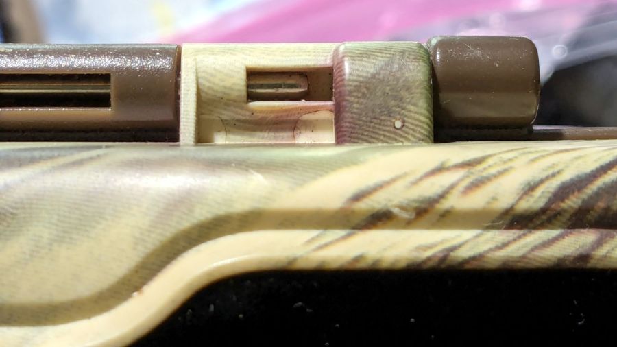
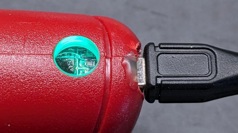
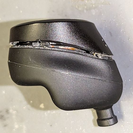
You gotta admit blue is distinctive:
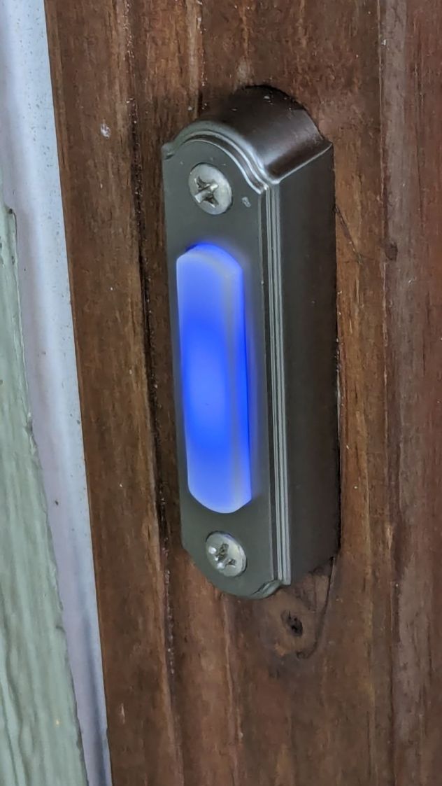
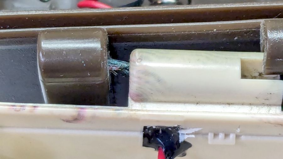
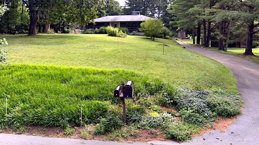
While taking it off, I discovered it’s the second doorbell button in that spot; you can’t see the bottom screw hole and wood scar when you’re standing at the door. Unless, I suppose, you’re three feet tall, but most folks of that stature aren’t curious about doorbells.
Update: An alert reader provided more information:
I recently bought a doorbell button, Heath Zenith SL-315-1-90. […] My board is different but has the same circuit as yours. In case it’s helpful, I believe your button might be Heath Zenith SL-257-02.
That’s a perfect example of a “brand name” completely detached from its entire history and put to work doing something entirely different. AFAICT, I honored the Heath name by resoldering the poor thing.
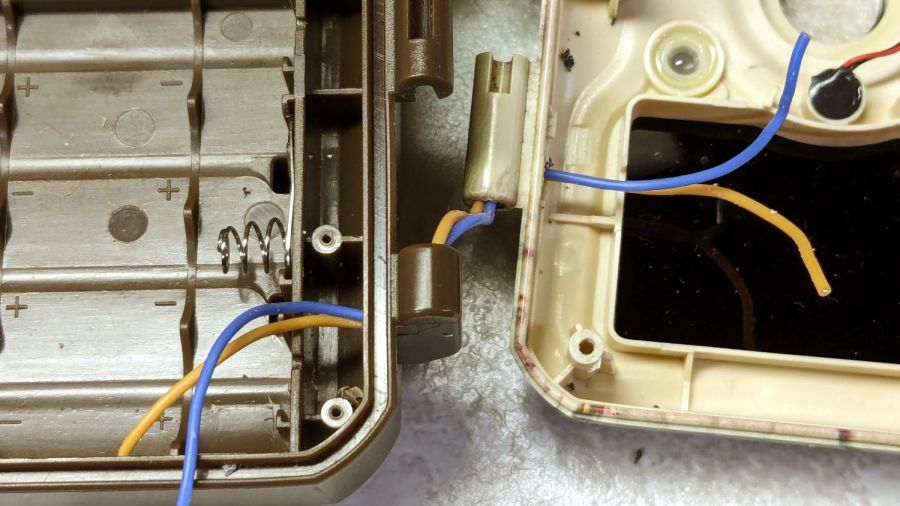
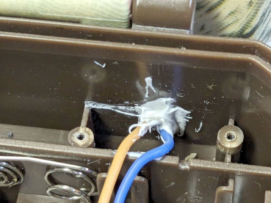
Alas, the doorbell switch on the back door turned out to be a dead loss. Perhaps when they replaced the door, the wire got sliced just above the sill plate, leaving a stub in the basement and no way to fish a new wire to the switch. Anybody arriving via the trail from the Vassar College property out back must bang on the door to get our attention.