Ed Nisley's Blog: Shop notes, electronics, firmware, machinery, 3D printing, laser cuttery, and curiosities. Contents: 100% human thinking, 0% AI slop.
Although essentially all kitchens feature a microwave over the stove, essentially all women have difficulty reaching it. As a result, our kitchen has two microwaves: the built-in Samsung over the stove and our trusty Sears Kenmore on the counter.
We’ve had it for a while:
Sears Microwave – data plate
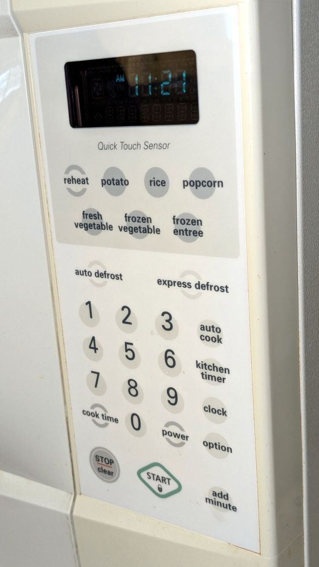
Apart from the turntable rollers, it’s been utterly reliable for the last two decades, until the Start button stopped working:
Sears Microwave – control panel
The membrane switch panel seems to be in good shape, with no cracks in the plastic surface. Only the Start button failed, which suggested the switch contact pad had failed and ruled out broken matrix traces on the flexible circuitry.
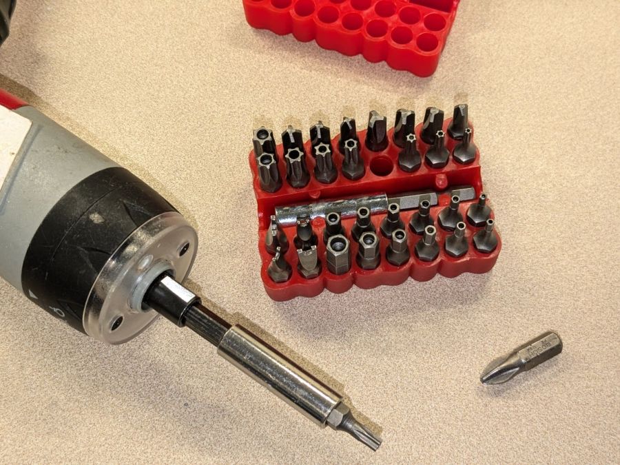
Back in the day, they kept casual tinkerers out of the dangerous interior:
Sears Microwave – Torx security screw
That would not be me:
Sears Microwave – security bit set
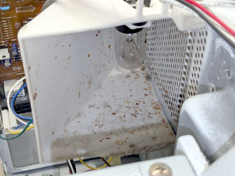
Over the course of two decades, an occasional food explosion produces a surprising amount of debris:
Sears Microwave – exhaust vent spatter
Go ahead, I dare you, show us your microwave exhaust vent.
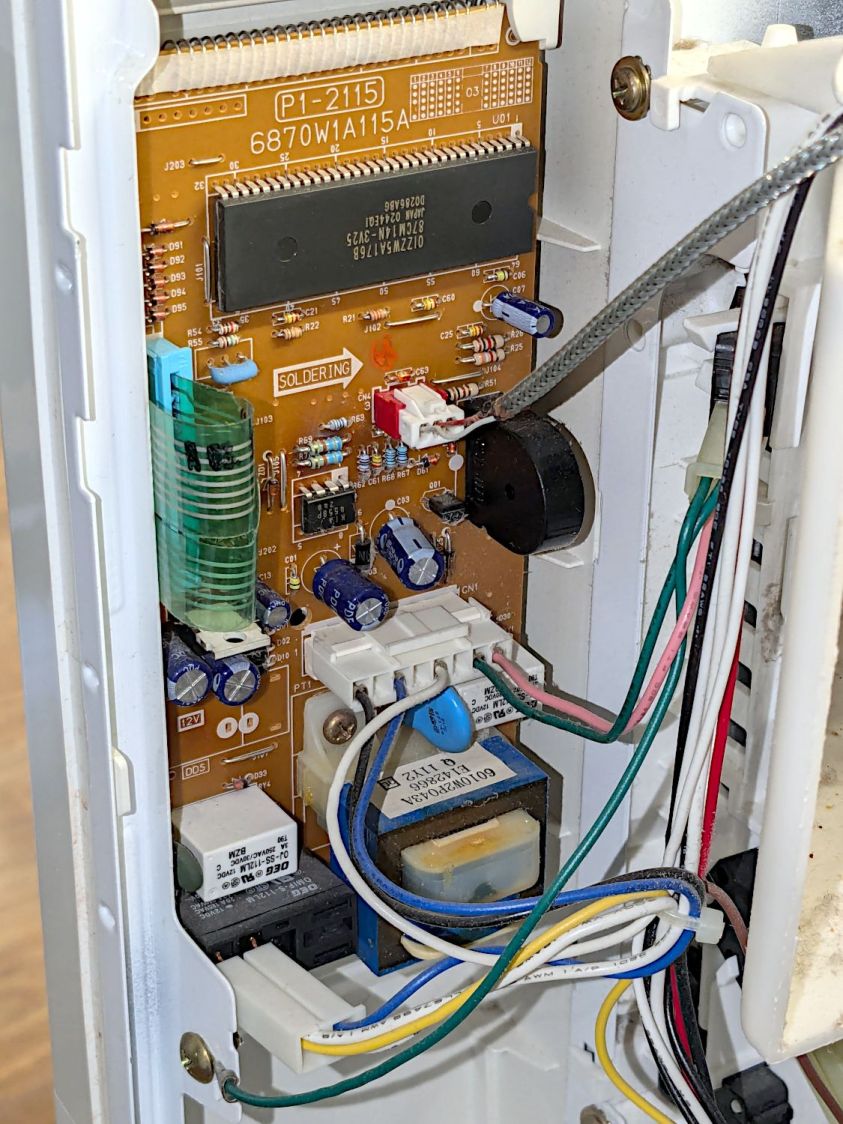
The control panel circuit board & wiring looks like this:
Sears Microwave – control board – in place
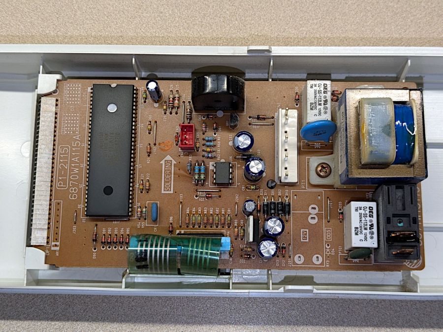
Unplugging all the connectors proceeds as you’d expect, whereupon a single screw (out of sight to the top) releases the control assembly and pulling the whole thing upward gets it out of the cabinet:
Sears Microwave – control board
The capacitors show no signs of The Plague, but those resistors near the optoisolator (?) in the middle have a suspicious thermal plume.
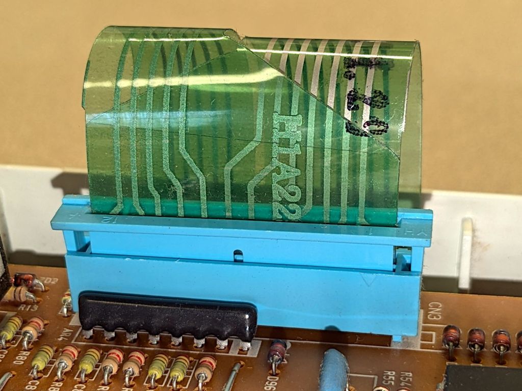
The ribbon cable from the control surface goes into a connector with the usual locking collar:
Sears Microwave – control panel cable connector
The cable also has cutouts latching into tabs molded into the collar:
Sears Microwave – control panel ribbon cable – locking tabs
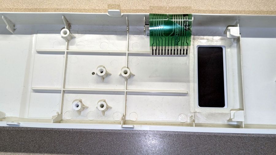
Removing two screws at the transformer releases the PCB:
Sears Microwave – control panel interior
Which promptly slammed the whole repair mission to a dead stop: with the entire membrane switch assembly glued to the front of the plastic shell, there is no way to get to the Start switch. Trying to peel the membrane off will most certainly destroy it.
Because all the other functions still worked, including the Add Minute button, we figured we can eke out a few more years before something else fails or the lack of one button gets intolerably annoying.
I reassembled everything in reverse order, plugged it in, and, while setting the clock, discovered the Start button once again worked perfectly.
It’s a classic laying-on of hands repair: take something apart, replace nothing, reassemble, and it works!
If the Start button is not part of the overall switch matrix, with a separate conductor through the ribbon cable, un- and re- plugging would be enough to restore a flaky contact. We’ll never know the rest of the story, although with this post as a reminder, maybe I can remember to tear the matrix apart when we scrap it out.
Although replacing the Sonicare E5000 battery six years ago was supposed to be the last time I’d do that, the poor thing died leaving most of a year’s supply of brush heads in the drawer.
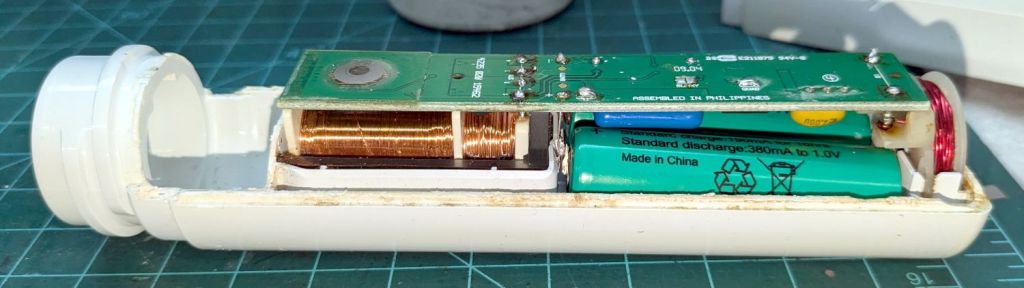
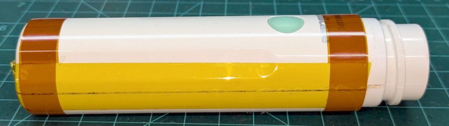
Half a quartet of NiMH AA cells should keep it happy while using up that stash:
Sonicare Toothbrush – NiMH AA cells installed
The AA cells sit at a jaunty angle due to re-re-using the original contact tabs soldered into the PCB.
I’m getting pretty good at taping the case closed:
Sonicare Toothbrush – Kapton tape
Although I have no pictures to prove it, the other half of the AA cell quartet restored youthful vigor to the Norelco T770 beard trimmer. Having interior pictures made finding and popping its case latches so much easier.
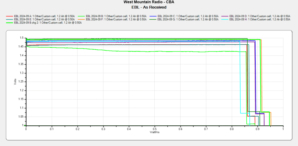
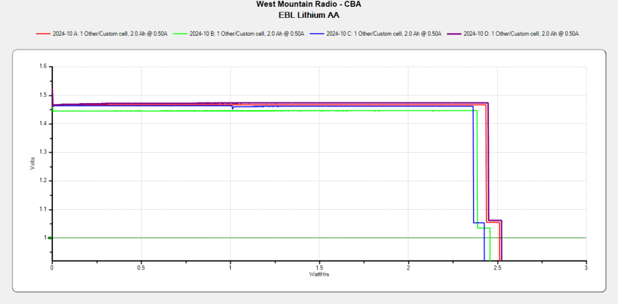
The cells claim 1200 mA·hr capacity, because it looks much more impressive than 1.2 A·hr, and deliver 900 mA·hr at 500 mA, likely higher than the scale’s actual load current.
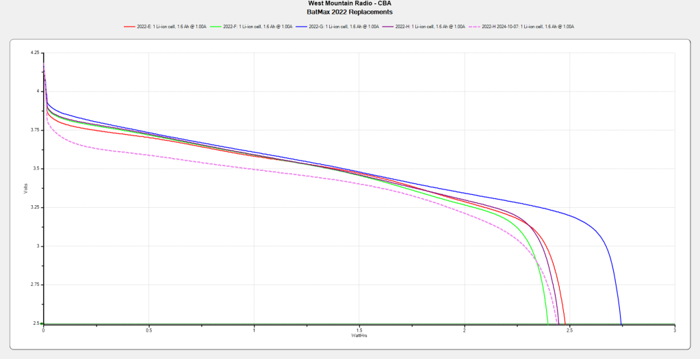
Although the total capacity remains about the same as before, the voltage depression causes the camera (which expects to run from a high-voltage lithium cell) to crash immediately after the car’s USB power jack shuts off, preventing it from properly closing the video file.
Another Batmax battery from the same batch works fine, so we’ll see if it can survive for another year.
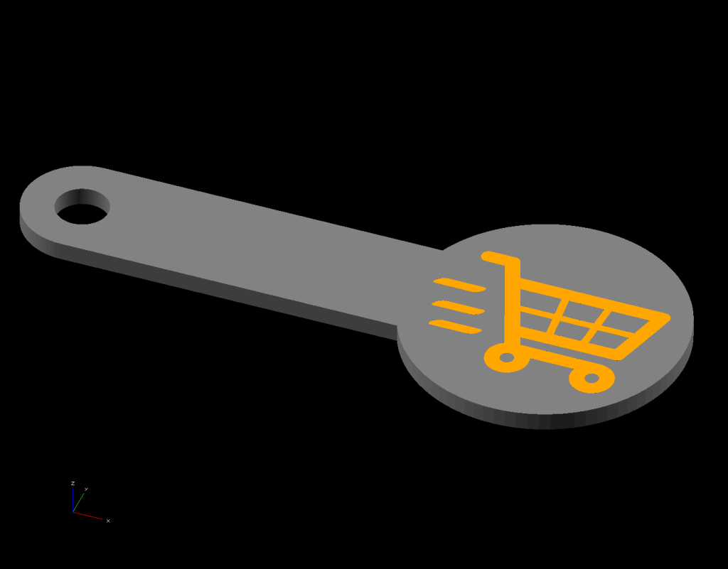
Making laser-cut cart coins is much faster than 3D printing
The LightBurn layout looks like this:
Cart coin – LightBurn screen shot
The red lines show cuts through the material to produce the overall shape with a hole for a keyring. The black areas show where the laser will raster-scan the surface at lower power to engrave the cart logo, which consists of vector outlines traced from a PNG file.
Presumably the other elements are still in there, but they’re hidden inside the outline and can’t be manipulated separately in OpenSCAD.
OpenSCAD can pick out named elements, groups, or layers from the SVG file, but, alas, the LightBurn SVG file has no named items, as shown in this chunk:
So I copied that LightBurn design to put the shapes on two different layers marked for Fill processing:
The coin-with-handle
The cart logo
It’s not absolutely necessary to use Fill layers, but they make it easier for me to visualize the shapes as solid objects.
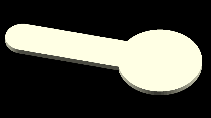
Subtracting the keyring hole and the cart logo from the overall coin-with-handle produces a single shape (with holes) for one material, plus the logo shapes in another material:
Cart coin – separated – LightBurn screen shot
Put the logo back in position before proceeding:
Cart coin – overlaid – LightBurn screen shot
Unlike the first LightBurn layout, these two layers won’t cut & engrave a cart coin: they define the shapes in such a way that OpenSCAD can turn them into 3D solid models. It’s straightforward to convert between those layouts and they can reside in the same LightBurn file as the original design; just select the one you want to burn or export, as needed.
Note that LightBurn and Inkscape use the term “layer” in completely different ways:
A LightBurn layer defines the laser control settings for all the geometry in that layer
An Inkscape layer collects a bunch of shapes into a logical group, but does not otherwise influence them
In particular, even though we now have objects in two different layers, the exported LightBurn SVG file still has no names for those layers. Fixing that requires a trip through Inkscape.
Export the filled layout from LightBurn and open (or import) that SVG file with Inkscape, which automagically names the paths:
Inkscape auto-generated path names
In order from 5 down to 1, those paths correspond to:
The cart logo
Three go-fast stripes
The coin-with-handle outline with various holes
Create two layers with memorable names, then move the appropriate paths into those layers:
Cart Coin – Inkscape layer definitions
Save the Inkscape layout as an Inkscape SVG file, which will have contents something like this snippet:
Note the inkscape:label="Coin" and inkscape:label="Logo" stanzas corresponding to the layers.
Import that SVG file into OpenSCAD twice, once to extract each layer by name, extrude the 2D shapes to form a solid model with two parts, and give them distinctive colors:
The cart logo exactly fills the matching holes in the coin shape, but because it’s a different OpenSCAD object, it won’t merge with its surroundings.
Export that model in 3mf format, because it seems better than stl for multi-material models, import it into PrusaSlicer, and get a helpful alert:
PrusaSlicer multi-material alert
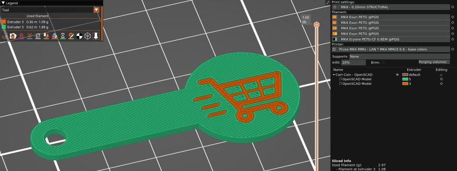
Yes, do that thing, then assign the appropriate filament to each object:
PrusaSlicer cart coin preview
Arrange half a dozen instances on the platform and make yourself a set of cart coins:
Blue cart coins on platform
Now, the obvious question: “Why not just do this in Inkscape, set up all the layers for OpenSCAD, then also export the geometry to LightBurn?”
LightBurn recently announced that Version 1.7 will be the last to support Linux, because Linux amounts to 1% of their users and we just don’t produce enough revenue to justify any effort to support us.
I don’t see standing up a Windows 11 box in the Basement Shop just to drive the laser and there is no way I’ll start running Windows as my daily driver just to design layouts in LightBurn. So, yes, I expect over the next year I’ll be transitioning away from LightBurn to Inkscape + Visicut, even though the latter has some rough edges.
I finally got around to replacing the Forester’s taillight bulbs:
Subaru Forester taillight bulbs
The clear bulbs don’t have the same thermal damage as the headlights I replaced a year ago, but the new bulbs should be much brighter.
Subaru calls them W21/5W and WY21W, respectively, but the rest of the world says 7443 and 7440NA (or 7440A).
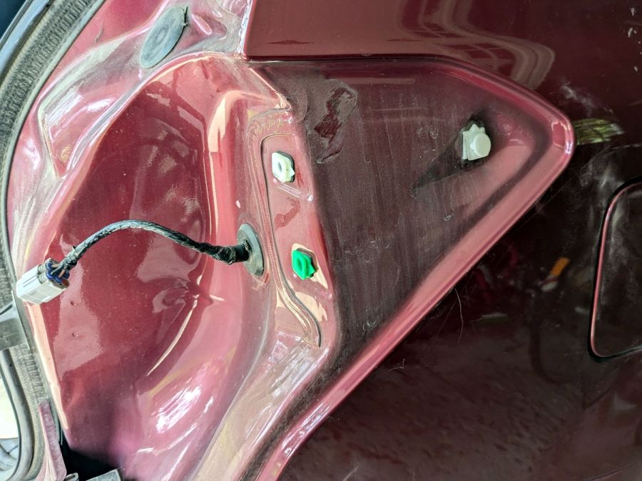
For the record, the taillight assembly comes off (after removing the obvious pair of screws not shown here) by pulling straight back with grippy gloves:
Subaru Forester taillight mount
Aligning the locating pins with those two latching sockets (why is one green?) requires a flashlight and a bit of dexterity, but easing the slot over the white post first helps a lot. Practice makes perfect: it’s easier on the other side of the car.
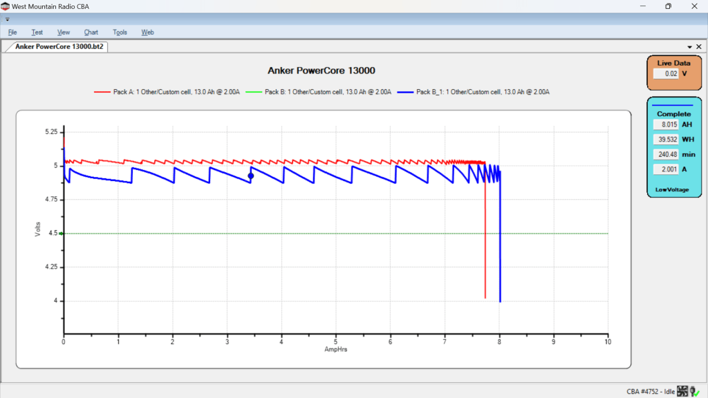
After five years of powering the action cameras on our Tour Easy recumbents, the pair of Anker A1215 PowerCore 13000 USB power banks have about 8 A·hr of capacity with a 2 A load after a full charge:
Anker PowerCore 13000 – 20204-07-26
It seems I did not test them on arrival, so I have no idea what their original capacity might have been, but I’m certain it wasn’t the 13 A·hr implied by their name.
The sawtooth voltage output looks like the internal controller picks a constant boost (or buck) ratio based on the battery voltage, then adjusts it when the output voltage falls below the lower limit. You can imagine it desperately boosting the ratio as the battery voltage falls off a cliff near the end of the curve.
I have no idea why the two packs behave so differently, although the voltages are certainly within ordinary USB limits.
They’ll continue powering the camera on my bike for a while, after which I’m sure they’ll come in handy for something …