Ed Nisley's Blog: Shop notes, electronics, firmware, machinery, 3D printing, laser cuttery, and curiosities. Contents: 100% human thinking, 0% AI slop.
I now have some difficulty accomplishing what needs to be done:
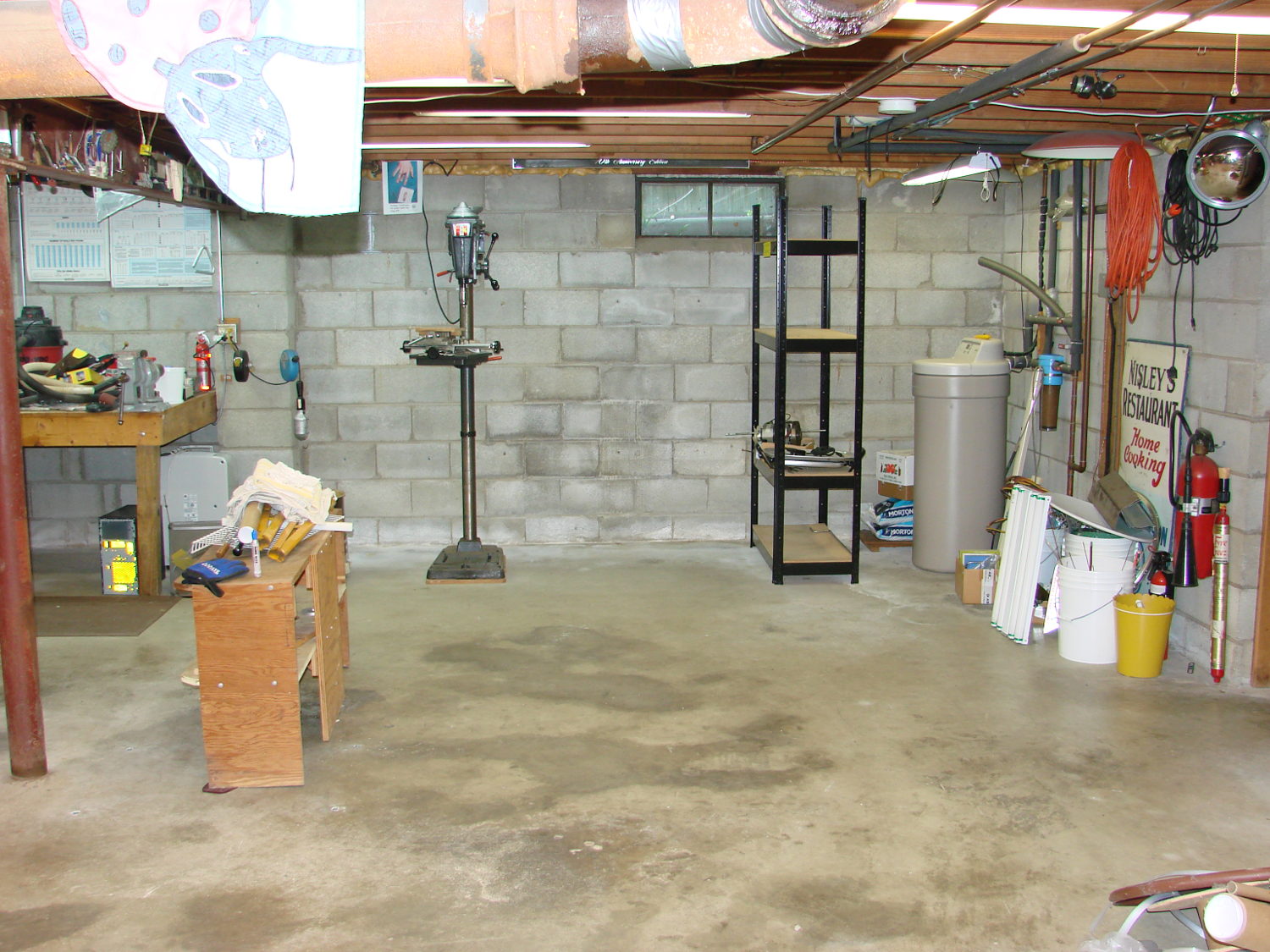
Basement Shop – right
During the rest of May I must write a pair of columns, unpack / arrange / reinstall my remaining tools / parts / toys, endure a road trip to our Larval Engineer’s graduation (*), enjoy bicycling with my Lady, and surely repair a few odds-n-ends along the way.
I’ll generate occasional posts through June, after which things should be returning to what passes for normal around here…
(*) For reasons not relevant here, our Larval Engineer’s schedule includes a final co-op and wind-up semester after “graduation”. Perhaps she’s entering the Chrysalis phase of her development?
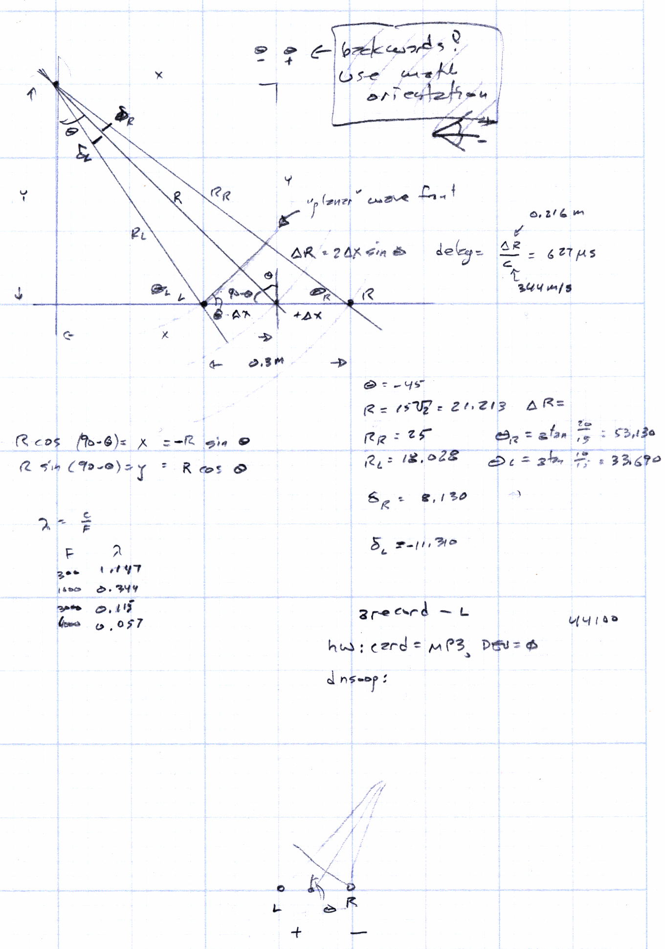
Given a point source of audio (or RF, for that matter) that’s far enough away to produce more-or-less plane wavefronts, the range difference between two microphones (or ears) is:
ΔR = (mic separation) x sin Θ
The angle lies between the perpendicular to the line from the midpoint between the mics counterclockwise to the source source: + for sounds to your left, – for sounds to your right. That’s the trig convention for angular measurement with 0° directly ahead, not the compass convention, but you can argue for either sign if you keep track of what’s going on.
The time delay between the mics, given c = speed of sound:
ΔT = ΔR / c
For microphones 300 mm apart and c = 344 m/s:
ΔT = 872 µs = 0.3 m / 344 m/s
If you delay the sound from the mic closest to the source by that amount, then add the mic signals, you get a monaural result that emphasizes, at least a little bit, sounds from that source in relation to all other sounds.
In principle, you could find the angle by listening for the loudest sound, but that’s a fool’s game.
There’s an obvious symmetry for a source on the same side, at the same angle, toward the rear.
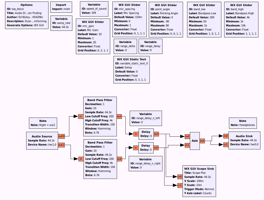
A GNU Radio data flow diagram that lets you set the angle and listen to / watch the results:
Audio Direction Finding.grc
The original doodles show it takes me a while to work around to the answer:
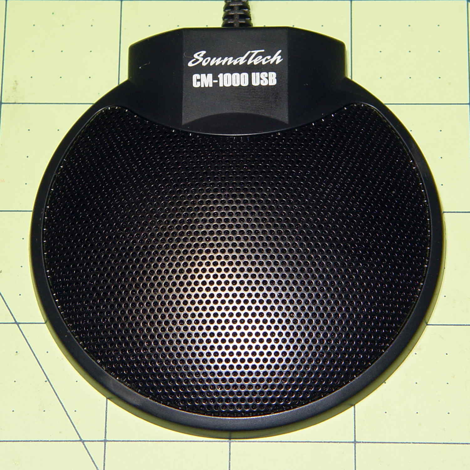
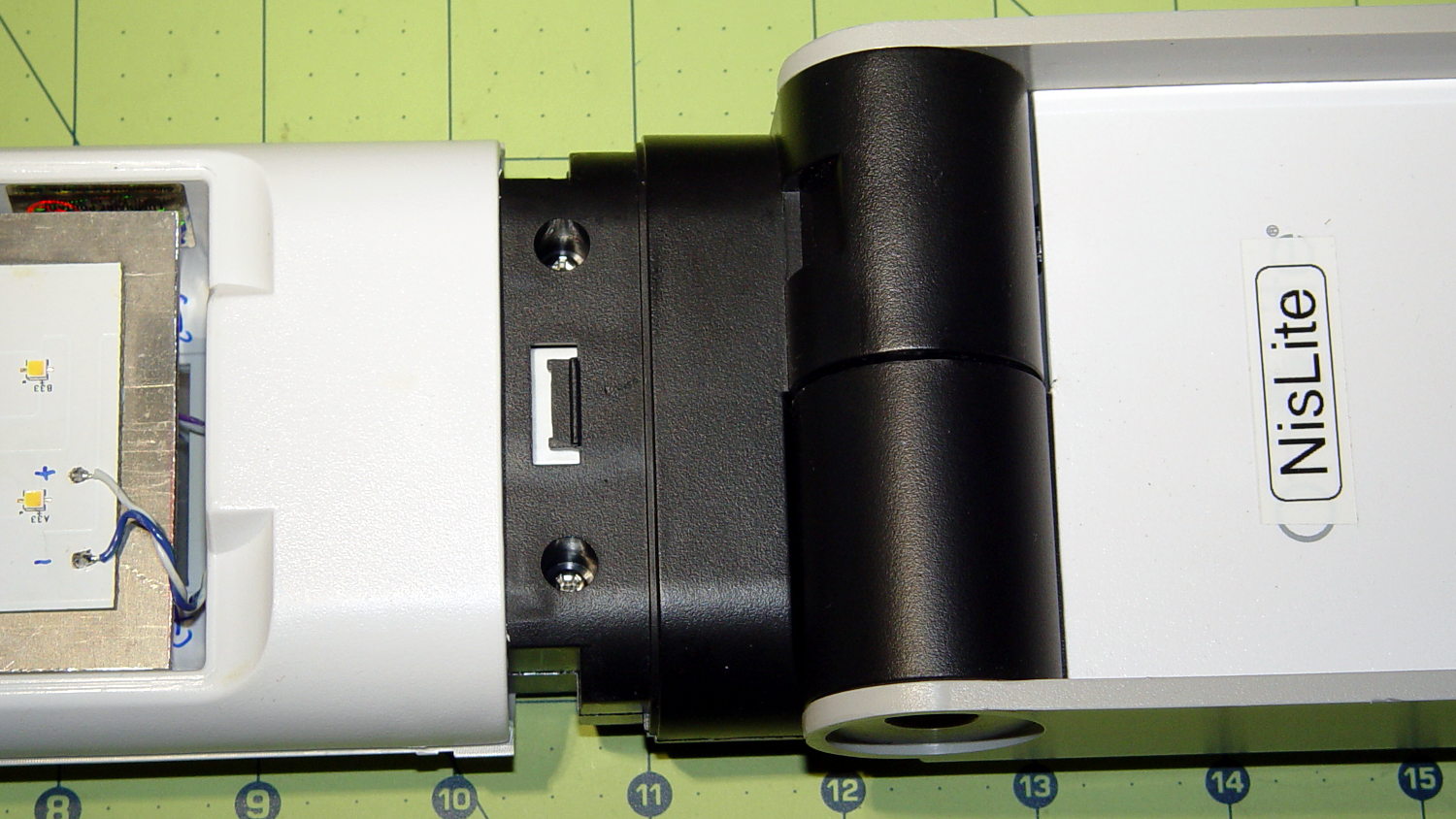
Although microphones intended for conference tables aren’t suitable for inconspicuous hearing aids, they go a long way toward working out algorithms (*). This is a SoundTech CM-1000 USB mic:
SoundTech CM-1000USB microphone
It produces noise-canceled stereo output and a quick test shows impulse sounds produce reasonable left and right responses responses; I can’t vouch for the noise cancelling part.
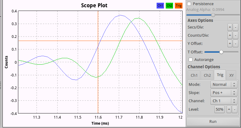
A click to the right side:
CM-1000USB mic – Right pulse
And to the left:
CM-1000USB mic – Left pulse
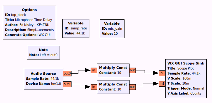
The green trace (Channel 2) is obviously the Right channel, which corresponds to in1 on the Scope Sink block and out1 of the Audio Source in the GNU Radio data flow diagram:
Microphone Time Delay.grc
There’s an irreconciliable clash between 0-index and 1-index numbering in there, but the microphone’s “Left” and “Right” channels appear in the proper places when you look at the mic from the conference room side of the label as shown in the top photo.
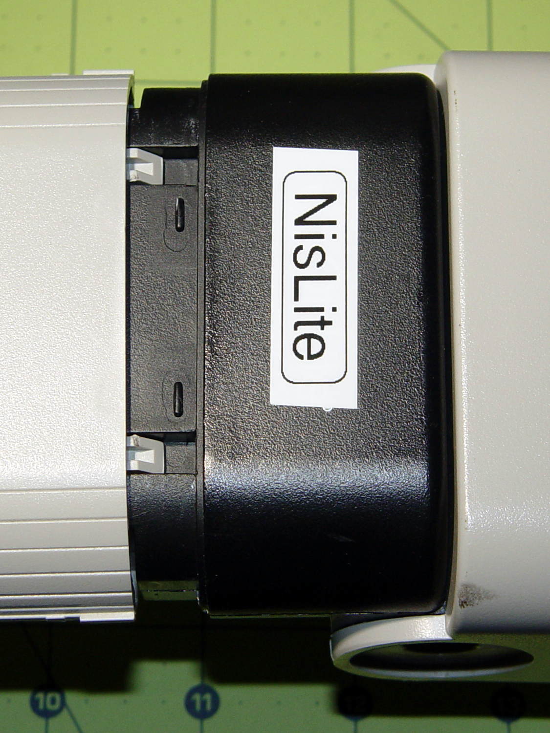
Figuring the speed of sound at 344 m/s, that 100 µs delay means the mic capsules sit 34 mm apart, which looks to be about right, as the flat part of the housing under the label spans 22 mm.
That’s a tad skimpy for things like beamforming and direction finding, so I actually bought a set with a separate CM-1000 mic that plugs into the USB mic:
SoundTech CM-1000USB and CM-1000 microphones
The channel layout diagram explains what’s supposed to happen:
Soundtouch CM-1000USB microphone channel layout
The additional mic changes the response, so that the USB unit becomes the Left channel and the analog mic provides the Right channel. I don’t know what happens to the “noise canceling” part of the story.
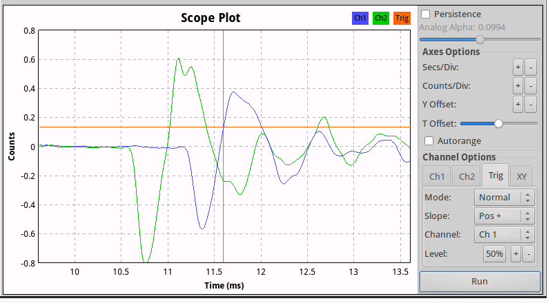
With the mics positioned 200 mm on center, a click to the right side:
SoundTech CM-1000 mics – 200 mm OC – Right pulse
The eyeballometrically precise 600 µs delay corresponds to 206 mm at 344 m/s, which might actually be close: they’re 200 mm on center, but the Right-channel mic is 10 mm smaller and the mic might be half that much further away from the other one. Not that that makes any difference.
(*) And, frankly, slapping a mic on the table won’t bother me much at all…
The audio test CD I used to measure my hearing for a Circuit Cellar project back in 2007 came to light, so I ran some tests:
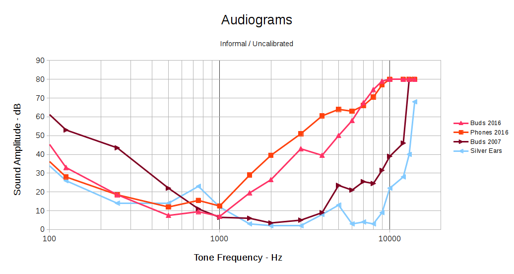
Audiograms
I don’t have an absolute level calibration for any of those curves, so they can be shifted up or down by probably 10 dB without any loss of accuracy. The overall shape matters here, not the absolute level.
The brown curve shows my hearing as of nine years ago. I built and (of course) wrote about a rather chunky low-pass shelving filter that matched the 20-ish dB difference between my midrange and treble responses, then boosted the flattened result enough for me to hear what I was missing:
Board Top
Surprisingly, it worked fairly well. That, however, was then and this is now.
The two red curves show my current response, under slightly different conditions: the “buds” curve uses the same earbuds as the 2007 curve and the “phones” curve uses over-the-ear headphones. Perhaps:
The previous (lack of) bass sensitivity came from the circuitry of the day
My bass has mysteriously improved
More likely, my midrange has gotten that much worse
The blue curve shows the response of a reference set of silver ears; the golden ears I used in 2007 were unavailable on short notice.
Given my limited bandwidth and the steep slope of that curve out toward the high end, simply fixing my (lack of) treble won’t suffice any longer: 50 dB is a lot of amplification. Compressing the bandwidth between, say, 200 Hz and 4 kHz to fit into 200 Hz to 2 kHz, then equalizing the result, might give me enough treble to get by, but it’d require re-learning how to hear.
That’s different from the straightforward frequency translation you get from a mixer. I don’t have enough audible bandwidth around 1 kHz to hear a 4 kHz slice of audio spectrum.
Back in 2007-ish, a real audiologist determined that I wasn’t “aid-able”. Maybe that’s changed.
The economics seem daunting. Michael Chorost gave a talk at Vassar lamenting the cost and terrible UX of his cochlear implants that reinforced my prejudices in that area. The discussion following my post on my Bose QC20 earphones includes useful links and rants.
The GNURadio project has enough signal-processing mojo for a nontrivial hearing aid, modulo having enough CPU power at audio frequencies. Battery power density remains the limiting factor, but I’m not nearly as fussy about appearances as most folks and some full-frontal cyborg wearables might be in order.
The converted OttLite hit the floor again and, this time, the shell around the lamp popped free. Given that I didn’t know how to take it apart before, this is new news.
There’s a small snap latch inside the bottom / inner surface:
OttLite LED Conversion – lamp shell – ventral
And two guide notches + latch nubs inside the top / outer surface:
OttLite LED Conversion – lamp shell – dorsal
So, if you had to get it apart by hand, a spudger-like tool applied to the bottom / inside of the shell and a bit of tugging should do the trick.
It snapped back together without incident, but I really must figure out a bigger base for the damn thing.
Mad Phil gave me his Brother PT-1090 labeler, which I’ve been using rather often of late. The white tape cartridge (the TZ flavor) ran out, giving me the opportunity to pry it apart:
Brother P-Touch TZ tape cartridge – disassembled
Surprisingly, a few small pins molded into the cover, plus a few obvious latches, hold it together without a trace of glue or thermal welding.
A detail of the little factory that assembles the label from several parts:
Brother P-Touch TZ tape cartridge – detail
Colored paper tape unwinds from the lower right and the top plastic layer from the lower left. Tape with thermal dye unspools from the upper left, the printhead (in the printer) heat-transfers pixels to the plastic tape in the opening right of center along the top, and the roller at the top right joins the just-printed plastic layer to the slightly sticky front surface of the paper tape. The used imaging tape respools in the gray cylinder near the middle.
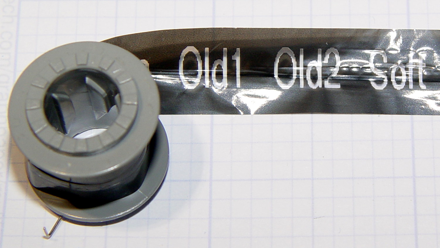
For those concerned with privacy, that gray spool of used imaging tape contains everything you’ve printed in order:
Brother P-Touch TZ tape cartridge – imaging tape
I thought the thermal dye was part of the transparent tape cover layer, but in retrospect that doesn’t make sense: the printed tape would turn black in hot environments like, say, your car. So the printer must transfer the dye from a separate tape.
The knockoff “ESD” tape cartridges from Amazon seem to have a slightly different tape path, probably to work around Brother’s patents. I’ll pry one of those apart in due course.
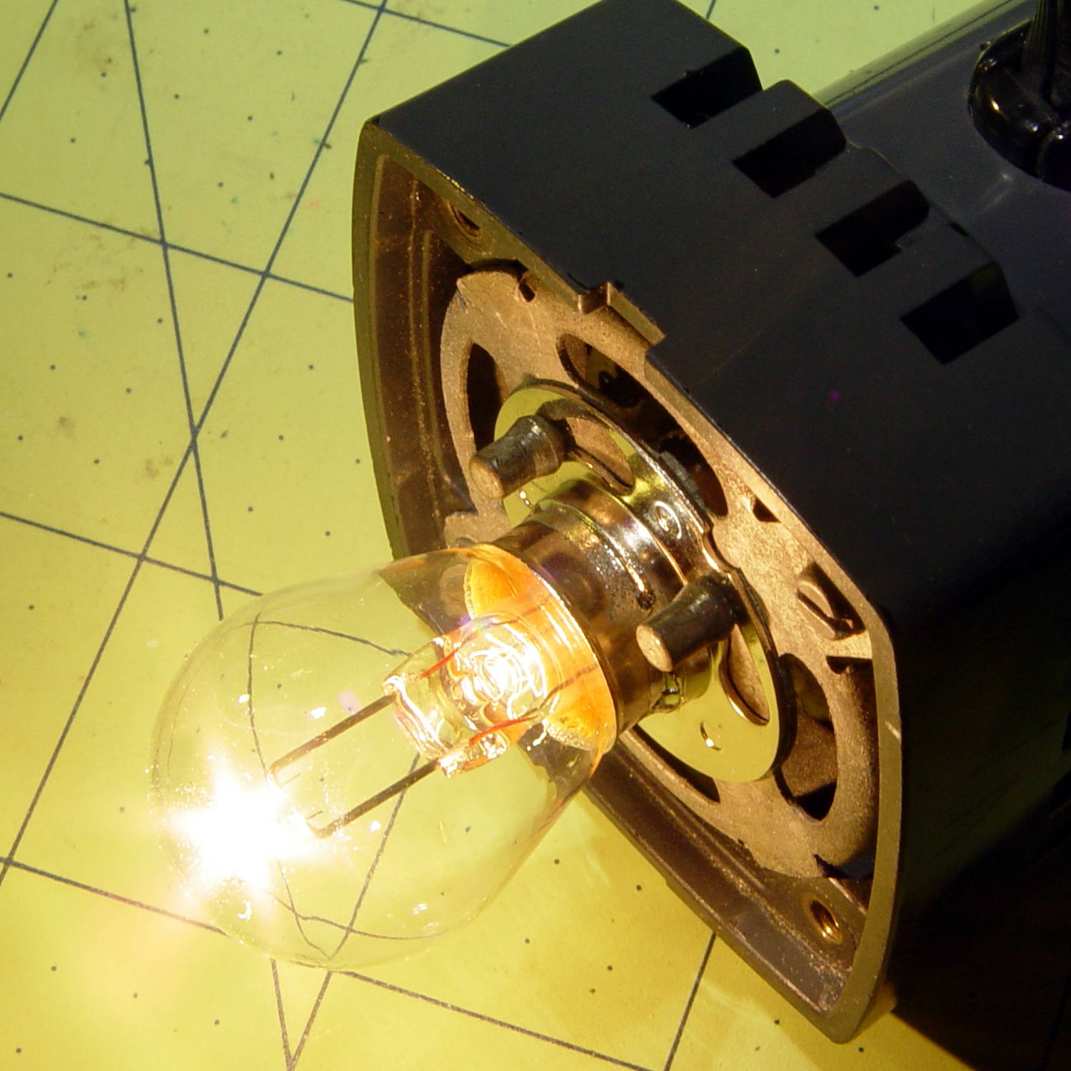
A classic American Optical microscope illuminator emerged from a box, minus its bulb. Some rummaging turned up a reference for AO bulbs, so I knew I needed a GE 1460 prefocused bulb. Those seem to be a bit rare these days, with 1460X bulbs sharing the same base with a slightly different glass envelope shape. As nearly as I can tell, as long as the filament sits in the same location relative to the base, it’s all good. Five bucks and a few days brought a new 1460X bulb to the bench, a few drops of Caig DeoxIT slicked the holder’s rather gritty contact patches, and the new bulb fit perfectly:
Microscope Illuminator – 1460X bulb – detail
And it lit up just fine, too:
Microscope Illuminator – 1460X bulb – turned on
That’s running at the lowest of three selectable voltages: 5, 6, and 7.5 VAC, respectively. Given that the bulb spec says 6.5 V (at 2.75 A!), you best have a spare bulb on hand if you need the highest setting. At the nominal 6.5 V, it’s good for 100 hours; 6 V should eke out many more hours.
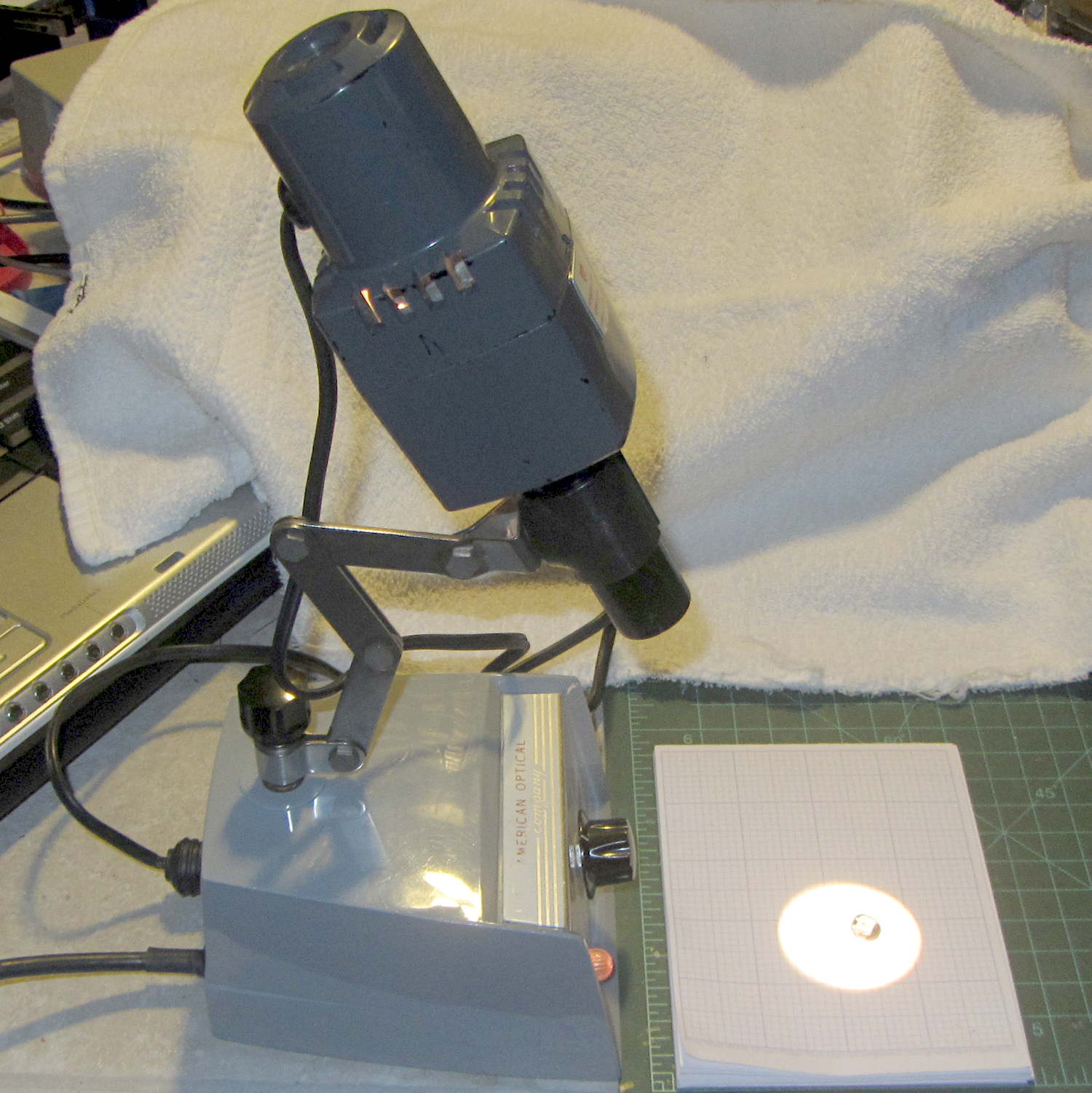
A generously articulated arm holds the illuminator for desk work:
American Optical Model 651 Microscope Illuminator – on base
That long snout fits into the pair of holes in the arm of my stereo zoom microscope to cast a bright light directly on the subject. The LED ring light makes that less necessary than before, although sometimes distinct shadows help pick out the details:
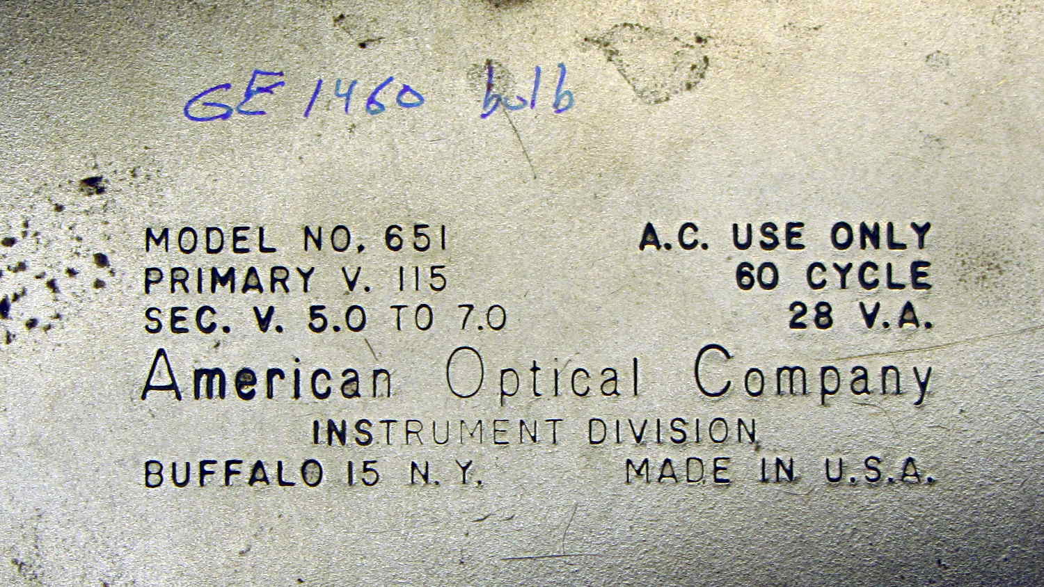
The data plate on the bottom of the illuminator, should someone need it:
American Optical Model 651 Microscope Illuminator – data plate
The optics cast an image of that white-hot filament out into space, so I think the diffuse active area of a white LED wouldn’t produce the same amount of light on the target. I have some Pirhana LEDs, though, so (when this bulb fails) I’ll see about that.