The Smell of Molten Projects in the Morning

Ed Nisley's Blog: Shop notes, electronics, firmware, machinery, 3D printing, laser cuttery, and curiosities. Contents: 100% human thinking, 0% AI slop.

Category: Electronics Workbench

Electrical & Electronic gadgets

  • S-100 Bus Computer: Capacitor Reforming

    S-100 Bus Computer: Capacitor Reforming

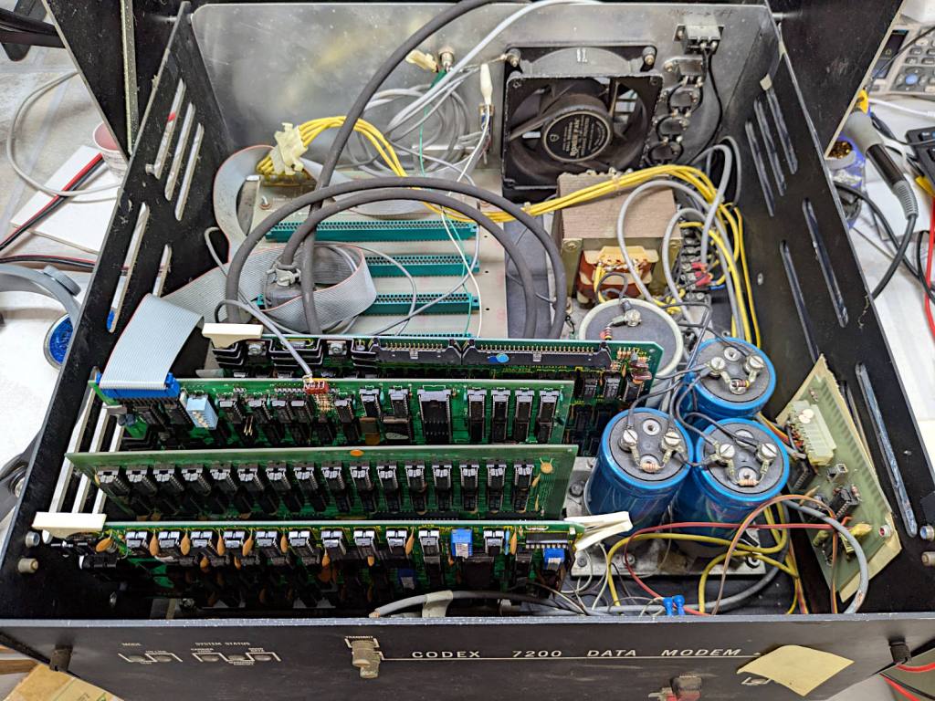
    I volunteered to reform the hulking electrolytic capacitors in a long-unused S-100 Bus computer:

    S-100 Bus Cap Reforming - Codex 7200 Modem case
    S-100 Bus Cap Reforming – Codex 7200 Modem case

    Yes, it’s built into a recycled modem case. No, they don’t make modems like they used to, either. Regrettably, the five status indicators on the left were not set up as Der Blinkenlichten.

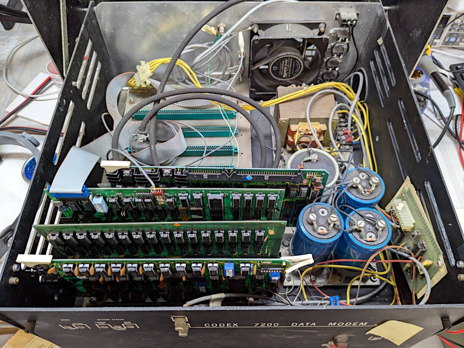
    The inside view:

    S-100 Bus Cap Reforming - inside view
    S-100 Bus Cap Reforming – inside view

    The multi-winding transformer in the back feeds bridge rectifiers (out of sight behind the caps) producing bulk DC:

    S-100 Bus Cap Reforming - bulk supply caps
    S-100 Bus Cap Reforming – bulk supply caps

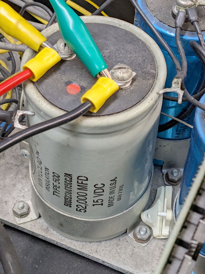
    The gray cap is 52 mF = 52000 µF 15 V for the +5 V regulators supplying the TTL logic on each board.

    Two of the three blue caps (each 9 mF = 9000 µF 50 V) are for the +12 V and -12 V supplies. I think the third cap is a separate supply for a different purpose, but I did not trace out the wiring.

    The on-board regulators seem to use solid electrolyte caps that should still be in fine shape you should replace on principle, per ericlscott’s experience. You’d want to bring up each board separately while probing the voltages; the box of stuff accompanying the system has an extender card that should make probing easier.

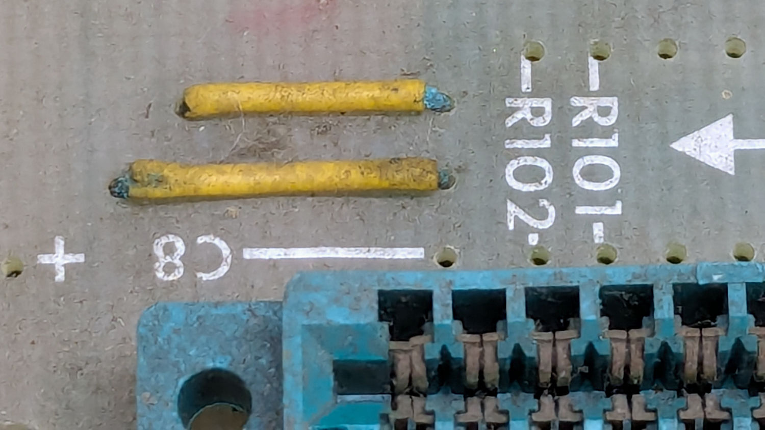
    I hoped to boot the thing after restoring the caps, but a casual inspection showed wire corrosion:

    S-100 Bus backplane - jumper wire corrosion
    S-100 Bus backplane – jumper wire corrosion

    You’d want to pull the backplane out and replace those jumpers, as well as clean the bus contacts, before applying power.

    The system has two 8 inch floppy drives in a separate case with its own power supply:

    S-100 Bus floppy drives - overview
    S-100 Bus floppy drives – overview

    There was some corrosion in there, too:

    S-100 Bus Floppy Drive - optical sensor corrosion
    S-100 Bus Floppy Drive – optical sensor corrosion

    So I confined myself to reforming the caps and must let someone with more powerful motivation restore the rest of the system before trying to connect everything and booting CP/M.

    The general idea behind “reforming” an electrolytic capacitor is to regrow the oxide layer separating the anode and cathode electrodes, which involves passing a current of about 1 mA for as long as it takes to bring the terminal voltage up to the cap’s maximum rated voltage:

    S-100 Bus Cap Reforming - 52mF 15V
    S-100 Bus Cap Reforming – 52mF 15V

    That setup consists of an absurd number of PowerPole adapters putting the meter in series with a fuseholder repurposed to hold resistors to limit the current, with leads eventually ending up on the capacitor:

    S-100 Bus Cap Reforming - 52 mF 15 V cap connection
    S-100 Bus Cap Reforming – 52 mF 15 V cap connection

    The red dot is the overpressure vent, not a polarity marker.

    Apparently the Greek mu symbol wasn’t in the font available for the labels, as all the capacitors use m in its place: that capacitor is 52 mF = 52000 µF.

    The white plastic ejection handle belongs on the right end of the CPU board seen in the second picture, which was not plugged into its slot when I opened the case. I snapped the handle in place and plugged the board in just to keep it out of trouble. The case does not have board guide slots along the edges that would let the handle eject the board, but all that was definitely in the nature of fine tuning back then.

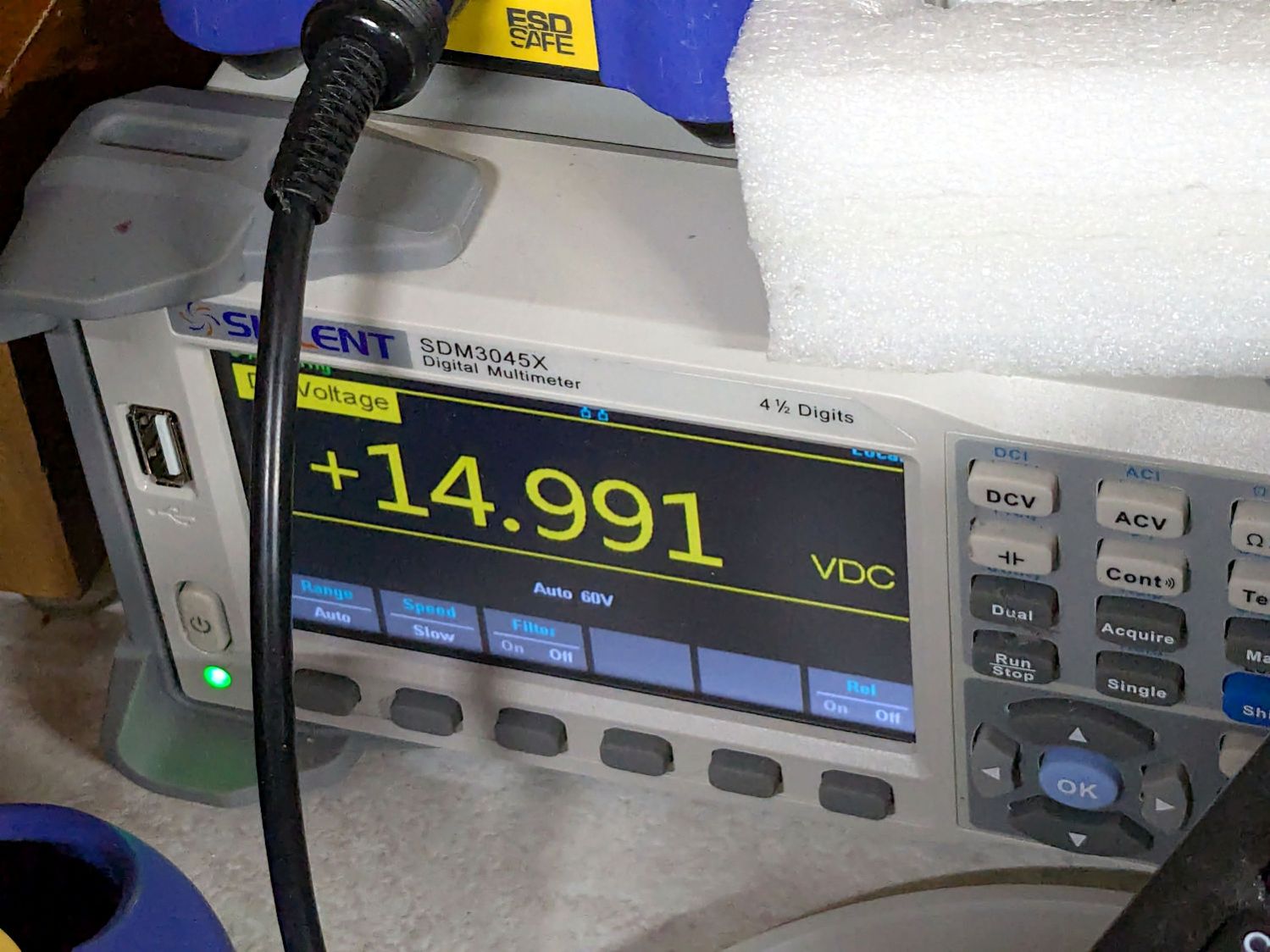
    I started with +15 V through a 16.9 kΩ resistor and swapped in 3.3 kΩ, 1 kΩ, and 220 Ω resistors as the cap voltage crept upward over the course of two days and eventually settled to a steady state:

    S-100 Bus Cap Reforming - 52mF 15V final voltage
    S-100 Bus Cap Reforming – 52mF 15V final voltage

    After discharging, the cap measured 59.5 mF with a 0.3 Ω ESR, which definitely seemed Good Enough.

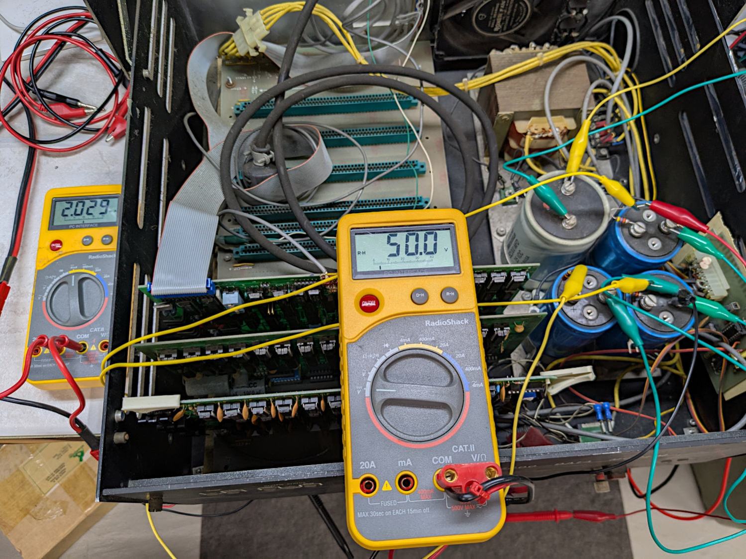
    I reformed the three 9 mF 50 V caps at the same time by applying 50 V to three resistors captured on their screw terminals, changing the resistors as the voltages rose:

    S-100 Bus Cap Reforming - 50 V caps
    S-100 Bus Cap Reforming – 50 V caps

    Those three caps eventually measured (clockwise from upper right):

    • 9.66 mF, 1.0 Ω ESR
    • 9.76 mF, 2.6 Ω ESR
    • 10.46 mF, 3.4 Ω ESR

    The ESRs suggest they’re somewhat dried out, but I’d be tempted to run them anyway, because the on-board regulators should knock down the ripple.

    All of the reformed caps had leakage currents of a few hundred microamps. They’re not new capacitors and never will be, but they may be Good Enough.

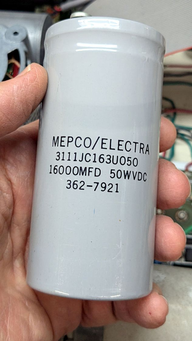
    Getting the caps out of the diskette drive power supply required easing the entire supply frame / heatsink out of the case before unscrewing the capacitor clamps:

    S-100 Bus Cap Reforming - 16 mF 50V
    S-100 Bus Cap Reforming – 16 mF 50V

    That one eventually measured 22.1 mF with 0.14 Ω ESR. Its sibling, nominally 38 mF at 15 V, came in at 48.9 mF with 0.95 Ω ESR.

    The power supply PCB carries a handful of smaller aluminum electrolytic caps that are impossible to remove without unsoldering all the TO-3 transistor leads coming through the aluminum heatsink / frame, then completely dismantling the power supply:

    S-100 Bus floppy drives - power supply PCB
    S-100 Bus floppy drives – power supply PCB

    Although I reformed the big caps, I think a better plan would be to replace the whole thing with a contemporary switching supply. AFAICT it has 24 V and 5 V outputs; because we live in the future, dual-output switchers are cheap & readily available.

    And then I closed the cases to get them ready for the next part of their adventure …

  • 7 mm Tactile Switch Pinout

    7 mm Tactile Switch Pinout

    As is usually the case, the assortment of tiny switches arrived with no pinout documentation. The 6 mm square SMD switches were easy, but the 7 mm through-hole switches posed a puzzle.

    With the switch standing to make the return spring visible as shown, the pinout looks like this:

    7mm Tactile Switch pinout
    7mm Tactile Switch pinout

    TIL, somewhat to my surprise, both the latching and momentary 7 mm switches have DPDT contacts!

    Now I know how to wire the next thing …

  • HQ Sixteen: Improved Control Cap Wiring

    HQ Sixteen: Improved Control Cap Wiring

    The new control caps on the HQ Sixteen’s handlebars have three switches apiece:

    HQ Sixteen - grip cap installed - left
    HQ Sixteen – grip cap installed – left

    A six-conductor ribbon cable brings those switch terminal through the handlebars, across the smaller PCBs where the original switches plugged in, and atop the main PCB behind / under the LCD panel where they get wired together:

    HQ Sixteen - Control Button switch cable
    HQ Sixteen – Control Button switch cable

    The gray ribbon cable carries power for the LEDs and returns the original switch signals formerly plugged into one of the four-pin headers on the right PCB. The same PCB is used on the other side and the switches over there plug into the other header.

    The central PCB is also used for the rear handlebars, which do not have the smaller PCBs, and those switch cables plug directly into four-pin headers mounted instead of the headers for the gray ribbon cables:

    HQ Sixteen - Control Button central PCB
    HQ Sixteen – Control Button central PCB

    Some probing and doodling produced a diagram of the switch connections:

    HQ Sixteen - Control Button Wiring
    HQ Sixteen – Control Button Wiring

    Working with the handlebars either inverted or flipped left-for-right on the workbench makes this far more confusing than it really should be.

    In any event, the bottom diagram shows the connections between the two four-pad header positions on the central PCB and the two six-pin headers for the new switches. I used a 2×6 pin header block to plug in the new switches, connected the pins with soldered Wire-Wrap wire, and used three-wire ribbon cable to the PCB pads.

    The general idea was to duplicate the Start-Stop and Needle Up/Down switches on both sides, while maintaining the same relative positions of the Fast / Slow switches. In effect, the two new switches on each side are wired in parallel to the original switch pads on the PCB.

    Surprisingly, I got the three-wire ribbon cables from the four-pad headers right on the second try, which involved flipping it over. The top and bottom pads on those headers are connected together, so the three-wire cable can go on either way to reverse the positions of the other two wires.

    And then the new switches Just Worked™ … whew!

  • HQ Sixteen: Improved Control Cap Final Assembly

    HQ Sixteen: Improved Control Cap Final Assembly

    My version of the Handi-Quilter HQ Sixteen grip control caps requires some assembly:

    Control Button Caps - solid model - build view
    Control Button Caps – solid model – build view

    Getting the OEM caps off the handlebars required carefully applying torque through a strap wrench, but they eventually came free:

    HQ Sixteen - OEM grip cap - screw holes
    HQ Sixteen – OEM grip cap – screw holes

    I don’t know what the unused screw hole between the two gnarly holes was for; perhaps they discovered one hole was inadequate.

    The alert reader will note the two screw holes are not the same distance from the end of the tube, which required rebuilding the plug model to match:

    Control Button Caps - solid model - plug holes
    Control Button Caps – solid model – plug holes

    Which is why I didn’t glue the plug into the cap before I got the OEM caps off.

    Redrill the tube holes to 3 mm, file the burrs from both the OEM and my drilling, smooth the edges, and the plug fit perfectly. Then I seated the M3 square nuts behind those hole and, after installing the new plugs in the handlebars, glued the caps in place with a simple fixture to ensure the front faced forward:

    - HQ Sixteen - grip cap faceplate gluingHQ Sixteen - grip cap gluing
    – HQ Sixteen – grip cap faceplate gluingHQ Sixteen – grip cap gluing

    The clamp gently compresses the foam enough to hold the flats against the bench block while the JB Plastic Bonder cures.

    After verifying all the buttons worked, I glued the faceplates to the cap bodies:

    HQ Sixteen - grip cap faceplate gluing
    HQ Sixteen – grip cap faceplate gluing

    The tape held the faceplate in place while I snugged the clamps.

    Modulo my weak graphic design skills, the caps look pretty good:

    HQ Sixteen - grip cap installed - right
    HQ Sixteen – grip cap installed – right

    And, after a bit of wiring yet to be described, the buttons do exactly what their legends suggest:

    HQ Sixteen - grip cap installed - left
    HQ Sixteen – grip cap installed – left

    The white sheet with feeble graphics can be peeled off, so I have another chance to tart it up.

    The overall idea was to replace the failing Start/Stop switch while duplicating that switch on both caps. While I was at it, I also duplicated the Needle Up/Down button, because who wants asymmetric caps?

    Mary is assembling another quilt and the new switches will get plenty of action …

  • Power Outage

    Power Outage

    This housing development was the second in Poughkeepsie to have underground utilities and, to put it mildly, a lot has rotted out over the last 70 years.

    Over the weekend, one phase of the AC power flickered and eventually failed completely, with the other phase supplying a steady 120 VAC. Central Hudson (Gas & Electric) crews located long-lost buried boxes in places not matching their maps:

    Power Outage - flooded box
    Power Outage – flooded box

    Then they pumped / bailed enough water to repair / lengthen the wires:

    Power Outage - corroded wiring
    Power Outage – corroded wiring

    I’ve never before seen anybody work on live wires underwater.

    They installed above-ground boxes to simplify The Next Time.

    Some improvisation was required:

    Power Outage - improvised cocoa stirring
    Power Outage – improvised cocoa stirring

    Gotta say, cold Fireball Cocoa tastes different than hot Fireball Cocoa.

  • HQ Sixteen: Handlebar Control Button Caps

    HQ Sixteen: Handlebar Control Button Caps

    Each of the HQ Sixteen’s handlebars has a cap with control buttons:

    HQ Sixteen control caps - side view
    HQ Sixteen control caps – side view

    The left cap:

    HQ Sixteen control caps - left
    HQ Sixteen control caps – left

    The right cap:

    HQ Sixteen control caps - OEM right
    HQ Sixteen control caps – OEM right

    The membrane switch overlay has textured bumps, although both of us have trouble finding them.

    The Start / Stop switch gets the most use and, as you’d expect, has become intermittent after two decades of use.

    Mary thinks a Start / Stop switch on both caps would be an improvement, letting her position quilting rulers with her right hand and run the machine with her left hand & thumb. I don’t know how the switches are wired, but the wiring suggests either simple single-bit inputs or a small matrix.

    She also finds membrane switches difficult to press, so I’m in the process of replacing the control caps with something more to her liking.

    The current concept goes a little something like this:

    HQ Sixteen control caps - new caps
    HQ Sixteen control caps – new caps

    Stipulated: my art hand is weak.

    Those are little bitty SMD switches:

    HQ Sixteen control caps - new caps overview
    HQ Sixteen control caps – new caps overview

    They’re easy to locate by touch, with a stem length chosen to “feel right” when pushed.

    They have been grievously misapplied:

    HQ Sixteen control caps - switches
    HQ Sixteen control caps – switches

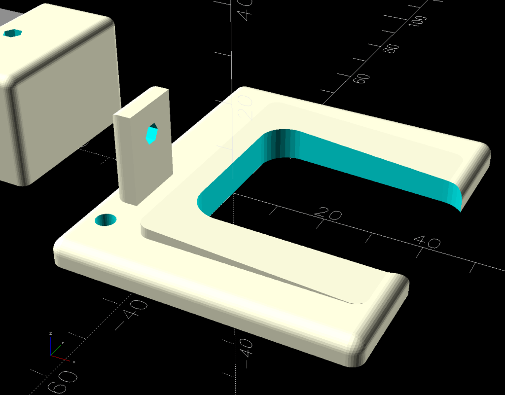
    The solid model has three main pieces and a lock for the ribbon cable:

    Control Button Caps - solid model - build view
    Control Button Caps – solid model – build view

    Those pockets keep the switches oriented while the glue cures.

    Two screws through the handlebar secure each cap. Handi-Quilter drove sheet metal screws into their OEM caps, distorting them enough to jam solidly into the handlebars. I’ve been reluctant to apply enough force to loosen them, so they remain frozen in place until the current quilt is done.

    The new plugs have recesses for M3 square nuts to make them easily removable. As with the handlebar angle adapters, I’ll glue the plugs into the caps.

    A slightly exploded view shows how the pieces fit together:

    Control Button Caps - solid model - show view gapped
    Control Button Caps – solid model – show view gapped

    The switch plate sits recessed into the cap to allow room for the label (about which, more later):

    Control Button Caps - solid model - show view assembled
    Control Button Caps – solid model – show view assembled

    The OpenSCAD source code as a GitHub Gist:

    // Handiquilter HQ Sixteen handlebar control button caps
    // Ed Nisley – KE4ZNU
    // 2025-04-05
    include <BOSL2/std.scad>
    Layout = "Show"; // [Show,Build,Grip,Body,Face,FaceBack,Plug,CableLock]
    // Angle w.r.t. handlebar
    FaceAngle = 30; // [10:45]
    // Separation in Show display
    Gap = 5; // [0:20]
    /* [Hidden] */
    HoleWindage = 0.2;
    Protrusion = 0.1;
    NumSides = 2*3*4;
    WallThick = 3.0;
    ID = 0;
    OD = 1;
    LENGTH = 2;
    Grip = [19.7,22.4,15.0]; // (7/8)*INCH = 22.2 mm + roughness, LENGTH=OEM insertion depth
    GripRadius = Grip[OD]/2;
    FoamOD = 34.0; // handlebar foam
    FoamRadius = FoamOD/2;
    SwitchBody = [6.3,6.3,4.0]; // does not include SMD leads
    SwitchStemOD = 3.5 + 2*HoleWindage;
    SwitchOC = 10.0; // center-to-center switch spacing
    LabelThick = 0.5; // laminated overlay
    FaceRim = 2.0; // rim around faceplate
    FaceThick = 2.0; // … plate thickness
    FaceDepth = FaceThick + LabelThick; // inset allowing for faceplate label
    CapOD = 38.0; // overall cap diameter
    CapTrim = FoamRadius; // flat trim on front
    CapBase = 5.0; // bottom thickness
    Cap = [FoamOD – FaceRim,CapOD,CapBase + CapOD*tan(FaceAngle)];
    echo(Cap=Cap);
    TargetSize = 4.0; // laser alignment targets
    TargetsOC = [40.0,40.0];
    Cable = [10.0,2.0,WallThick]; // aperture for cable lock
    ScrewAngles = [-45,45]; // mounting screws
    Screw = [2.0,3.0,7.0]; // OEM = sheet metal screw
    ScrewOffset = 6.0; // from top of grip tube
    SquareNut = [3.0,5.5,2.3 + 0.4]; // M3 square nut OD = side, LENGTH + inset allowance
    NutInset = GripRadius – sqrt(pow(GripRadius,2) – pow(SquareNut[OD],2)/4);
    PlugOA = [(Grip[ID] – 2*WallThick),(Grip[ID] – 1.0),(CapBase + ScrewOffset + 10.0)];
    echo(PlugOA=PlugOA);
    //———-
    // Define objects
    //—–
    // Handlebar tube
    module GripTube() {
    difference() {
    tube(3*Grip[LENGTH],GripRadius,Grip[ID]/2,anchor=TOP);
    for (a = ScrewAngles) {
    down(ScrewOffset) zrot(a-90)
    right(GripRadius)
    yrot(90) cylinder(d=Screw[OD],h=Screw[LENGTH],center=true,$fn=6);
    }
    }
    }
    //—–
    // SVG outline of faceplate for laser cuttery
    module FaceShape(Holes=true,Targets=false) {
    difference() {
    scale([1,1/cos(FaceAngle)])
    difference() {
    circle(d=(Cap[OD] – 2*FaceRim),$fn=144);
    fwd(CapTrim – FaceRim)
    square(Cap[OD],anchor=BACK);
    }
    if (Holes)
    for (i=[-1:1]) // arrange switch stem holes
    right(i*SwitchOC)
    zrot(180/8) circle(d=SwitchStemOD,$fn=32);
    }
    if (Targets)
    for (i = [-1,1], j = [-1,1])
    translate([i*TargetsOC.x/2,j*TargetsOC.y/2])
    square(2.0,center=true);
    }
    //—–
    // Faceplate backing sheet
    // Switch bodies indented into bottom, so flip to build
    module FacePlate(Thick=FaceThick,Holes=true) {
    difference() {
    linear_extrude(height=Thick,convexity=5)
    FaceShape(Holes);
    up(SwitchBody.z/4)
    for (i = [-1:1])
    right(i*SwitchOC)
    cube(SwitchBody,anchor=TOP);
    }
    }
    //—–
    // Cap body
    module CapBody() {
    $fn=48;
    up(CapBase + (Cap[OD]/2)*tan(FaceAngle)) xrot(FaceAngle)
    difference() {
    xrot(-FaceAngle)
    down(CapBase + (Cap[OD]/2)*tan(FaceAngle))
    difference() {
    cylinder(d=Cap[OD],h=Cap[LENGTH]);
    fwd(CapTrim) down(Protrusion)
    cube(2*Cap[LENGTH],anchor=BACK+BOTTOM);
    up(CapBase)
    difference() {
    cylinder(d=Cap[ID],h=Cap[LENGTH]);
    fwd(CapTrim – 2*FaceRim)
    cube(2*Cap[LENGTH],anchor=BACK+BOTTOM);
    }
    down(Protrusion)
    cylinder(d=Grip[ID],h=Cap[LENGTH]);
    }
    cube(2*Cap[OD],anchor=BOTTOM);
    down(FaceDepth)
    FacePlate(FaceDepth + Protrusion,Holes=false);
    }
    }
    //—–
    // Plug going into grip handlebar
    module CapPlug() {
    $fn=48;
    difference() {
    tube(PlugOA[LENGTH],id=PlugOA[ID],od=PlugOA[OD],anchor=BOTTOM)
    position(TOP)
    tube(CapBase,id=PlugOA[ID],od=Grip[ID],anchor=TOP);
    for (a = ScrewAngles)
    up(PlugOA.z – CapBase – ScrewOffset) zrot(a-90)
    right(PlugOA[ID]/2)
    yrot(90) {
    cube([SquareNut[OD],SquareNut[OD],SquareNut[LENGTH] + NutInset],center=true);
    zrot(180/6)
    cylinder(d=(SquareNut[ID] + 2*HoleWindage),h=PlugOA[ID],center=true,$fn=6);
    }
    }
    }
    //—–
    // Lock plate for ribbon cable
    module CableLock() {
    difference() {
    cuboid([2*Cable.x,PlugOA[ID],WallThick],rounding=WallThick/2,anchor=BOTTOM);
    for (j = [-1,1])
    back(j*Cable.y) down(Protrusion)
    cube(Cable + [0,0,2*Protrusion],anchor=BOTTOM);
    }
    }
    //———-
    // Build things
    if (Layout == "Grip") {
    color("Silver",0.5)
    GripTube();
    }
    if (Layout == "Face")
    FaceShape(Targets=true);
    if (Layout == "FaceBack")
    FacePlate();
    if (Layout == "Body")
    CapBody();
    if (Layout == "Plug")
    CapPlug();
    if (Layout == "CableLock")
    CableLock();
    if (Layout == "Show") {
    color("Green")
    up(CapBase)
    CableLock();
    color("Orange")
    down(Gap)
    down(PlugOA[LENGTH] – CapBase)
    CapPlug();
    color("Cyan",(Gap > 4)? 1.0 : 0.2)
    CapBody();
    color("White",(Gap > 4)? 1.0 : 0.5)
    up(Gap*cos(FaceAngle)) fwd(Gap*sin(FaceAngle))
    up(CapBase + (Cap[OD]/2)*tan(FaceAngle) – FaceDepth)
    back(FaceDepth*sin(FaceAngle)) xrot(FaceAngle)
    FacePlate();
    down(3*Gap) {
    color("Silver",0.5)
    GripTube();
    down(Gap)
    color("Gray",0.5)
    tube(3*Grip[LENGTH],FoamRadius,Grip[OD]/2,anchor=TOP);
    }
    }
    if (Layout == "Build") {
    right((Gap + Cap[OD])/2)
    CapBody();
    left((Gap + Cap[OD])/2)
    zrot(180) up(FaceThick) xrot(180)
    FacePlate();
    fwd(Gap + Cap[OD])
    up(PlugOA[LENGTH]) xrot(180) zrot(180)
    CapPlug();
    fwd(Cap[OD]/2)
    zrot(90)
    CableLock();
    }

  • Wrights SideWinder Bobbin Winder: Laying On Of Hands

    Wrights SideWinder Bobbin Winder: Laying On Of Hands

    Mary attempted to wind a bobbin using the Wrights SideWinder Bobbin Winder she got from a friend:

    Sidewinder bobbin winder - top
    Sidewinder bobbin winder – top

    The URL in the instructions is dead, but the Sidewinder lives on as the Simplicity SideWinder Portable Bobbin Winder:

    Simplicity Sidewinder Bobbin Winder
    Simplicity Sidewinder Bobbin Winder

    Looks kinda pallid to me, too, although hardcore BarbieCore is also most definitely not our thing.

    Anyhow, the motor didn’t even twitch when pressing the button, so after I verified the two AA alkaline cells were Just Fine, I laid it on the Electronics Bench and popped the top to see what was the matter:

    Sidewinder bobbin winder - interior wiring
    Sidewinder bobbin winder – interior wiring

    For the record, the red and black wires at the battery compartment are exactly reversed from what you might expect based on, say, the colors of your multimeter probes. I know better, but it comes as a surprise every time.

    The pushbutton switch pulls in the relay (red block in the middle), which latches on until the bobbin fills and the accumulated thread lifts the finger riding on the bobbin to rotate the white cam (under the motor), thus opening the switch (black block), releasing the relay, and shutting off the motor.

    Which, of course, worked perfectly after I stuck the alkalines back in place on the bench and poked the button to watch the proceedings.

    It’s all back together again and continues to run, so I’ll declare victory until the next time she fills a bobbin and, predictably, it doesn’t start.