The Smell of Molten Projects in the Morning

Ed Nisley's Blog: Shop notes, electronics, firmware, machinery, 3D printing, laser cuttery, and curiosities. Contents: 100% human thinking, 0% AI slop.

Category: Electronics Workbench

Electrical & Electronic gadgets

  • SJCAM M50 Trail Camera: Power Supply FAIL

    SJCAM M50 Trail Camera: Power Supply FAIL

    The power supply converting the battery’s raw 6 V into whatever voltage is required by my troublesome SJCAM M50 trail camera failed, despite the replaced wire between the battery and the camera remaining intact. The camera continued to work with 5 V power supplied through its USB-C jack, so I think it can accomplish most of its goals with a USB battery pack nearby.

    Unfortunately, the USB-C jack isn’t accessible with the case closed, so I decided to repurpose the battery compartment’s external 6 V input jack.

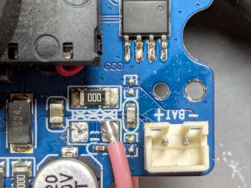
    I removed the 000 (0 Ω) SMD “resistor” connecting the battery + terminal to the power supply circuitry and soldered one end of a wire to that pad:

    SJCAM M50 - battery input pad
    SJCAM M50 – battery input pad

    The adjacent 000 “resistor” connects the battery - input terminal to the circuit, so it remains in place.

    The other end of the wire goes to the high side of the +5 V filter caps for the USB-C input:

    SJCAM M50 - USB power input pad
    SJCAM M50 – USB power input pad

    The battery pack produced 6 V from two parallel-ish banks of four AA cells or an external source arriving through a 3.5 / 1.35 mm coaxial power plug, with a Schottky diode dropping 250 mV before reaching the BAT connector in the first picture. The camera seems happy to run from slightly under 5 V.

    Unfortunately, “happy to run” means the camera remains in Setup mode, ready to dump its stored images through the USB port, and won’t take pictures regardless of the switch normally controlling such things. It seems I must either troubleshoot the switching regulator generating the internal power supply voltage(s)or junk the camera.

    I’m not red-hot pleased with the several SJCAM cameras I’ve used, as they seem to feature under-designed durability for their intended use. The fact that SJCAM cameras seem to be on the better side of a bad lot is not comforting.

    I did the probing & doodling during a Squidwrench remote meeting and was assured I would not regret directly applying five volts to the circuit, said with the intonation of this meme:

    You will certainly not regret 67 amps
    You will certainly not regret 67 amps

    Nah, I’ve never done anything like that …

  • HQ Sixteen: Nose Ring Lights

    HQ Sixteen: Nose Ring Lights

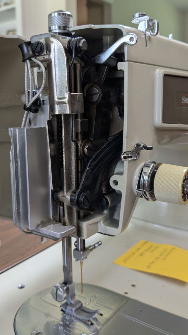
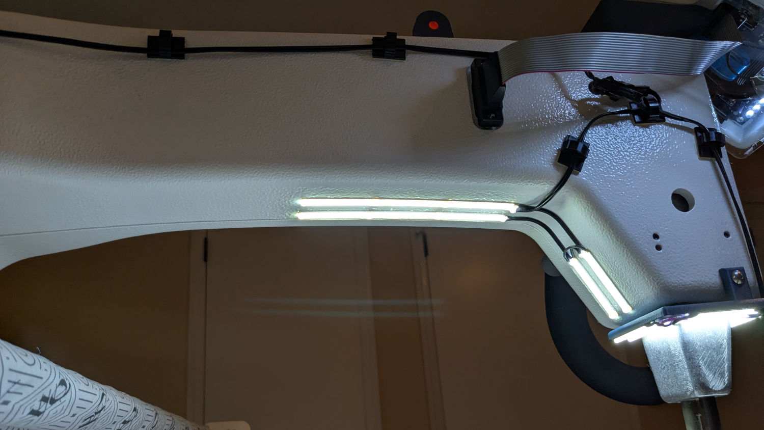
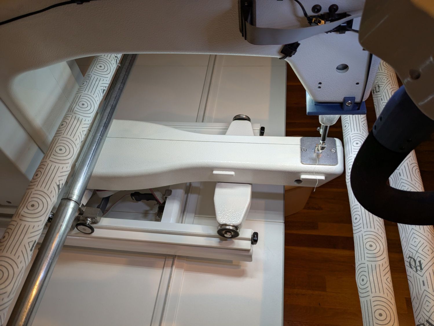
    We don’t know what the proper term might be for this part of the machine, but it looks sorta like a nose and the lights form most of a ring around it, so I’m going with “Nose Ring Lights”:

    HQ Sixteen Nose Ring lights - front view
    HQ Sixteen Nose Ring lights – front view

    The general idea is to put more light on the quilt than the Chin Light, which looked pretty good until the COB LED strip started flickering as the LEDs failed.

    Handi-Quilter sells a ring light for machines manufactured a decade later than ours, but it uses a built-in USB jack this machine lacks.

    One of two (apparently) unused M4 holes on the left side of the machine frame suggested a mounting point for a 3D printed bracket:

    HQ Sixteen Nose Ring Lights - solid model
    HQ Sixteen Nose Ring Lights – solid model

    The ramp matches the 3° (-ish) mold draft of the machine frame, which I initially ignored by angling the tab, but a tilted frame looked awful; it’s now aligned with local horizontal..

    A few iterations got all the pieces & holes in their proper places:

    HQ Sixteen Nose Ring lights - iterations
    HQ Sixteen Nose Ring lights – iterations

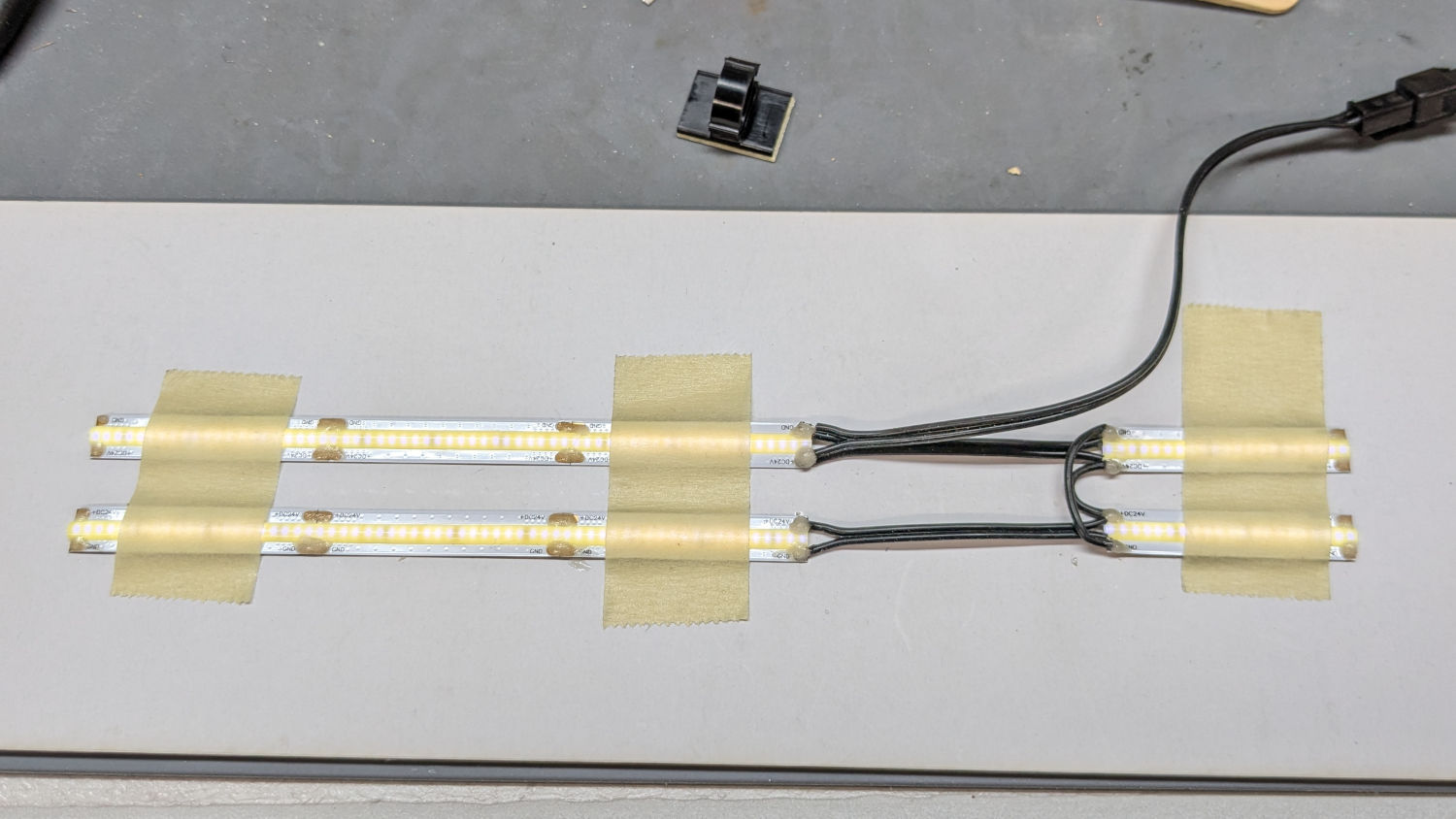
    The smaller (rampless) bracket has three LED strips, but a quick test showed more light would be better:

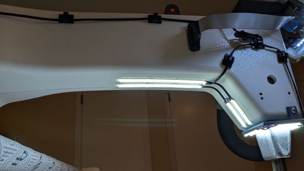
    HQ Sixteen Nose Ring lights - bottom view
    HQ Sixteen Nose Ring lights – bottom view

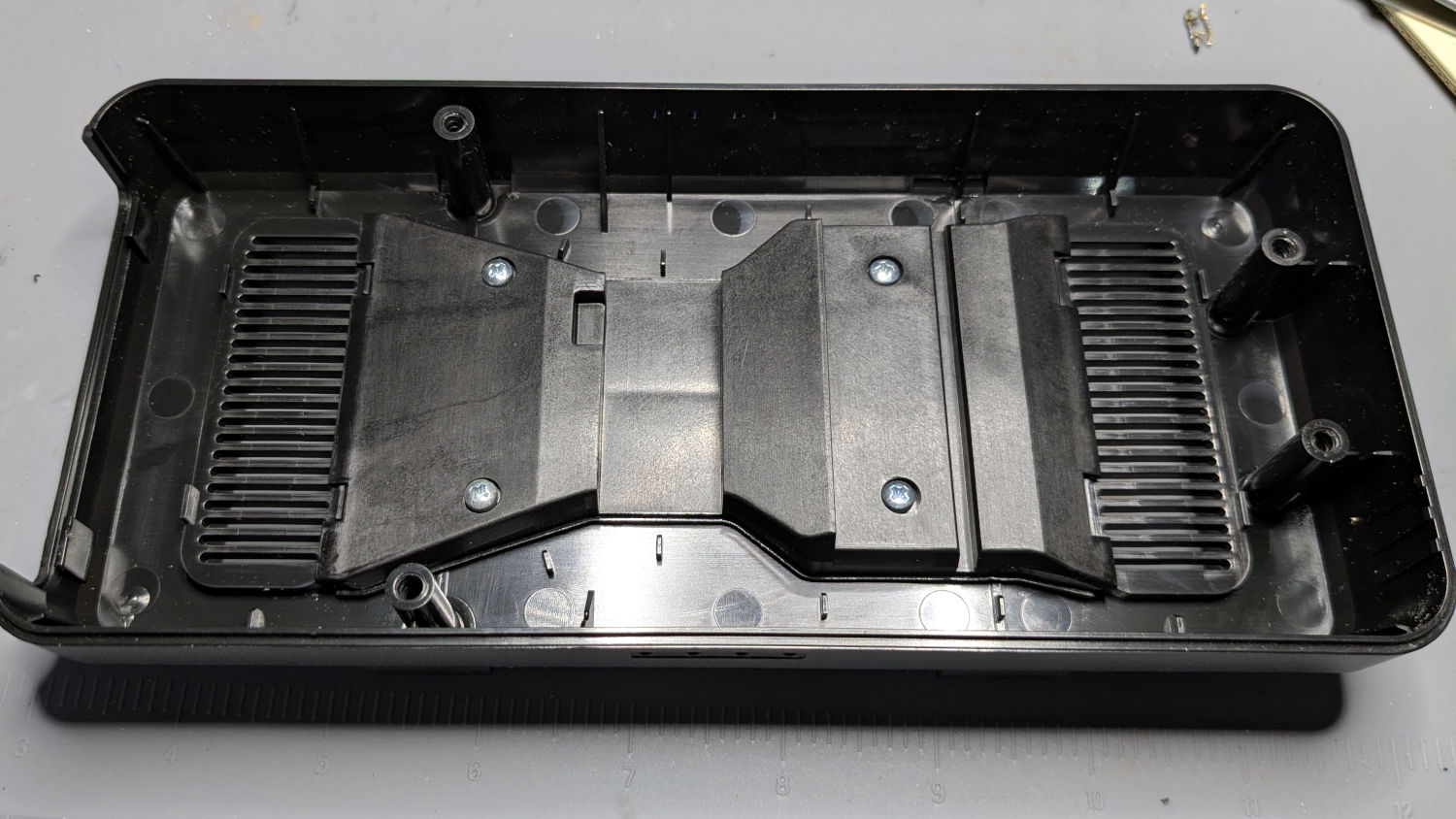
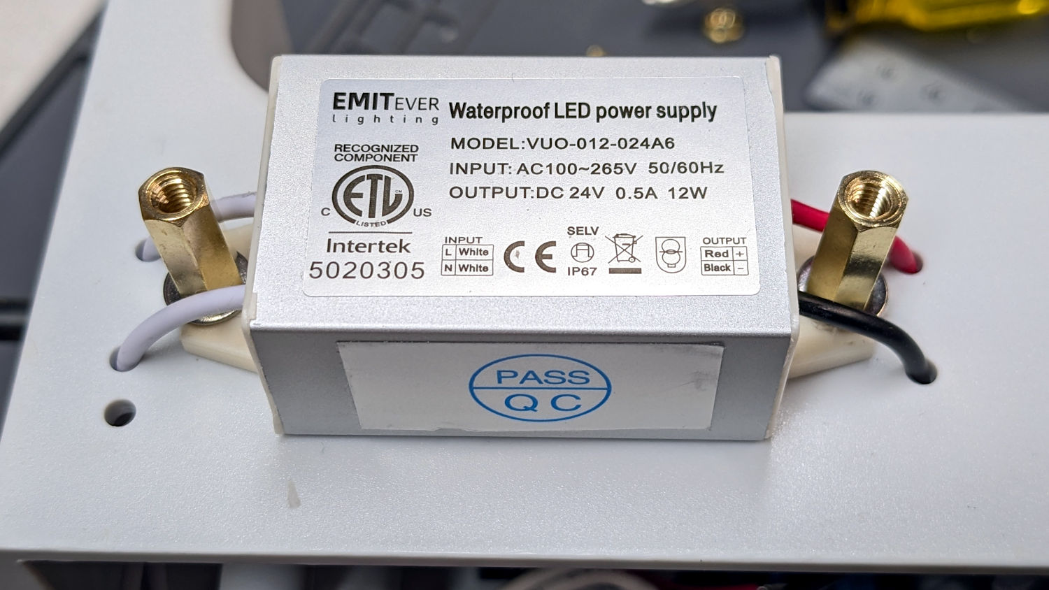
    The lack of a transparent-ish cover is obviously unsuitable for a commercial product, but the key design goal is to not interfere with spreading as much light as possible across as much of the quilt as possible. The black JB Weld Plastic Bonder blobs keep the 24 VDC supply out of harm’s way, which is as good as it needs to be for now.

    The bracket has three sides, because the right side of the machine has all the thread guide hardware. Putting anything over there seemed likely to interfere with either thread movement or fingers making adjustments.

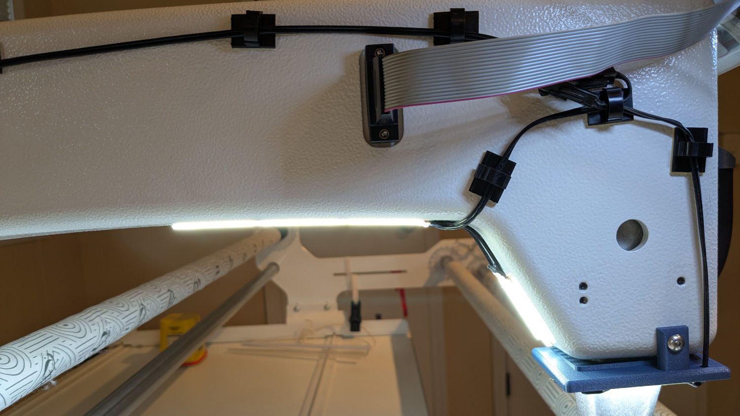
    Fortunately, the wider bracket doesn’t stick out too far beyond the machine frame and the doubled LED strips create a much smoother light pool:

    HQ Sixteen Nose Ring lights - left front view
    HQ Sixteen Nose Ring lights – left front view

    Yes, the quilt is focused and the LED frame is blurred.

    The larger light-emitting area reduces the shadow under the left rod (supporting the ruler foot) enough to be unobjectionable.

    A 0.2 mm layer thickness transforms the smooth ramp into stair steps:

    HQ Sixteen Nose Ring Lights - PrusaSlicer
    HQ Sixteen Nose Ring Lights – PrusaSlicer

    They’re inconspicuous after the bracket is installed.

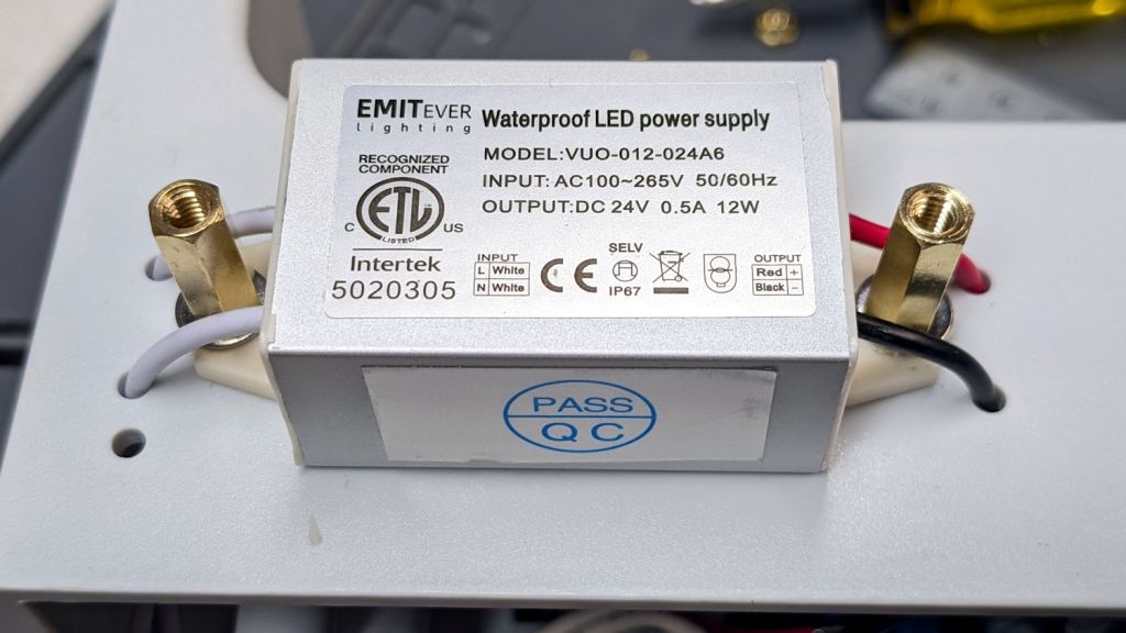
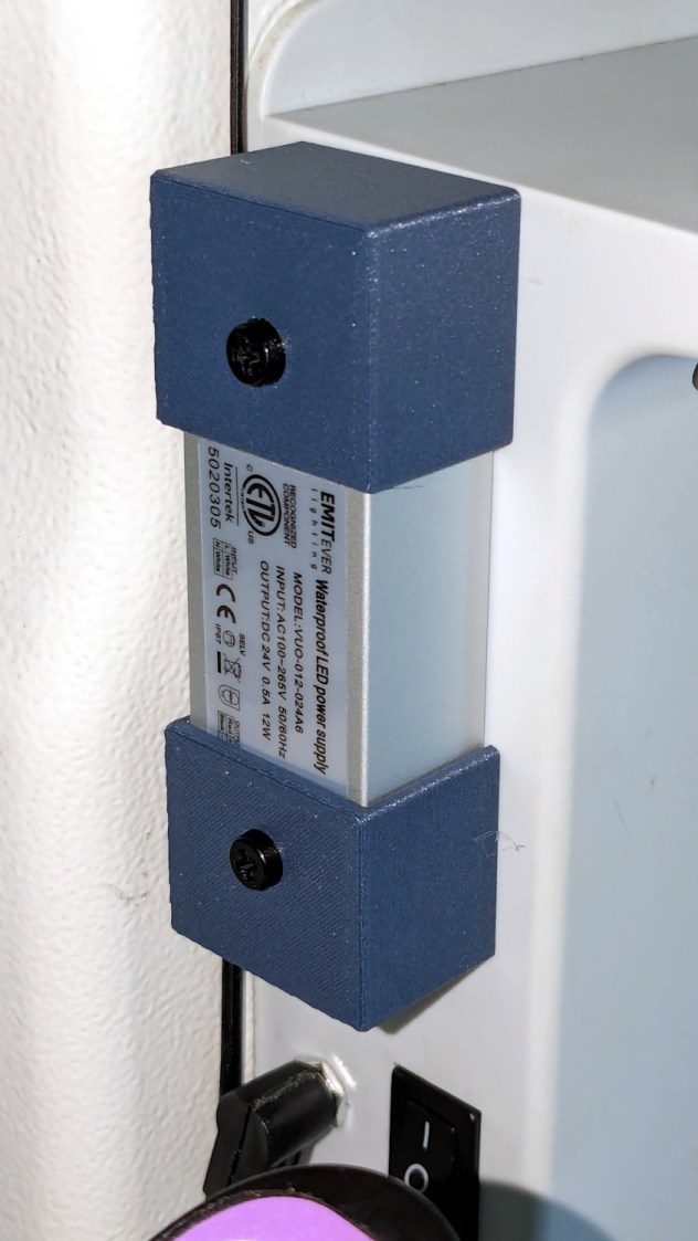
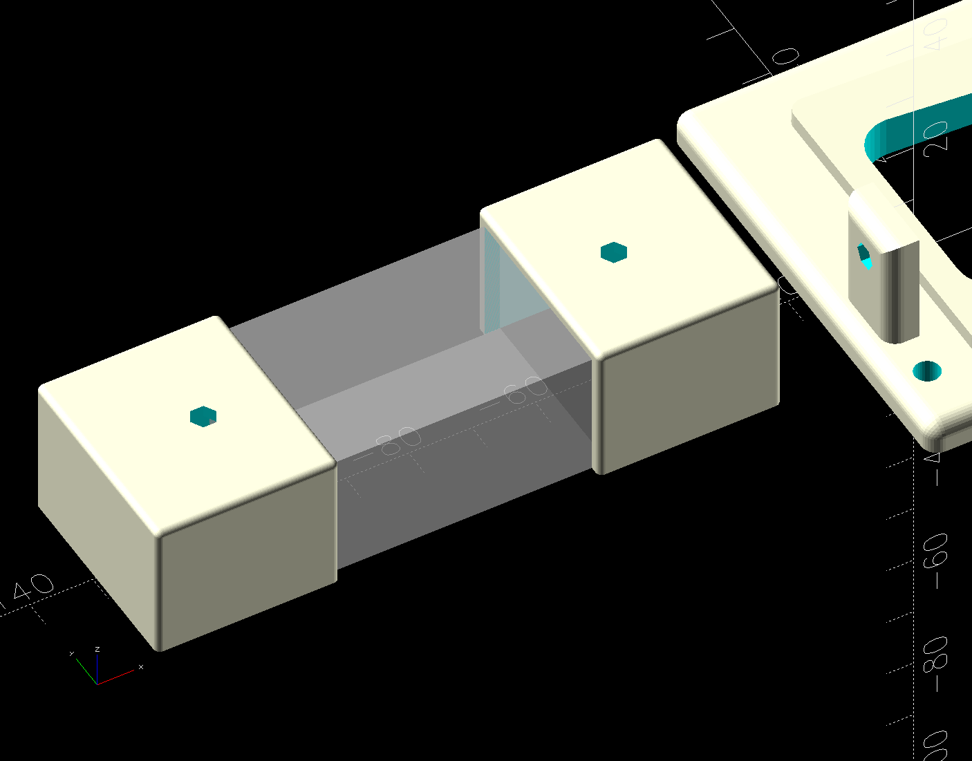
    The Chin Light ran on 12 V and these strips require 24 V, so the OpenSCAD code creates a pair of endcaps for the new supply, which is of course completely different than the old supply. Setting that up must await quilt completion.

    The OpenSCAD source code as a GitHub Gist:

    // HQ Sixteen Nose Ring Lights
    // Ed Nisley – KE4ZNU
    // 2025-05-23
    include <BOSL2/std.scad>
    Layout = "Show"; // [Show,Build,NosePlan,PowerCap]
    // Number of side-by-side LED strips
    Strips = 2;
    /* [Hidden] */
    HoleWindage = 0.2;
    Protrusion = 0.1;
    NumSides = 3*3*4;
    $fn=NumSides;
    ID = 0;
    OD = 1;
    LENGTH = 2;
    Gap = 5.0;
    WallThick = 5.0; // default thickness for things
    NoseRadius = 6.0; // corner roundoff
    NoseOA = [44.0,36.5]; // overall nose size
    NoseAngles = [87,87]; // front & rear inward angles wrt left side
    NoseCenters = [ // centers of circles defining the nose corners
    [NoseRadius, NoseOA.y/2 – NoseRadius],
    [NoseRadius,-(NoseOA.y/2 – NoseRadius)],
    [NoseOA.x – NoseRadius, NoseOA.y/2 – NoseRadius – (NoseOA.x – 2*NoseRadius)*tan(90 – NoseAngles[0])],
    [NoseOA.x – NoseRadius,-(NoseOA.y/2 – NoseRadius – (NoseOA.x – 2*NoseRadius)*tan(90 – NoseAngles[1]))],
    ];
    LEDMargin = 1.0;
    LEDStrip = [41.5 + LEDMargin,8.0 + LEDMargin,1.8 + 0.2]; // 24 V COB LED strip unit + windage
    LEDBaseOA = [LEDStrip.x + Strips*LEDStrip.y,NoseOA.y + 2*Strips*LEDStrip.y,WallThick]; // LED mount
    DraftAngle = 3.0; // angle of frame wrt horizontal at right end of nose
    DraftWedge = [NoseOA.x,NoseOA.y + 2*LEDStrip.y,NoseOA.x*tan(DraftAngle)];
    HoleOffset = [-10.0,5.5,DraftWedge.z + 10.0]; // from left front corner of nose
    HolePosition = HoleOffset + [0,-NoseOA.y/2,WallThick]; // absolute coordinates from origin
    Screw = [4.0 + HoleWindage,9.0,2.0]; // LENGTH=button head
    Bracket = [WallThick,Screw[OD] + 4.0,HoleOffset.z + Screw[OD/2] + 2.0 + WallThick];
    Supply = [46.0,30.0,21.0]; // 24 VDC power supply
    SupplyScrewOffset = 5.0; // … M4 screw hole from end of supply case
    CapWall = 3.0;
    CapRadius = CapWall – 1.0;
    CapInset = 1.0;
    CapOA = [20.0,Supply.y + 2*CapWall,Supply.z + CapWall]; // x & y to cover existing holes
    //———-
    // Define Shapes
    //—– 2D outline of nose piece just under frame casting
    module NosePlan() {
    hull()
    for (p = NoseCenters)
    translate(p) circle(r=NoseRadius);
    }
    //—– LED mounting plate
    module Mount() {
    union() {
    difference() {
    union() {
    right(LEDBaseOA.x/2 – Strips*LEDStrip.y)
    cuboid(LEDBaseOA,rounding=WallThick/2,except=BOTTOM,anchor=BOTTOM);
    up(LEDBaseOA.z) left(-HoleOffset.x/2)
    yrot(DraftAngle)
    cuboid(DraftWedge,rounding=WallThick/2,edges="Z",anchor=LEFT+BOTTOM);
    }
    down(Protrusion)
    linear_extrude(LEDBaseOA.z + DraftWedge.z + Protrusion)
    NosePlan();
    if (Strips > 1)
    translate([HolePosition.x – Bracket.x/2,HolePosition.y – Bracket.y,-Protrusion])
    cyl(LEDBaseOA.z + 2*Protrusion,d=4.0,anchor=BOTTOM);
    }
    difference() {
    union() {
    translate([HolePosition.x,HolePosition.y,(Bracket.x/2)*sin(DraftAngle)])
    left(Bracket.x)
    cuboid(Bracket,rounding=WallThick/2,edges=LEFT,anchor=BOTTOM+LEFT);
    translate([HolePosition.x – Bracket.x/2,HolePosition.y,0]) // rounding filler
    cuboid([LEDStrip.y,Bracket.y,WallThick],anchor=BOTTOM+LEFT);
    }
    translate(HolePosition)
    xrot(180/6) xcyl(l=NoseOA.x,d=Screw[ID],$fn=6);
    }
    }
    }
    //—– Endcap for power supply
    module EndCap() {
    difference() {
    cuboid(CapOA,rounding=CapRadius,except=BOTTOM,anchor=LEFT+BOTTOM);
    right(CapOA.x – CapWall) down(Protrusion)
    cuboid(Supply + [0,0,Protrusion],anchor=RIGHT+BOTTOM);
    right(CapInset + SupplyScrewOffset)
    zcyl(l=2*CapOA.z,d=Screw[ID],$fn=6,anchor=BOTTOM);
    }
    }
    //———-
    // Build things
    if (Layout == "NosePlan") {
    NosePlan();
    }
    if (Layout == "PowerCap") {
    EndCap();
    }
    if (Layout == "Show") {
    Mount();
    ctr = 80;
    ofs = Supply.x/2 – CapInset;
    left(ctr – ofs)
    EndCap();
    left(ctr + ofs)
    xflip()
    EndCap();
    color("Silver",0.6)
    left (ctr)
    cuboid(Supply,anchor=BOTTOM);
    }
    if (Layout == "Build") {
    Mount();
    back((LEDBaseOA.y + CapOA.y)/2 + Gap) right(Gap) up(CapOA.z) zflip()
    EndCap();
    back((LEDBaseOA.y + CapOA.y)/2 + Gap) left(Gap) zrot(180) up(CapOA.z) zflip()
    EndCap();
    }

  • HQ Sixteen: Chin Light Failure

    HQ Sixteen: Chin Light Failure

    The COB LED module I stuck under the HQ Sixteen’s chin worked well at first:

    HQ Sixteen Chin Light - results
    HQ Sixteen Chin Light – results

    Last month it began to flicker and I eventually caught it in the act:

    HQ Sixteen Chin Light - first failure
    HQ Sixteen Chin Light – first failure

    That’s taken with the phone’s selfie camera from the quilt’s viewpoint, which is much too close for the camera’s focus, but you get the general idea.

    Pulling it off, putting it on the bench, applying 12 V, and letting it heat up produced this:

    HQ Sixteen Chin Light - hot failure
    HQ Sixteen Chin Light – hot failure

    That’s with the voltage backed off to 8 V to avoid burning out the exposure.

    Letting it cool a bit:

    HQ Sixteen Chin Light - cool failure
    HQ Sixteen Chin Light – cool failure

    You may recall I stuck the aluminum backing plate to the HQ Sixteen’s case aluminum body with some heatsink tape and the thing ran just warm to the touch, so I suspect the initial failure had little-or-nothing to do with overheating and a lot to do with buying stuff from eBay.

    That suspicion is supported by having two more of those in the drawer with their failed chips circled.

    So a better design is in order …

  • Lamp Socket Adapter: Weld Failure

    Lamp Socket Adapter: Weld Failure

    The basement came with several LED bulbs screwed into old-school ceramic sockets with pull-chain switches. This adapter had an LED bulb in its socket and another LED fixture plugged into an outlet:

    Lamp socket adapter - failed weld
    Lamp socket adapter – failed weld

    The fixture began flickering some days ago, which I attributed to a problem with its power supply. When both the bulb and the fixture went dark, I had enough of a clue to locate the real cause.

    The scorched plastic near the discolored weld nugget on the threaded shell suggests something ran overly hot in there for a while.

    Peeling the aluminum shell off reveals the problem:

    Lamp socket adapter - detail
    Lamp socket adapter – detail

    Looks to me like the weld started out weak and gradually fell apart as the socket heated / cooled in use, with increasing resistance producing more heat every time.

    The LED lamp + fixture added up to 100 W, so about 1 A is all it takes.

  • Whirlpool Clothes Dryer Thermal Switches

    Whirlpool Clothes Dryer Thermal Switches

    The venerable (circa 1993) Whirlpool clothes dryer (LER443AQ0) that Came With The House™ failed in action: the drum occasionally stopped turning (and, fortunately, heating) while the control timer continued ticking along. The symptoms suggested one of the many thermal switches / thermostats / fuses was bad, but because the problem was intermittent, the only practical alternative was replacing all the things.

    Which, it turns out, costs about ten bucks from the usual source. I remain unconvinced paying an order of magnitude more for what look to be identical parts will, in fact, bring either different parts or higher quality.

    The wiring diagram, which I consulted only after the fact, shows it was most likely the “Not Resettable” Thermal Fuse in series with the drum motor, because the other contestants are in series with the heater and the Operating Thermostat would trip when the blower stopped blowing:

    Whirlpool dryer - wiring diagram - detail
    Whirlpool dryer – wiring diagram – detail

    The fact that the Thermal Fuse should not “reset” after it trips seems worrisome, but failures are like that.

    All those parts are accessible only through the rear cover, but you should definitely vacuum out as much fuzz as possible before popping the cover (with vacuum in hand):

    Whirlpool dryer - heater duct top
    Whirlpool dryer – heater duct top

    Of course, all the old parts show fine continuity, because intermittent:

    Whirlpool dryer - thermal switches
    Whirlpool dryer – thermal switches

    With the new parts in place, the dryer has chugged through half a dozen loads without incident: so all’s well that ends well.

  • Auto Side Marker Bulb: FAIL

    Auto Side Marker Bulb: FAIL

    Six years ago I replaced the W5W incandescent front side marker bulbs in our 2015 Subaru Forester with amber LED bulbs:

    Side Marker bulbs - failed adhesive
    Side Marker bulbs – failed adhesive

    The adhesive holding the LED PCB to the aluminum “heatsink” has fossilized and the strip on the right is peeling off (with the left one not far behind), which likely accounted for its loss of light output and flickering.

    Tearing it apart reveals the LED layout and what looks like a bridge rectifier or a big resistor (to fool the CAN bus?) on a tiny PCB jammed inside the shell:

    Side Marker bulbs - rectifier
    Side Marker bulbs – rectifier

    The other side of the PCB could be a buck converter:

    Side Marker bulbs - buck converter
    Side Marker bulbs – buck converter

    In round numbers, we’ve driven 18000 miles at an average of maybe 40 mph over those years; call it 450 hours. However, the side marker lights aren’t on unless the headlights are on; we do very little night driving, which means those LED bulbs are the usual crap.

    I replaced both front bulbs with a different design sporting two LED chips and we’ll see how long those last.

  • Anker LC-40 Flashlight Switch Repair

    Anker LC-40 Flashlight Switch Repair

    The switch on the Anker LC-40 flashlight serving as a running light on my Tour Easy became slightly intermittent before I replaced it with a 1 W amber LED, but it was still good enough to become the troubleshooting flashlight in the tray next to the Prusa Mk 4 printer. Eventually, of course, it failed completely and Something Had To Be Done.

    Although I knew an exact replacement switch had to be available from the usual sources, I could not come up with a set of keywords capable of pulling them out of the chaff.

    That was not a problem, because the assortment of SMD switches I used to replace the handlebar control caps on Mary’s Handi-Quilter HQ Sixteen contained push-on / push-off switches that were almost the right size:

    Anker LC-40 Flashlight - switches and caps
    Anker LC-40 Flashlight – switches and caps

    Having recently convinced the MakerGear M2 3D printer to use TPU filament, all I had to do was produce a suitable cap to fit over the new switch in the flashlight’s tail:

    Anker LC-40 Flashlight Button - TPU PrusaSlicer
    Anker LC-40 Flashlight Button – TPU PrusaSlicer

    Which turned into a multi-dimensional search over cap geometry, TPU extrusion speeds & feeds, and various impossible-to-directly-measure sizes:

    Anker LC-40 Flashlight - TPU cap iterations
    Anker LC-40 Flashlight – TPU cap iterations

    The squarish block over on the left is PrusaSlicer’s version of a support structure wrapped around the first cap version; if human lives depended on it, I could surely extract the cap, but it would take a while.

    The remaining debris samples occured while discovering:

    • An extruder temperature of 230 °C, not 250 °C, works well
    • A conical shape of the lip around the open end to eliminate the support structure
    • TPU doesn’t bridge well, so the closed end must be down
    • Length of the central pillar to barely touch the switch stem when released
    • Cap length and wall thickness so the TPU shell can collapse enough to actuate and release the switch stem
    • And so on and so on and scooby dooby dooby

    Eventually I came up with a suitable combination:

    Anker LC-40 Flashlight - switch caps
    Anker LC-40 Flashlight – switch caps

    Because I expected this would be an easy job, I used snap ring pliers to unscrew and rescrew the threaded retaining ring holding the switch PCB in place. Because the pliers didn’t have a stable grip on the ring, the threads eventually became just a bit goobered.

    This was not a problem, because I have a(nother) 3D printer:

    Anker LC-40 Flashlight Retainer - show view
    Anker LC-40 Flashlight Retainer – show view

    The gray thing on the right is a simple pin wrench fitting both the original and the replacement retaining rings, so I can orient the rings properly while unscrewing & rescrewing:

    Anker LC-40 Flashlight - pin wrench in place
    Anker LC-40 Flashlight – pin wrench in place

    The threads have a 0.75 mm pitch and, while it’s possible to print screw threads, even a tedious 0.1 mm layer height would define each turn of the thread with only 7-½ layers.

    This was not a problem, because I have a mini-lathe:

    Anker LC-40 Flashlight - thread cutting
    Anker LC-40 Flashlight – thread cutting

    The yellow & green things on the left of those solid models are the fixture holding a retaining ring for threading and the washer applying pressure to keep the ring in place:

    Anker LC-40 Flashlight - lathe fixture - detail
    Anker LC-40 Flashlight – lathe fixture – detail

    The alert reader will note that washer lacks holes for the alignment pins I added after seeing the washer sit not quite concentric on the fixture. I could call it continuous product improvement, although I doubt I’ll print another one.

    Setting up the lathe involved finding the proper set of change gears, including the vital 42-50 stacked gear I made a while ago to print metric threads on a hard-inch lathe:

    Anker LC-40 Flashlight - lathe change gear train
    Anker LC-40 Flashlight – lathe change gear train

    Although you’re supposed to measure the thread spacing on a skim pass, I find it’s easier to just measure the carriage movement for one spindle rotation:

    Anker LC-40 Flashlight - lathe gear check
    Anker LC-40 Flashlight – lathe gear check

    A few passes produced a fine retaining ring:

    Anker LC-40 Flashlight - pin wrench - detail
    Anker LC-40 Flashlight – OEM vs lathe-cut threads

    Sporting much nicer looking threads than the goobered original:

    Anker LC-40 Flashlight - OEM vs lathe-cut threads
    Anker LC-40 Flashlight – OEM vs lathe-cut threads

    The original switch had a stabilizing ring around the body to prevent it from wobbling under the original rubber cap.

    This was not a problem, because I have a laser cutter:

    Anker LC-40 Flashlight - new switch in stabilizer
    Anker LC-40 Flashlight – new switch in stabilizer

    Those came from a scrap of fluorescent acrylic.

    The wave washer behind the acrylic stabilizer improves the contact between the PCB trace around the rim and the flashlight tailcap, with the current passing through the body to the “light engine” up front. The retaining ring provides enough pressure to compress the wave washer, which is why it’s so easily goobered without a close-fitting pin wrench.

    With everything assembled in reverse order, the flashlight worked pretty much as it did back when it was new:

    Anker LC-40 Flashlight - TPU cap installed
    Anker LC-40 Flashlight – TPU cap installed

    However, after describing this during a recent SquidWrench meeting, I discovered that adding “latching” to my keywords surfaced a bodacious assortment of flashlight switches, so (a few days later) I removed the not-quite-right switch and replaced it with an identical twin of the OEM switch requiring just a little lead forming to fit the PCB.

    Even better, using the 3D printed pin wrench to screw the original retaining ring into the flashlight’s aluminum threads a few times re-formed (unrelated to recent electrolytic capacitor reforming) its goobered threads well enough to fit and work perfectly again.

    So I have:

    • … reassembled the flashlight with more-or-less original components
    • … a repair tool kit ready when another LC-40 fails
    • … re-learned the lesson that any time spent making a fixture or a special tool is not deducted from one’s allotment

    And I loves me a happy ending or two!

    The OpenSCAD source code as a GitHub Gist:

    // Anker LC-40 flashlight switch retainer
    // Ed Nisley – KE4ZNU
    // 2025-05-05
    include <BOSL2/std.scad>
    Layout = "Show"; // [Show,Build,Retainer,Fixture,Washer,Wrench]
    Gap = 5; // [0:10]
    /* [Hidden] */
    HoleWindage = 0.2;
    Protrusion = 0.1;
    NumSides = 3*3*4;
    ID = 0;
    OD = 1;
    LENGTH = 2;
    $fn=3*3*4;
    Plate = [16.8,20.0,3.0]; // retainer plate, OD allows for lathe threading
    PlateRecessDepth = 1.6;
    PlateInnerThick = Plate[LENGTH] – PlateRecessDepth;
    ClearID = 11.0;
    PinOD = 3.0;
    PinOC = 12.0;
    WrenchLength = 25.0; // handle on wrench
    JawLength = 22.0; // lathe jaw
    ThreaderOverrun = 10.0; // stick-out for threading tool clearance
    ThreadAllowance = 2*1.0; // clearance for thread depth
    //———-
    // Define Shapes
    module Retainer() {
    difference() {
    tube(Plate[LENGTH],od=Plate[OD],id=ClearID,anchor=BOTTOM);
    up(Plate[LENGTH] + Protrusion)
    cyl(PlateRecessDepth + Protrusion,d=Plate[ID],anchor=TOP);
    down(Protrusion)
    hull()
    for (i = [-1,1])
    right(i*PinOC/2) down(Protrusion)
    cyl(Plate[LENGTH] + Protrusion,d=PinOD,anchor=BOTTOM);
    }
    }
    module Fixture() {
    difference() {
    regular_prism(6,h=JawLength,d=1.2*Plate[OD],anchor=BOTTOM) position(TOP) {
    cyl(PlateRecessDepth + ThreaderOverrun,d=Plate[ID],anchor=BOTTOM);
    cyl(Plate[LENGTH] + ThreaderOverrun,d=ClearID,anchor=BOTTOM);
    // hull()
    for (i = [-1,1])
    right(i*PinOC/2)
    cyl(Plate[LENGTH] + ThreaderOverrun + Plate[LENGTH]/2,d=PinOD,anchor=BOTTOM);
    cyl(ThreaderOverrun,d=Plate[OD] – ThreadAllowance,anchor=BOTTOM);
    }
    up(JawLength + ThreaderOverrun + Plate[LENGTH] + Protrusion) // M4 burly insert
    cyl(10.0 + 5,d=5.5,anchor=TOP);
    }
    }
    module Washer() {
    difference() {
    tube(Plate[LENGTH],od=Plate[OD] – ThreadAllowance,id=4.5,anchor=BOTTOM);
    down(Protrusion)
    for (i = [-1,1])
    right(i*PinOC/2)
    cyl(2*Plate[LENGTH],d=PinOD,anchor=BOTTOM);
    }
    }
    module Wrench() {
    difference() {
    union() {
    cyl(WrenchLength,d=Plate[ID],anchor=BOTTOM);
    for (i = [-1,1])
    right(i*PinOC/2)
    cyl(WrenchLength + Plate[LENGTH],d=PinOD,anchor=BOTTOM);
    }
    down(Protrusion)
    cyl(2*WrenchLength,d=ClearID – 2.0,anchor=BOTTOM);
    }
    }
    //———-
    // Build things
    if (Layout == "Retainer")
    Retainer();
    if (Layout == "Fixture")
    Fixture();
    if (Layout == "Washer")
    Washer();
    if (Layout == "Wrench")
    Wrench();
    if (Layout == "Show") {
    color("Gold")
    Fixture();
    up(JawLength + ThreaderOverrun + Gap)
    zflip(z=Plate[LENGTH]/2)
    Retainer();
    color("Green")
    up(JawLength + ThreaderOverrun + Plate[LENGTH] + 2*Gap)
    Washer();
    right(40) {
    zflip(z=Plate[LENGTH]/2)
    Retainer();
    color("Silver")
    up(Plate[LENGTH] + Gap)
    zflip(z=WrenchLength/2)
    Wrench();
    }
    }
    if (Layout == "Build") {
    Fixture();
    right(1.5*Plate[OD]) {
    Retainer();
    fwd(1.5*Plate[OD])
    Retainer();
    }
    left(1.5*Plate[OD])
    Washer();
    fwd(1.5*Plate[OD])
    Wrench();
    }