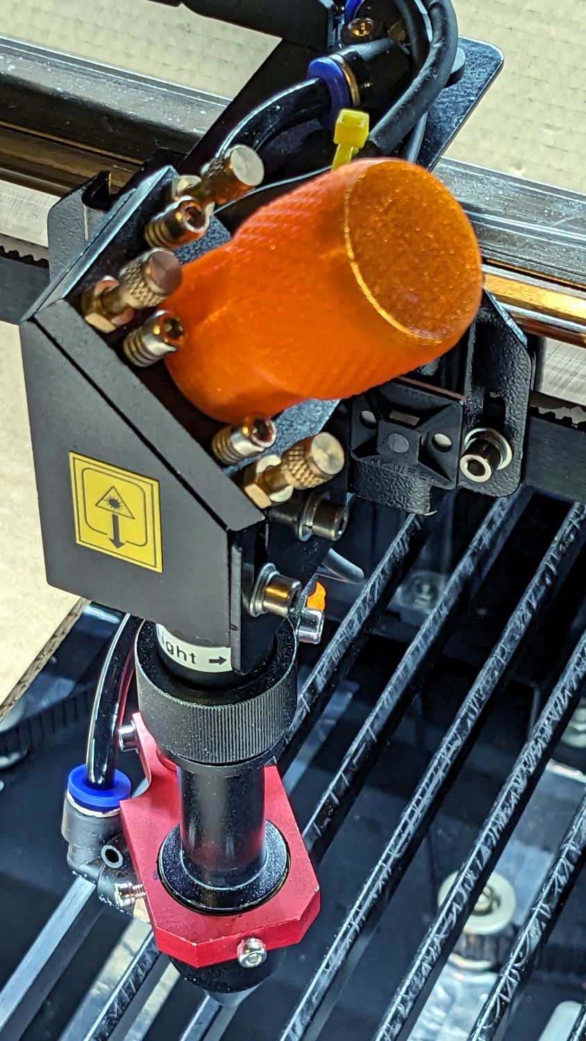
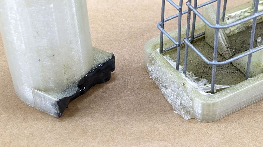
After struggling with pin pliers again, I finally made a pin wrench for the laser cutter’s mirror retaining rings:

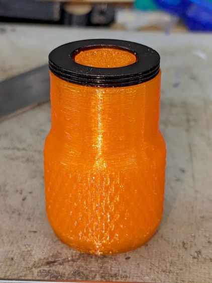
The odd grayish tint toward the flat end of the knob comes from residual black filament in the hot end after switching to retina-burn orange PETG.
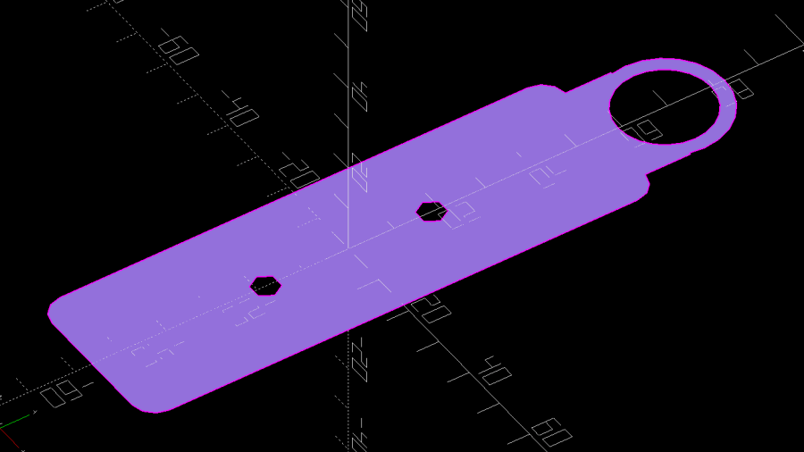
The solid model looks about like you’d expect:

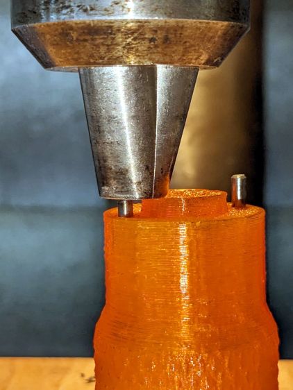
The pins are snippets of 3/32 inch = 2.4 mm steel rod with ground-round ends to fit the 2.5 mm pin sockets in the retaining ring.
They’re rammed into place with a drill press to keep them aligned with the holes:

Pressed flush with the central boss that aligns the wrench with the ring:
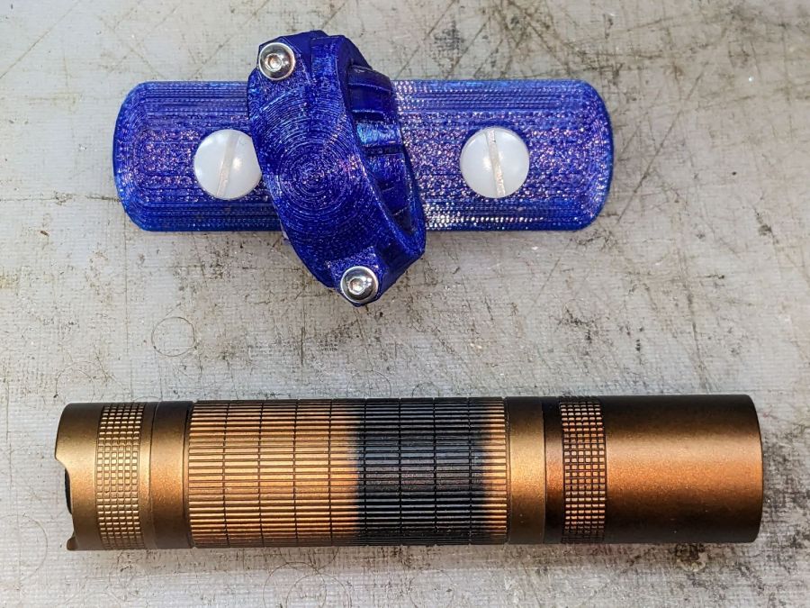
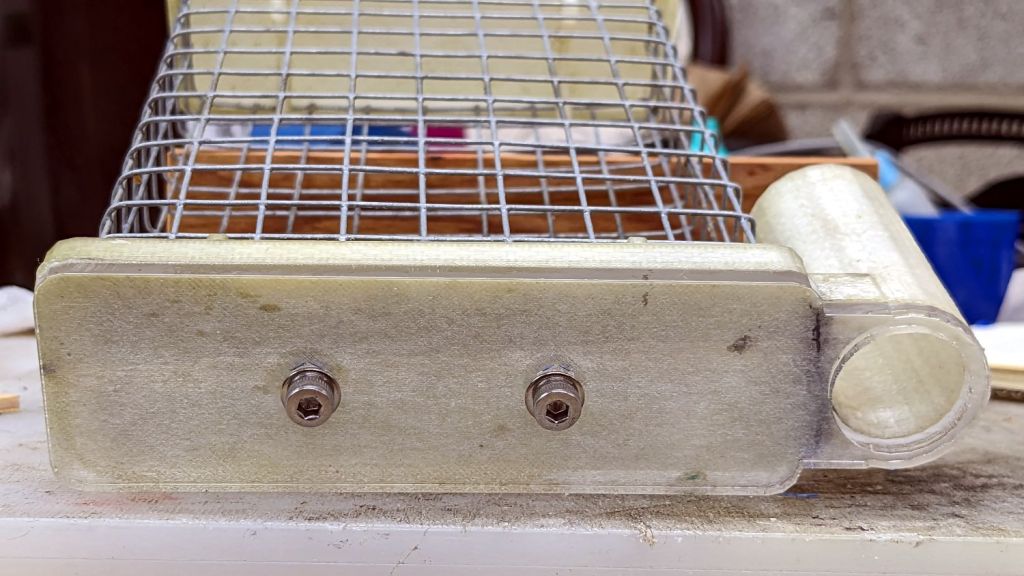
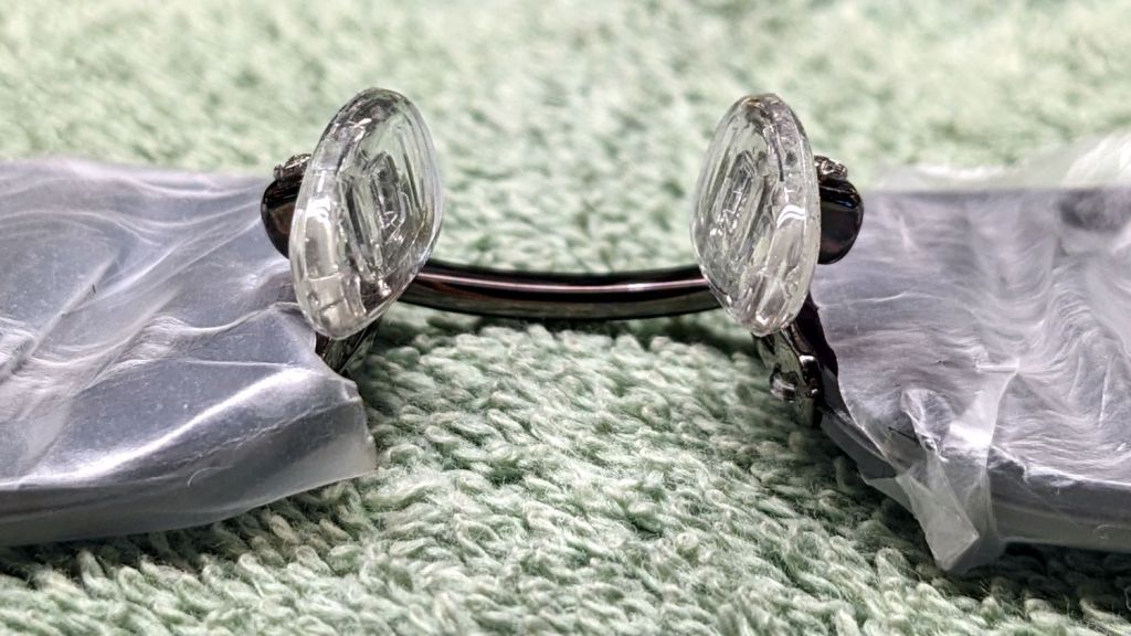
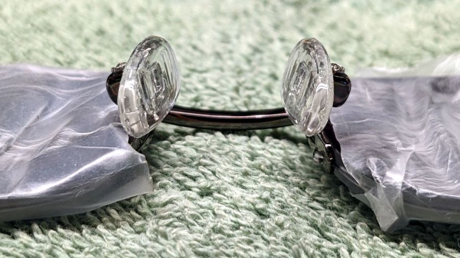
Then put the ring on the bench, set the wrench atop the ring with the pins in the sockets, and press firmly to seat the pins to the proper depth. The end results should look like this:
The next time I clean the mirrors, there will be less muttering.
The OpenSCAD source code as a GitHub Gist:
| // OMTech laser cutter mirror pin wrench | |
| // Ed Nisley – KE4ZNU – August 2023 | |
| // From https://www.thingiverse.com/thing:4146258 | |
| use <knurledFinishLib_v2_1.scad> | |
| /* [Hidden] */ | |
| ThreadThick = 0.20; | |
| ThreadWidth = 0.40; | |
| HoleWindage = 0.2; // extra clearance | |
| Protrusion = 0.1; // make holes end cleanly | |
| inch = 25.4; | |
| //———————- | |
| // Dimensions | |
| /* [Knob] */ | |
| PinDia = 2.4; // pin diameter | |
| PinOC = 20.5; // … on-center spacing | |
| PinDepth = 10.0; // … hole depth | |
| LocDia = 14.5; // central stud | |
| LocLength = 3.0; | |
| ShaftDia = 26.0; // un-knurled section diameter | |
| ShaftLength = 15.0; // … length | |
| KnurlDia = 30.0; // diameter at midline of knurl diamonds | |
| KnurlLen = 20.0; // … length of knurled section | |
| /* [Hidden] */ | |
| KnurlDPNom = 32; // Nominal diametral pitch = (# diamonds) / (OD inches) | |
| DiamondDepth = 0.5; // … depth of diamonds | |
| DiamondAspect = 2; // length to width ratio | |
| KnurlID = KnurlDia – DiamondDepth; // dia at bottom of knurl | |
| NumDiamonds = ceil(KnurlDPNom * KnurlID / inch); | |
| echo(str("Num diamonds: ",NumDiamonds)); | |
| NumSides = 4*NumDiamonds; // 4 facets per diamond | |
| KnurlDP = NumDiamonds / (KnurlID / inch); // actual DP | |
| echo(str("DP Nom: ",KnurlDPNom," actual: ",KnurlDP)); | |
| DiamondWidth = (KnurlID * PI) / NumDiamonds; | |
| DiamondLenNom = DiamondAspect * DiamondWidth; // nominal diamond length | |
| DiamondLength = KnurlLen / round(KnurlLen/DiamondLenNom); // … actual | |
| TaperLength = 0.75*DiamondLength; | |
| KnobOAL = ShaftLength + KnurlLen + 2*TaperLength; | |
| //———————- | |
| // Useful routines | |
| module PolyCyl(Dia,Height,ForceSides=0) { // based on nophead's polyholes | |
| Sides = (ForceSides != 0) ? ForceSides : (ceil(Dia) + 2); | |
| FixDia = Dia / cos(180/Sides); | |
| cylinder(r=(FixDia + HoleWindage)/2, | |
| h=Height, | |
| $fn=Sides); | |
| } | |
| //- Build it | |
| difference() { | |
| union() { | |
| render(convexity=10) | |
| translate([0,0,TaperLength]) | |
| knurl(k_cyl_hg=KnurlLen, | |
| k_cyl_od=KnurlDia, | |
| knurl_wd=DiamondWidth, | |
| knurl_hg=DiamondLength, | |
| knurl_dp=DiamondDepth, | |
| e_smooth=DiamondLength/2); | |
| color("Orange") | |
| cylinder(r1=ShaftDia/2, | |
| r2=(KnurlDia – DiamondDepth)/2, | |
| h=(TaperLength + Protrusion), | |
| $fn=NumSides); | |
| color("Orange") | |
| translate([0,0,(TaperLength + KnurlLen – Protrusion)]) | |
| cylinder(r2=ShaftDia/2, | |
| r1=(KnurlDia – DiamondDepth)/2, | |
| h=(TaperLength + Protrusion), | |
| $fn=NumSides); | |
| color("Moccasin") | |
| translate([0,0,(2*TaperLength + KnurlLen – Protrusion)]) | |
| cylinder(r=ShaftDia/2,h=(ShaftLength + Protrusion),$fn=NumSides); | |
| color("Brown") | |
| translate([0,0,KnobOAL – Protrusion]) | |
| cylinder(r=LocDia/2,h=(LocLength + Protrusion),$fn=NumSides); | |
| } | |
| for (i=[-1,1]) | |
| translate([i*PinOC/2,0,KnobOAL – PinDepth]) | |
| rotate(180/6) | |
| PolyCyl(PinDia,PinDepth + Protrusion,6); | |
| } |
It descends from a long line of similar things dating back to the OG Sherline Speed Wrenches.


