Ed Nisley's Blog: Shop notes, electronics, firmware, machinery, 3D printing, laser cuttery, and curiosities. Contents: 100% human thinking, 0% AI slop.
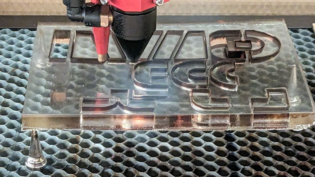
It’s the sheet of 3/8 inch = 9 mm vintage acrylic that Came With The House™ and what you see is the relatively unwarped result of several months of pressure. The wood sheet in front puts the left edge mostly flat on the platform, with the steel disk weighting the rear end down; the front end sticks out through the laser’s pass-through door.
The general idea was to cut a rectangle that would be flat enough for the shapes I actually needed:
Blockface grip cutting
They’re grips for a set of Blockface printing shapes. The alert reader will note the rectangle sits atop three spikes, not the usual four; it was flat enough for the purpose, not actually flat.
The OMTech laser claims to be 60 W, but has an over-amped 50 W tube that’s barely adequate for the task. The cuts required two passes:
5 mm/s @ 90% cuts almost all the way through
10 mm/s @ 90% clears the cut enough to have some shapes drop out and the others be easily pushed through
Cranking the tube current that high isn’t recommended practice, either, but sometimes ya gotta do what ya gotta do.
To my utter astonishment, the rubber cuts did not smell like a tire fire and the neighbors did not rise up in arms.
I cut several sets of grips / foam / rubber and sent them off for final assembly. The recipient seems delighted with the results and has been hand-printing up a storm.
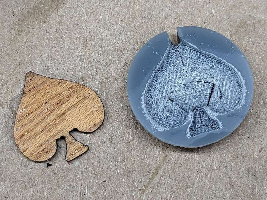
Trying a sequence of offset and raster filling produced a credible 0.5 mm deep inlay pocket in a chunk of acrylic:
Earring samples – veneer spade recess
The odd pattern inside the pocket comes from the offset fill:
Veneer spade pocket – LightBurn preview
Combining the two fill patterns produces a smoother bottom in the pocket, but it’s a good thing nobody will ever see it from the back side, because the offset fill concentrations chew through the entire 3mm sheet.
A spade-shaped adhesive sheet bonded the veneer into the pocket, after which I sanded the surface flat with 200 grit sandpaper and hit it with some polyurethane sealer. Next time I’ll knock the finished surface flat with 400 grit paper.
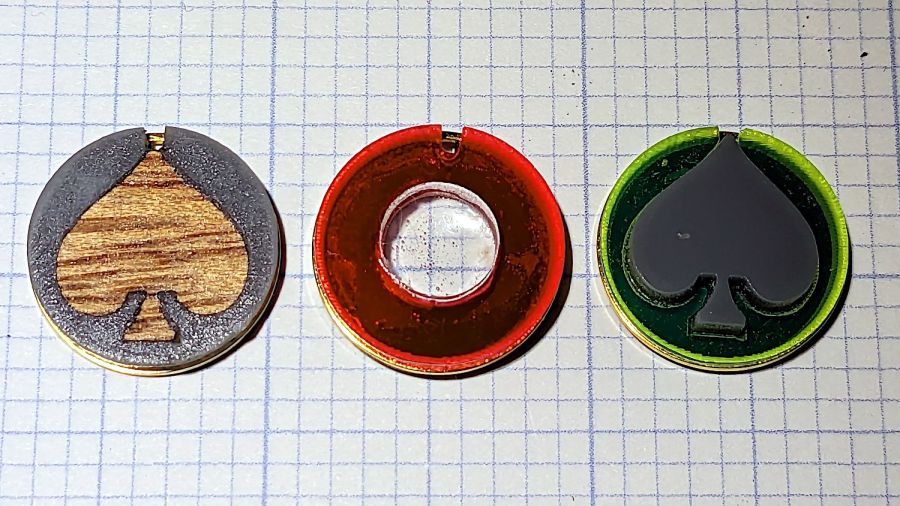
The gray acrylic disk has a rebate around its rear rim for the “gold” ring, with the adhesive disk gluing the black disk to the front:
Earring samples – veneer spade parts
Which looks like this when it’s stuck together:
Earring samples – veneer spade side view
I don’t like the raggedy surface of the rebate above the ring, although it’s not too awful in person.
Having gotten reasonable results with the acrylic pocket, I cut an acrylic spade and stuck it in place with another bit of adhesive sheet, leaving it standing proud of the surface:
Earring samples – veneer spade acrylic
The red earring used up one of the hundred slugs left over from the capsule plate; I’m ready for a surge in demand.
The adhesive sheet is workable in disk form, but the spade shape is entirely too fiddly. A dab of acrylic adhesive would likely work just as well and be easier all around.
Nuheara predicts two to three years of battery lifetime for their IQbuds² MAX not-really-hearing-aids and, indeed, after 2-½ years of more-or-less steady use, the right bud developed a bad case of not charging fully and discharging quickly. The batteries are not, of course, customer-replaceable, so one can:
Buy a single bud
Buy a complete new pair + case + accessories
Ask about their repair service
Unsurprisingly, a single bud costs more than half the cost of the full set and the repair service is a complete mystery. Given that the left bud’s battery will likely fail in short order, let’s find out what’s inside.
Your ear sees this side:
Nuheara IQbud – bottom view
The dark oval is a (probably IR) sensor telling the bud when it’s jammed in your ear.
Everybody else sees this side:
Nuheara IQbud – top view
The small slit over on the right and the two holes around the top seem to be for various microphones.
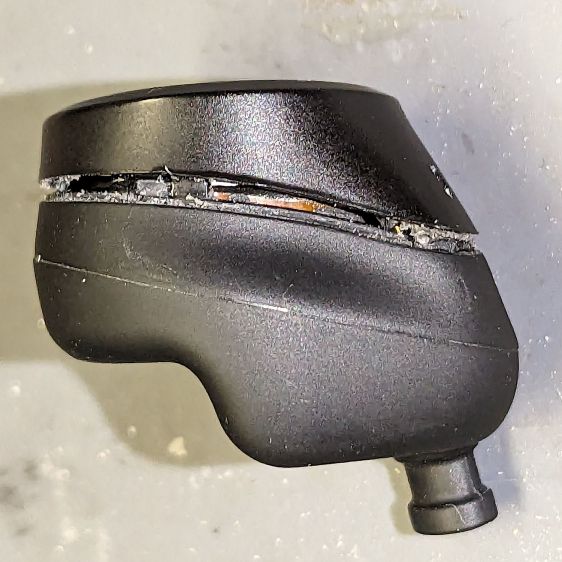
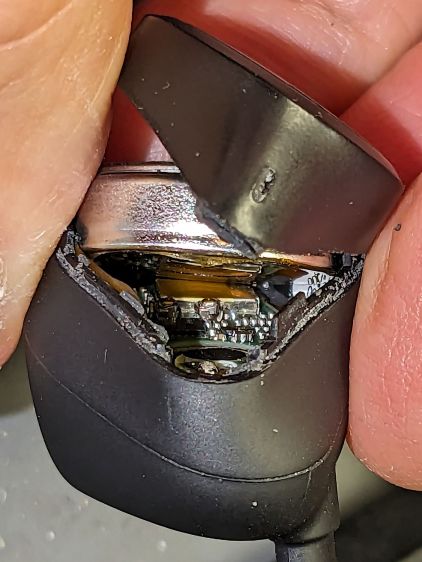
Jamming a plastic razor blade into the junction between the two parts of the case, just under the mic slit, and gently prying around the perimeter eventually forces the adhesive apart:
Nuheara IQbud – case splitting
Do not attempt to yank the two pieces apart, because a ribbon cable joins the lower and upper PCBs:
Nuheara IQbud – ribbon cable
The metallic disk in the lower part is the lithium battery.
Ease the upper part away, being very careful about not tugging on the ribbon cable:
Nuheara IQbud – raising battery
The battery has moved upward, revealing the lower PCB.
Rolling the upper part toward the ribbon cable eventually produces enough space to extract the battery:
Nuheara IQbud – battery freed
Note the orientation:
The rebated end is the negative terminal and faces outward
The wider end is the positive terminal and faces inward
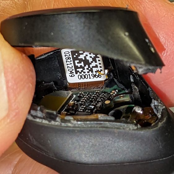
With the battery out, you can admire the PCBs and ribbon cable:
Nuheara IQbud – interior view
What is not obvious from the picture: two pairs of spring-loaded pogo pins contacting the battery. There is no actual battery holder, as it’s just tucked into the structure of the bud, with the perimeter adhesive providing the restraining force for the pogo pins.
The 1654 cells I got came with wire leads welded to the cell and a complete Kapton enclosure; apparently other devices use soldered connections rather than pins. They proudly proclaim their “Varta” heritage, but I have no way to prove they actually came from Germany.
I snipped off the wires, carved a pair of holes through their Kapton for the contact pins, tucked the cell in the bud, pressed the halves together, applied a clamp, then wrapped a strip of Kapton tape around the perimeter:
Nuheara IQbud – reassembled
It seems remarkably easy to wrap the tape over the front microphone, but don’t do that. Conversely, sealing the entire perimeter is the only way to prevent acoustic feedback, so I added a snippet of tape just under the front mic opening.
Do that for the other bud and declare victory.
That is, fer shure, not the most stylin’ repair you’ve ever seen, but I was (for what should be obvious reasons) reluctant to glue the halves together. I expect the tape to peel off / lose traction after a while, but I have plenty of tape at the ready. Worst case, I can glop some adhesive in there and hope for the best.
Because the buds lost power during their adventure, they required a trip through their charging case to wake them up again. After that, they work as well as they did before, with consistently longer run time from both buds.
The Moonlander keyboard has per-key LEDs that I’ve denatured enough that most show a pale gray, with a few others highlighted in orange. A few weeks ago the LEDs on the right-hand thumb cluster and the N key went nuts, cycling through a surprising assortment before settling on bright red; the obvious resets / firmware reflashing / tapping were all unavailing.
ZSA’s tech support recommended taking the thumb cluster apart to check the ribbon cable connecting it to the main keyboard half:
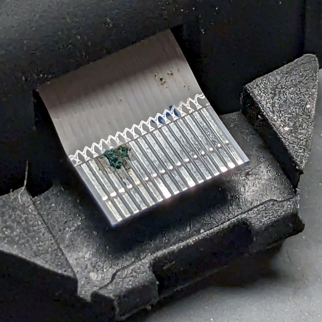
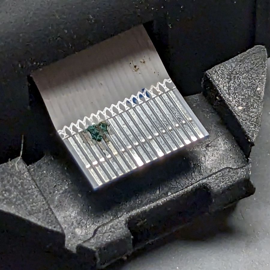
Moonlander thumb cluster – PCB bottom
Come to find out my unclean personal habits lodged a particularly corrosive nugget of board chow on the cable:
Moonlander – corroded ribbon cable
It’s a more-or-less standard 0.5 mm pitch cable, but only 20-ish mm long, much shorter than the cables carried by the usual sources. ZSA sells them for $2 each, plus $25 courier shipping, so I bought three; they arrived in two days from halfway around the planet.
Because I don’t foresee my personal habits changing any time soon, I tucked a Kapton tape snippet in the gap to serve as a gutter:
Moonlander thumb cluster – tape shield installation
That’s with the two hinge screws out and the cluster eased down-and-away from the keyboard enough to get the tape pressed against the keyboard.
With the screws installed and the cluster at its normal most-downward angle, the gutter closes up:
Moonlander thumb cluster – tape shield folded
With the cluster in its normal operating position (for me, anyway), the gutter is nearly invisible:
Moonlander thumb cluster – normal position
For the record, I tucked the remaining ribbon cables inside the left-hand thumb cluster against future need.
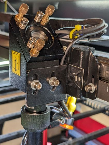
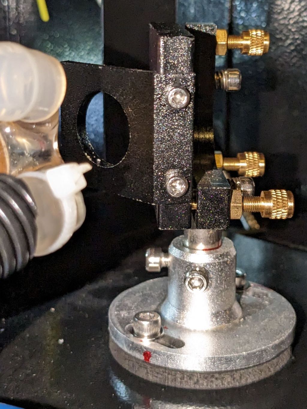
With Mirror 1 and Mirror 2 aligned, the next step is positioning the laser head to put the beamline at the center of both the aperture and Mirror 3 inside:
OMTech CO2 Mirror 3 mount – realigned – Z screws
Raising the laser tube by 5 mm put the head’s Z axis screws in the middle of their slots. This had the additional benefit of letting me rotate the head slightly around the X axis to make it perpendicular with the bed, thus fixing its mysterious from-the-factory misalignment.
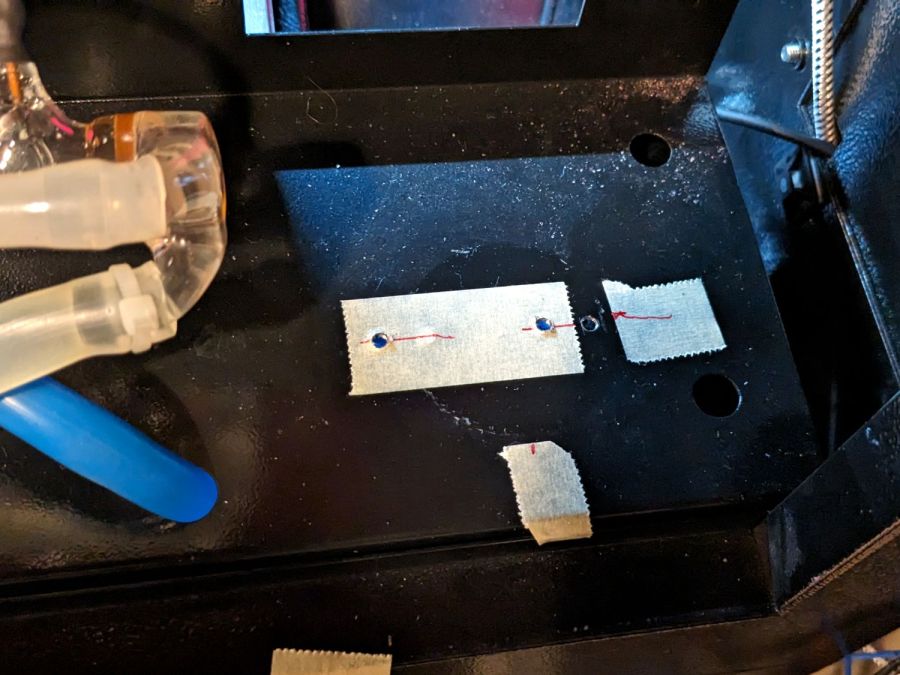
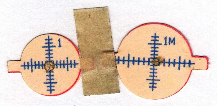
Centering the beamline horizontally required a few iterations of Mirror 2’s position along the Y axis, but eventually produced this result:
Beam Alignment – Mirror 3 detail – 2023-09-16
Those are five manual pulses with the head at the corners and center of the platform. I put the 3M target on the mirror rotated 90° from the proper orientation with the stretched scale aligned vertically and parallel to the slightly oval beam mark.
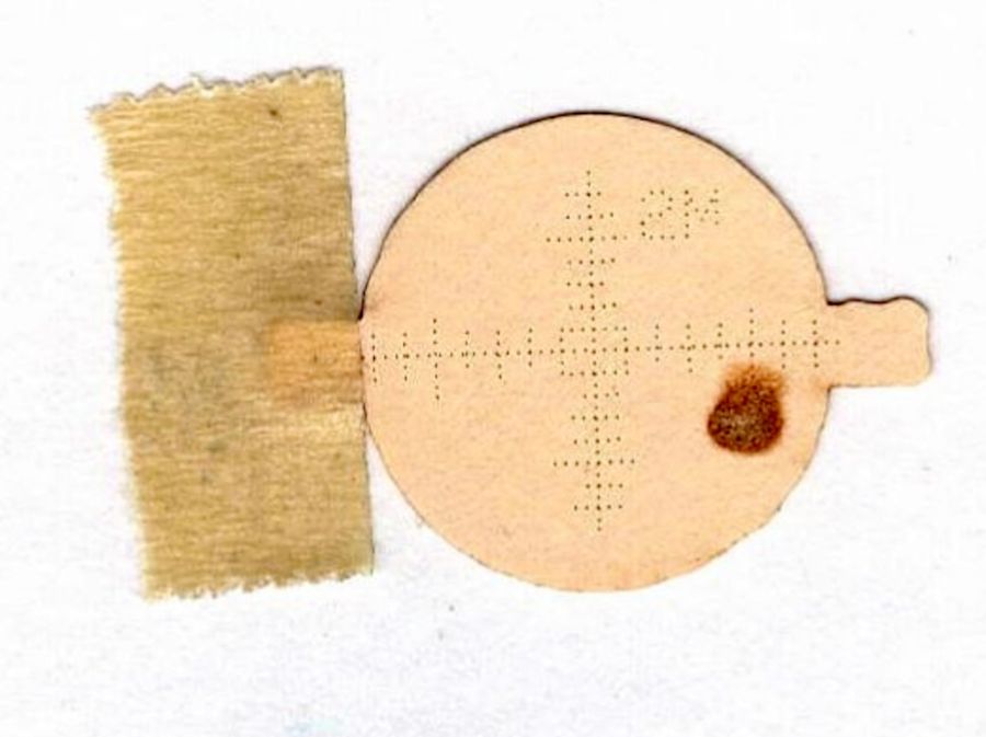
The F target shows the beam position inside the head just above the focus lens:
Beam Alignment – Focus detail – 2023-09-16
The little target in the middle gets centered on the nozzle by feel and shows the beam position within a 2 mm circle. The initial position was off against the side of the nozzle, but slight twiddling of the Mirror 3 screws centered it.
I centered the lower F target at the beam position using the red dot aiming pointer, then pulsed the laser to put a pinhole almost exactly at the graticule center. The larger scorch shows the beam size with the platform lowered 10 mm from the focus level. The Z axis leadscrews are not particularly precise and the platform moves by about a millimeter in X and Y as they rotate, so that’s about as good as it gets.
After all that, the laser behaves at least as well as it ever did and I feel better about having the beamline actually travel along the center of the optical path.
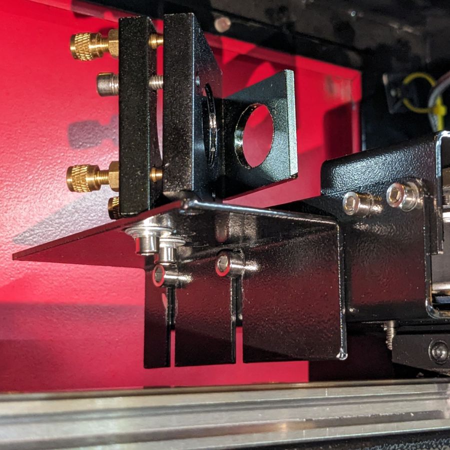
This puts the bracket holding Mirror 2 closer to the center of its x axis adjustment range:
OMTech CO2 Mirror 2 mount – realigned – X screws
Remember, the flange is fixed to the gantry and the bolts move with the mirror mounting bracket.
Raising the laser tube by 5 mm requires Mirror 2 to go upward by a bit to put the beam at the center:
OMTech CO2 Mirror 2 mount – realigned – YZ screws
The least awful way to make simultaneous X and Z axis adjustments seems to be by feel. Tighten the screws just enough to prevent the bracket from moving easily, then slide it while aligning the top edge with respect to the flange on the gantry.
When it feels about right, stick a target to the aperture, fire a pulse, check the results, and iterate until it is actually right.
The two screws holding the mirror mount to the bracket sit in slots allowing some adjustment in the Y axis, as well as a slight amount of rotation. AFAICT, the mount was rotated enough that the test pulses passed through the center of the aperture, but hit the mirror off-center as shown in the top picture. I aligned the aperture parallel with gantry, which should put the holder at 45° to the beamline, and hoped for the best.
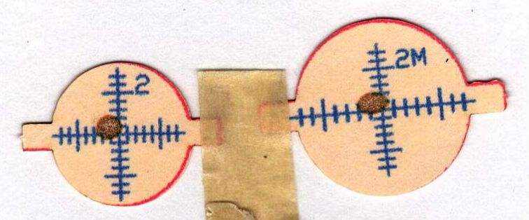
With the pulse mostly centered, twiddle Mirror 1’s alignment to make the beam parallel to the Y axis, which eventually produced these results, with each target getting a pulse at each end of the Y axis travel:
Beam Alignment – Mirror 2 detail – 2023-09-16
Not perfect, but much better than where it started.
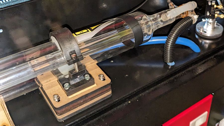
I used an ancient adjustable inside caliper to put the tube the same distance from and aligned parallel to the partition.
Sliding the tube an inch to the left provided enough space to drill & tap two new holes for the Mirror 1 mount to move the beamline 10 mm along the X axis:
OMTech CO2 Mirror 1 mount – redrilled screw holes
I briefly considered crunching rivnuts in there, but the mirror mount expects to sit flat on the floor with no room for rivnuts. So it goes.
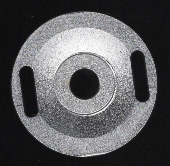
Although Mirror 1’s mount has some vertical adjustment, the central stem was already close to its maximum extension, so I cut a 5 mm plywood pad to raise the base:
Laser Mirror 1 – baseplate scan
Despite what the lighting suggests, it’s concave. The image was clean and contrasty enough to just trace into vectors with LightBurn, then Fire The Laser to cut the spacer:
OMTech CO2 Mirror 1 mount – 5 mm Z shim
If you’re wondering how that worked with the tube jacked up, Mirror 1 sitting on the scanner, and the beamline in disarray, there’s considerable benefit in doing things out of the obvious narrative sequence.
Reassemble the mirror, square the entrance aperture to the partition, fire a couple of test shots to center the mirror on the beamline: