Ed Nisley's Blog: Shop notes, electronics, firmware, machinery, 3D printing, laser cuttery, and curiosities. Contents: 100% human thinking, 0% AI slop.
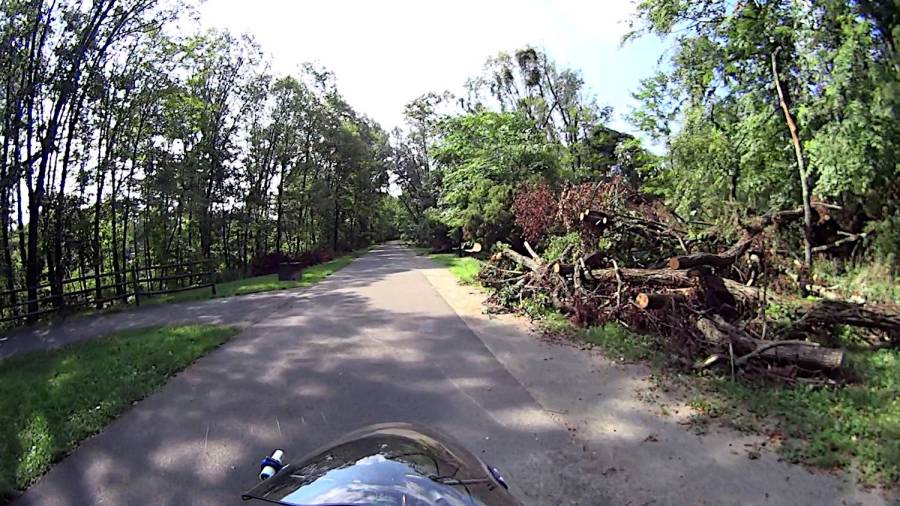
Having an aversion to getting slapped in the face by Blackthorn branches overhanging the Dutchess Rail Trail, I generally give up waiting for anybody else to do the job:
The upper one has a coating of clear rattlecan paint and looks much the better for it. The lower one is bare, but also suffered greatly from being folded and tucked through itself, so it started in worse condition.
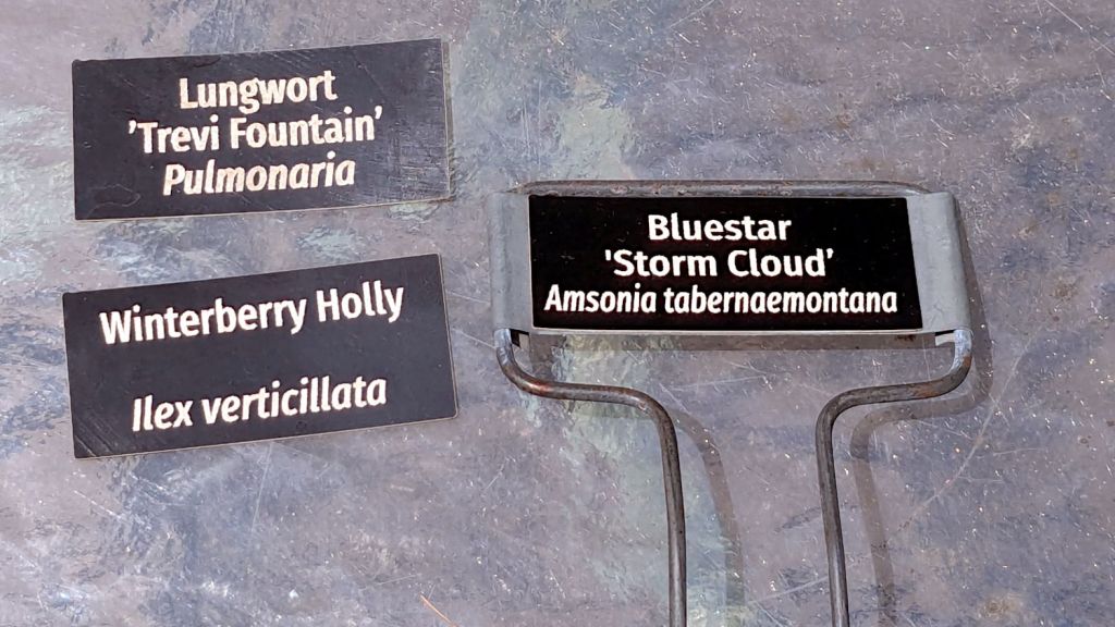
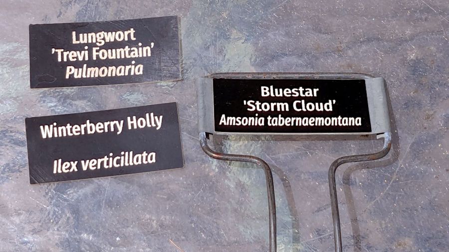
Perhaps the paper will work better when stuck to metal plant label stakes, although I suspect the adhesive sheet will fail first:
Laser test paper – small plant labels
Those are random names; Mary tells me the proper label format has the Latin nomenclature on the first line.
They’re now out on the patio for observation.
For whatever it’s worth, my fascination with this paper boils down to “it’s cheaper than Trolase” for applications not requiring archival quality and duration. If it lasts Long Enough, that’ll be Good Enough.
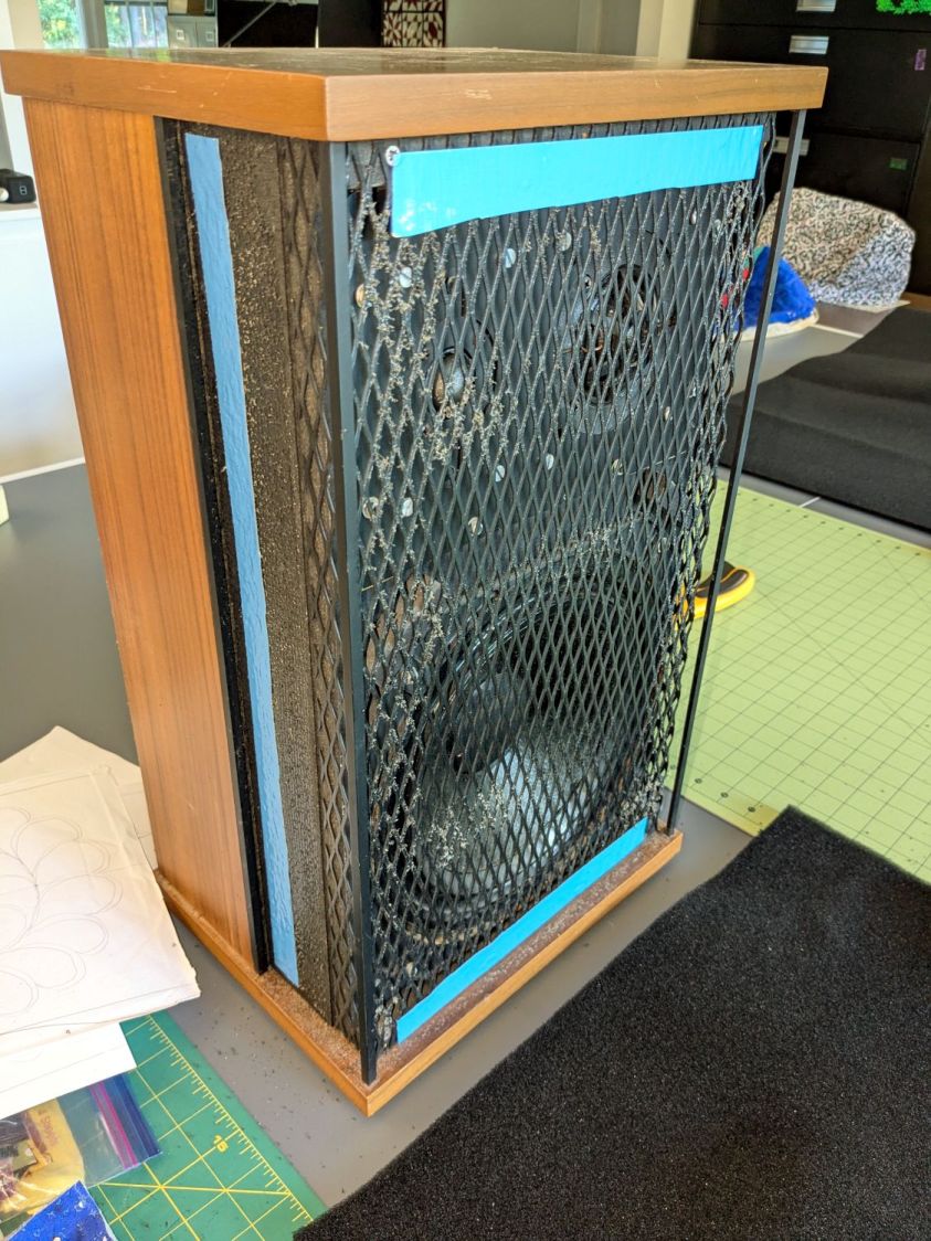
Having recently promoted a pair of Radford Tri-Star 90 speakers to the Sewing Room, it was time to make them presentable:
Radford Tri-Star 90 speakers – taped grill
The original foam grill covering had disintegrated and left fossilized adhesive over the metal gridwork. Being not much for historic accuracy, I used double-sided duct tape (the blue barrier film peels off) and stuck some allegedly acoustic foam in place:
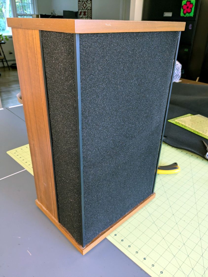
Radford Tri-Star 90 speakers – re-covered
The foam is a single sheet wrapped around three sides and, after some whittling, measured 19.5 inches tall and 19.25 inches wide. The width surely depends on how snugly it’s stretched, so allow a bit more and trim to fit.
Duct tape probably isn’t the right adhesive for the job, but we’ll see how long it lasts. I really did not want to use spray glue and doubted my ability to slobber liquid stickum without oopsing the cones.
The speakers sounded great back in the day and they definitely sound much better than my deflicted ears can hear now. Mary thinks they’re OK and that’s all that matters.
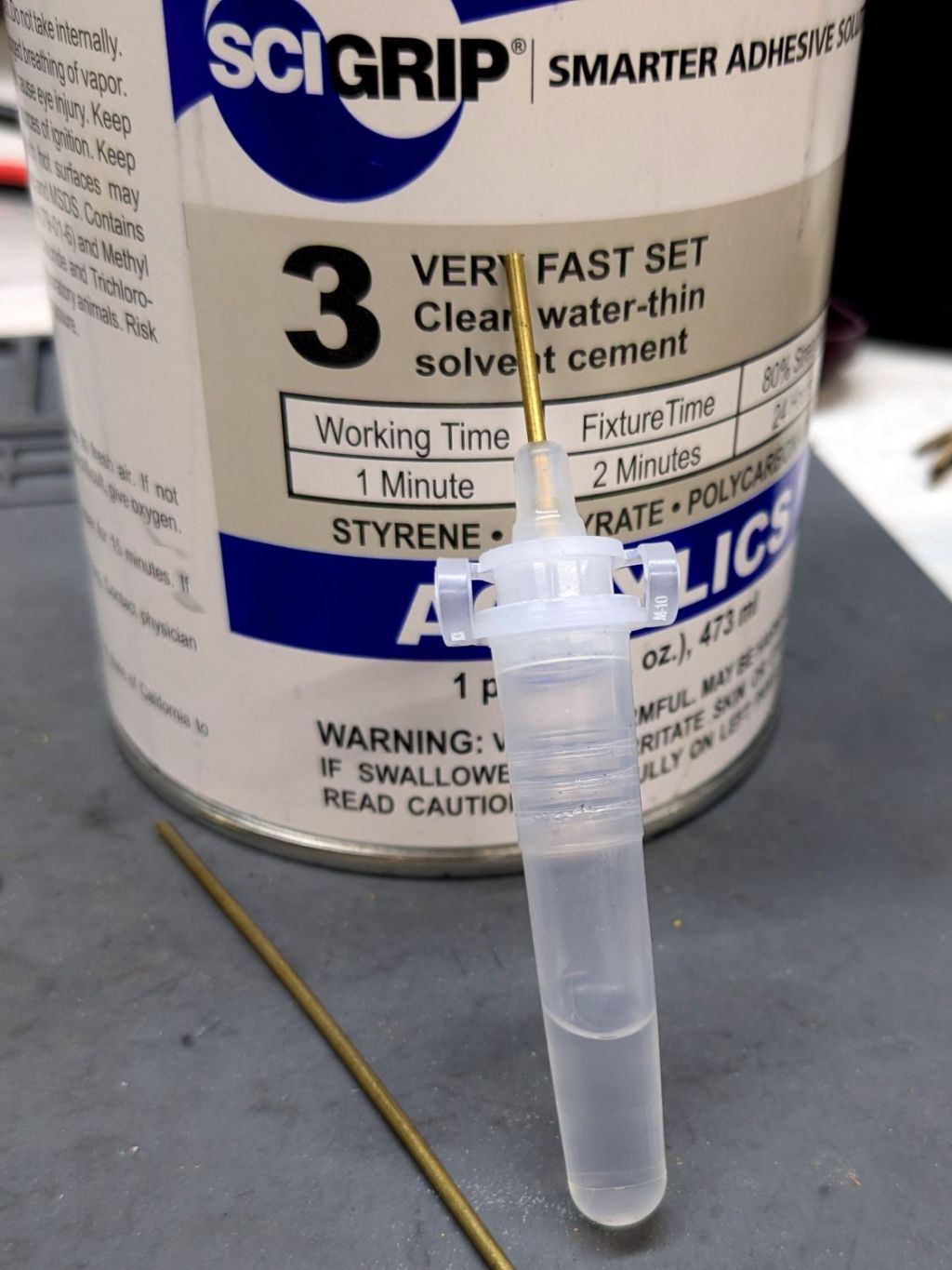
This seemed like a good idea for dispensing small drops of acrylic solvent while gluing spiders together:
COVID test Buffer Extraction Tube – adhesive hack
It’s the Buffer Extraction Tube from a COVID-19 rapid test kit with a short brass tube jammed in its dropper tip. The longer brass tube let me suck that dose of solvent into the tube without any of the hassle required to pour the liquid from a big can into a little tube.
Tell me you didn’t save those things because you thought they didn’t look like they might come in handy for something.
Well, that turned out to be a Bad Idea™, because whatever plastic that tube is made out of cracks when exposed to the hellish mixture in SCIGRIP #3 solvent adhesive. The tube didn’t dissolve or melt, it just cracked when you (well, I) squeezed the sides.
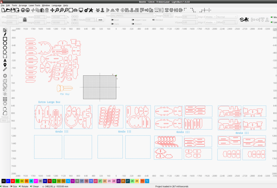
Starting from an SVG file set up for 3 mm material, apply the usual optimizations & tweaks to get a usable LightBurn file, then go nuts:
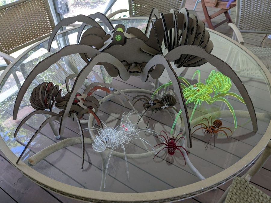
Spider Collection
The big one is two cross-laid layers of corrugated cardboard using up the better part of three Home Depot Large moving boxes:
Spider – LightBurn layout – 2x cardboard
That little bitty grid is the 700×500 mm laser cutter platform, so I just slap a sheet of cardboard in place, update the workspace from the camera, select the next layout, drag it over the cardboard, and Fire The Laser.
The smaller cardboard spider over on the left is built with a single cardboard layer and succumbed to the square-cube law: the legs are entirely too bendy for the weight of the body. Although it’s not obvious from the pictures, both cardboard spiders have a keel plate I added under the body to support most of their weight.
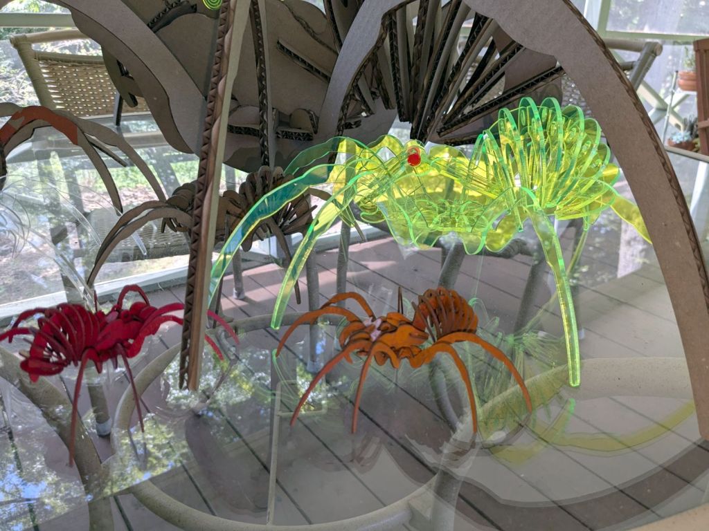
The brightly colored little spiders got a coat of rattlecan paint without any underlying primer and definitely look like that happened:
Spider Collection – detail 2
The edge-lit fluorescent green spider is sized around 2.9 mm material, the clear spider uses 2.3 mm acrylic, and the chipboard one in the background is at 1.8 mm:
Spider Collection – detail 1
The eyes are fluorescent red or green acrylic with concentric circles engraved to catch the light. They’re more effective than I expected, although they won’t look like much after dark.
We now live in a neighborhood with youngsters and Halloween this year will be so much fun …
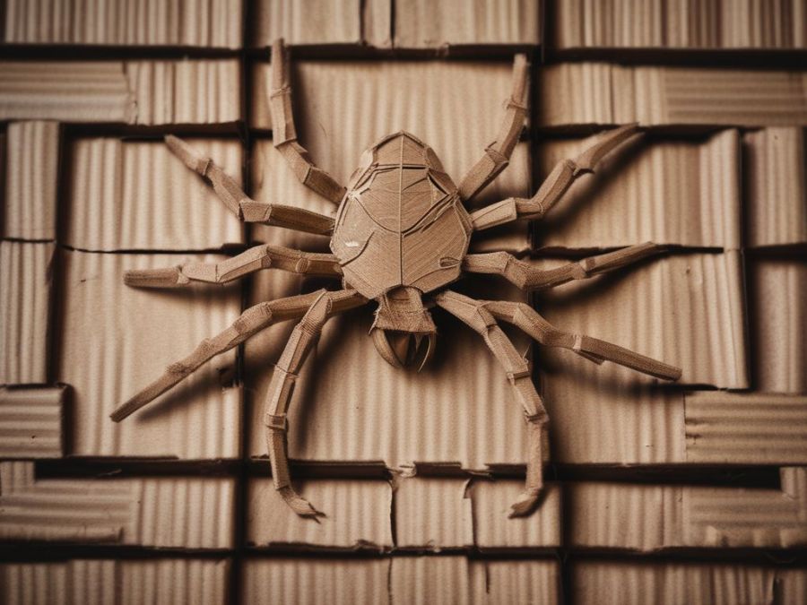
The WordPress AI image generator caught the general idea of “cardboard spiders”:
Everything is held together by ordinary wood glue, squeezed together for a few moments until the two parts no longer slide around.
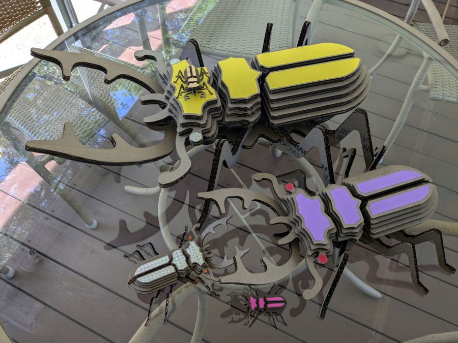
One layer of 3.9 mm corrugated cardboard:
Beetle – 1x cardboard
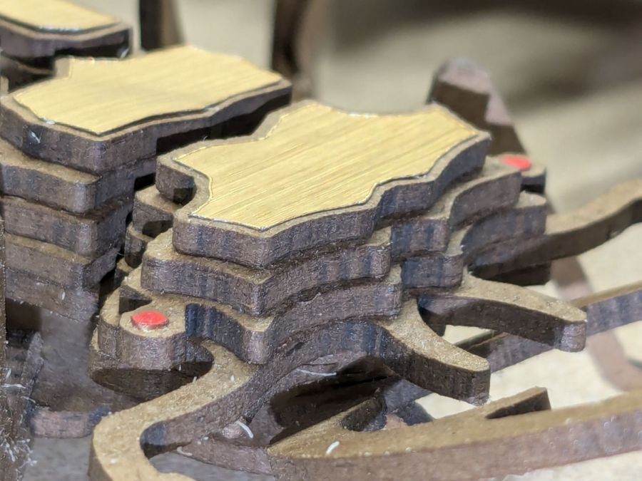
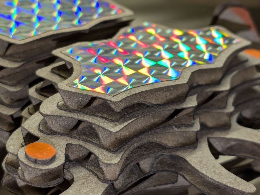
The fancy gold & hologram decorations come from what’s surely non-laser-safe PSA vinyl sheets, cut by offsetting the top layer shapes inward a reasonable amount. The eyes come from random colored paper or painted chipboard.
Two layers of cardboard add up to 8 mm:
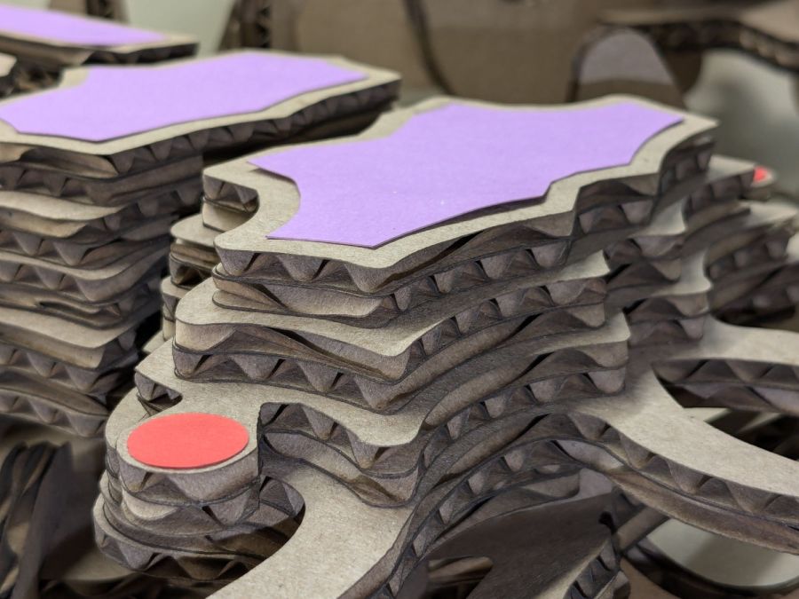
Beetle – 2x cardboard
That’s purple paper left over from the layered paper quilt blocks and, obviously, my glue stick hand is weak.
Three layers of cardboard makes each part half an inch thick: