Ed Nisley's Blog: Shop notes, electronics, firmware, machinery, 3D printing, laser cuttery, and curiosities. Contents: 100% human thinking, 0% AI slop.
We often see Turkey Vultures circling high overhead in thermals rising from, in these parts, sun-heated asphalt parking lots and roads, always on the alert for roadkill. A trio paused for a rest in the trees out front and I managed to get one mediocre portrait against an overcast sky:
Turkey Vulture in tree
They’re staggeringly ugly up close and awkward on the ground, but graceful in their natural element…
The Marlin firmware used by the M2 has these thermistor selections in Configuration.h:
//// Temperature sensor settings:
// -2 is thermocouple with MAX6675 (only for sensor 0)
// -1 is thermocouple with AD595
// 0 is not used
// 1 is 100k thermistor
// 2 is 200k thermistor
// 3 is mendel-parts thermistor
// 4 is 10k thermistor !! do not use it for a hotend. It gives bad resolution at high temp. !!
// 5 is ParCan supplied 104GT-2 100K
// 6 is EPCOS 100k
// 7 is 100k Honeywell thermistor 135-104LAG-J01

#define TEMP_SENSOR_0 1
#define TEMP_SENSOR_1 1
#define TEMP_SENSOR_2 0
#define TEMP_SENSOR_BED 1
The first table in thermistortables.h looks like this:
The OVERSAMPLENR constant determines the number of successive ADC samples added together into a single value, which is then used to search the table for the corresponding entry. The table entries are pairs of: {nominal ADC value * number of samples, temperature in C}
which means that if we know the temperature, we can work backwards to find the ADC value and then compute the actual thermistor resistance.
However, before doing that, I created a modified version of the thermistor table that simply scales the temperatures down by 0.878:
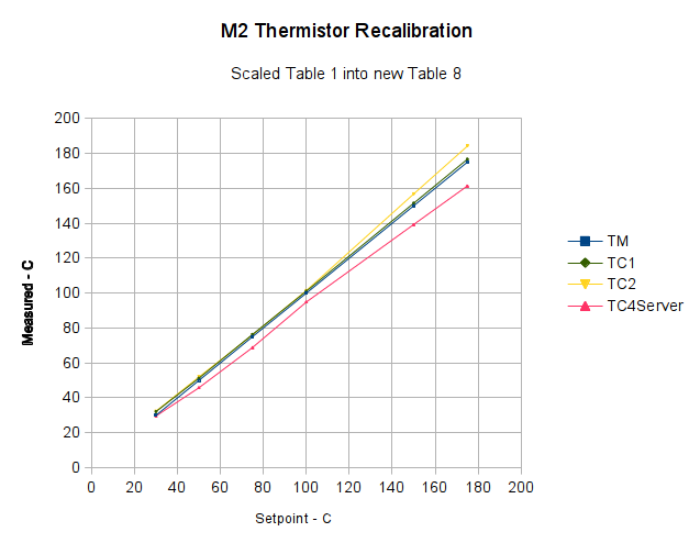
I inserted that table, changed the thermistor selection, reloaded the firmware, and ran the same test as before, which produced this result:
Rescaled extruder thermocouple
The stock thermistor and the thermocouple now report essentially the same values, which is entirely due to the new table. The two additional lines come from two more thermocouples taped to the nozzle and dangling downward toward the platform:
M2 – Hot end with additional thermocouples
Given that I simply taped those thermistors in place, they don’t contact the nozzle nearly as well as the epoxied sensors. The fact that one reads a bit higher and the other much lower could be explained by handwaving, but one possibility is that the various thermocouples don’t quite agree with each other.
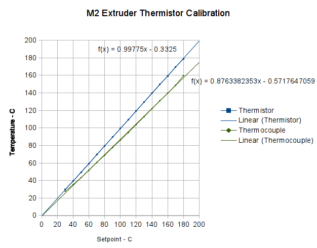
With the stock thermistor and my added thermocouple epoxied to the M2’s nozzle, I stepped the temperature upward, let it settle, and recorded the temperature from the Pronterface status display and my Fluke thermocouple meter:
First Heat – M2 thermistor – Fluke with thermocouple
Because the firmware servos the temperature through the stock thermistor, that line is dead straight at the exact setpoint values: the reference never disagrees with itself. The thermocouple, however, reads low by about 12%: according to it, the nozzle runs much cooler than the thermistor value.
Huh?
Several explanations come to mind:
The firmware is using a lookup table that doesn’t match the thermistor
The Fluke thermocouple meter reports the wrong value
The thermocouple junction is defective
Despite the epoxy blob, the two sensors aren’t at the same temperature
For reasons that, alas, have little to do with normal age-related hearing degeneration, I’ve been wearing Etymōtic (that should be a long o symbol) MP-915 High-definition Electronic Earplugs (aka, Martian Ear Beetles) when I need a 6 dB boost for normal conversations. The key advantage: a price 10 dB under full-throttle hearing aids.
Anyhow, each one runs for about two weeks on a 312 zinc-air primary cell, so I picked up a batch from the usual eBay vendor. These were short-dated, which let me figure out how long after the rated shelf life they’d be good for, so I know what’s the largest batch I should buy.
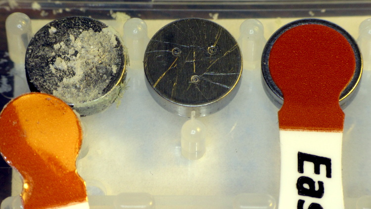
One cell arrived with its air vent seal dislodged:
Corroded zinc-air cell
The cell in the middle is used, with several scratches from the contact point inside the earplug. The cell on the right has a good seal.
Assuming a good seal, the cells seem to work about as well as the long-dated fresh cells included with the earplugs.
Although I found several datasheets (DuracellEnergizerRayovac), there seems to be no way to relate the actual cell you purchase to any particular datasheet; the part numbers do not correspond to anything on the package and the nomenclature varies wildly both between manufacturers and within product lines.
The stock Makergear M2 hot end uses a 100 kΩ thermistor for temperature sensing. A wrap of Kapton tape holds it against the brass nozzle, with a stretchy fiberglass-lined tube for protective insulation and a bit of pressure. This picture shows the tape pocket around the thermistor, with my thumbnail on the left:
The RAMBo board in the M2 has four thermistor inputs and no thermocouple inputs, which surely drove the decision to use themistors. I want to use thermocouples with the LinuxCNC controller, because they’re more compact and happier at higher temperatures.
So I unwrapped the nozzle and lined up a thermocouple beside the thermistor:
M2 – extruder – thermistor-thermocouple
Where a dab of JB Weld firmly bonds them to the nozzle:
M2 – extruder – epoxied sensors
As nearly as I can tell, the JB Weld that I used on the Thing-O-Matic is still going strong. I think the trick is to not apply mechanical force to the bond when it’s hot; secure the leads firmly and use the epoxy only as a thermal connection. Yes, you can get fancy higher-temperature adhesives, but this seems to work well enough.
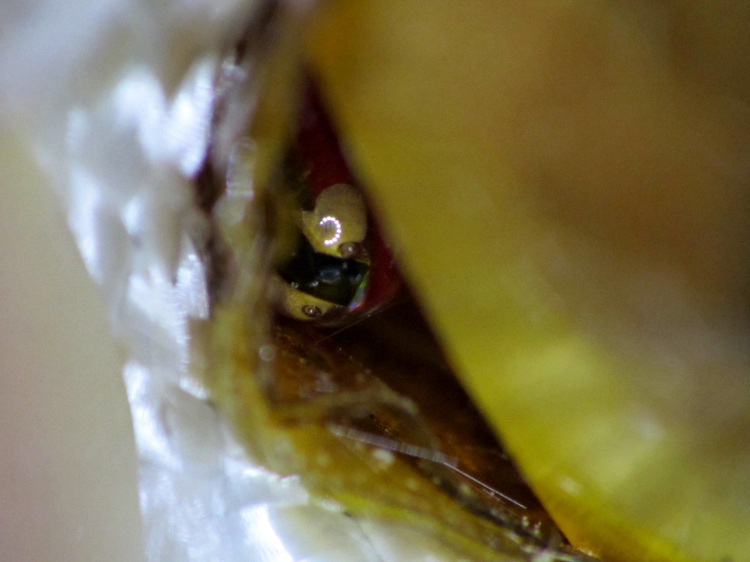
For the moment, I’m using ordinary cotton cloth secured with Kapton tape as insulation:
M2 – extruder – cotton insulation
The brown dot that looks like a bead is actually a flat stain on the nozzle.
Three firmware constants (seem to) control the acceleration applied to each axis, presented here in their original form:
#define DEFAULT_MAX_ACCELERATION      {9000,9000,30,10000}    // X, Y, Z, E maximum start speed for accelerated moves. E default values are good for skeinforge 40+, for older versions raise them a lot.
#define DEFAULT_ACCELERATION          3000    // X, Y, Z and E max acceleration in mm/s^2 for printing moves
#define DEFAULT_RETRACT_ACCELERATION  3000   // X, Y, Z and E max acceleration in mm/s^2 for r retracts
I do not pretend to understand their interaction and, pursuant to that discussion, some tests and measurements seem to be the only way to find out what’s happening. However, estimating some masses and guesstimating motor performance can put some boundaries on the problem.
Based on weighing a slightly larger stepper motor and the hot end, the complete extruder assembly may weigh (OK, mass) about 600 grams, which I’ll round up to 1 kg to cover bending the filament guide tube and friction. In order to accelerate the extruder carriage at 9000 mm/s^2, the X axis stepper motor force must be:
F = ma = 1 kg * 9 m/s2 = 9 N
The pulley drives 36 mm of belt per revolution, so the effective diameter = 11.5 mm and the radius = 5.7 mm. That means the motor torque will be:
50 mN·m = 9 N * 5.7 mm
I don’t have specs for the Makergear motors, but similar motors have pull-in torques in the 200 to 300 mN·m range, which is flat out to 1000 (full)step/s and decreases to zilch as the speed approaches 10000 (full)step/s. Because the motors run in 1/16 microstep mode, Marlin’s peak 40000 (micro)step/s rate works out to 2500 (full)step/s, where the motor pull-in torque is maybe half of the maximum.
The motor pull-out torque falls off to nothing around 1000 (full)step/s = 16000 (micro)step/s, which suggests you can’t slow the stages down nearly as fast as you speed them up, at least beyond about 10000 (micro)step/s.
All of that depends on the motor current, of course, and that depends on the amount of heat you’re willing to generate in the motors. I really must build a better dynamometer.
Assuming the Y stage + heater + glass weighs 4 pounds = 2 kg, the numbers are twice as large, but they’re in the same ballpark.
I tried a few values for the Z acceleration and settled on something slightly larger, but that won’t apply to a different motor.
I have no way to estimate the force required to drive the filament, but the gearbox multiplies the motor torque by a factor of 5, so there’s a speed-torque tradeoff lying in wait.
I modified the acceleration constants to bring the overall limits in line with the per-axis values:
#define DEFAULT_MAX_ACCELERATION      {9000,9000,75,10000}
#define DEFAULT_ACCELERATION          10000		// X, Y, Z and E max acceleration in mm/s^2 for printing moves
#define DEFAULT_RETRACT_ACCELERATION  10000		// X, Y, Z and E max acceleration in mm/s^2 for r retracts
Changing the last two values from 3000 to 10000 produced a dramatic increase in acceleration, so those numbers do act as overall limits on the per-axis values in the first line.
Because the motion planner ramps the velocity up at the maximum possible acceleration (reduced, as needed, to accommodate the motor with the lowest acceleration involved in the motion), higher acceleration values allow the motor to reach the desired speed sooner, so shorter motions run faster.
For example, reaching 200 mm/s2 from a standing start requires 6.7 mm at 3000 mm/s2 and 2.2 mm at 9000 mm/s2. Braking to a stop requires the same distance, assuming the pull-out torque allows it. Contemporary motion planners that can match velocities around corners where straight-line segments join will allow higher sustained speeds, so they don’t require slowing to a dead stop.
But, of course, the 3D printer’s overall structure must be rigid enough to restrain the reaction forces caused by high accelerations and the printer must be anchored well enough to not sidle off the table. The M2 can handle a single high-speed move, but chaining multiple moves together shakes the steel chassis rather violently; that happens when you select the Slic3r “Avoid crossing perimeters” option.