Ed Nisley's Blog: Shop notes, electronics, firmware, machinery, 3D printing, laser cuttery, and curiosities. Contents: 100% human thinking, 0% AI slop.
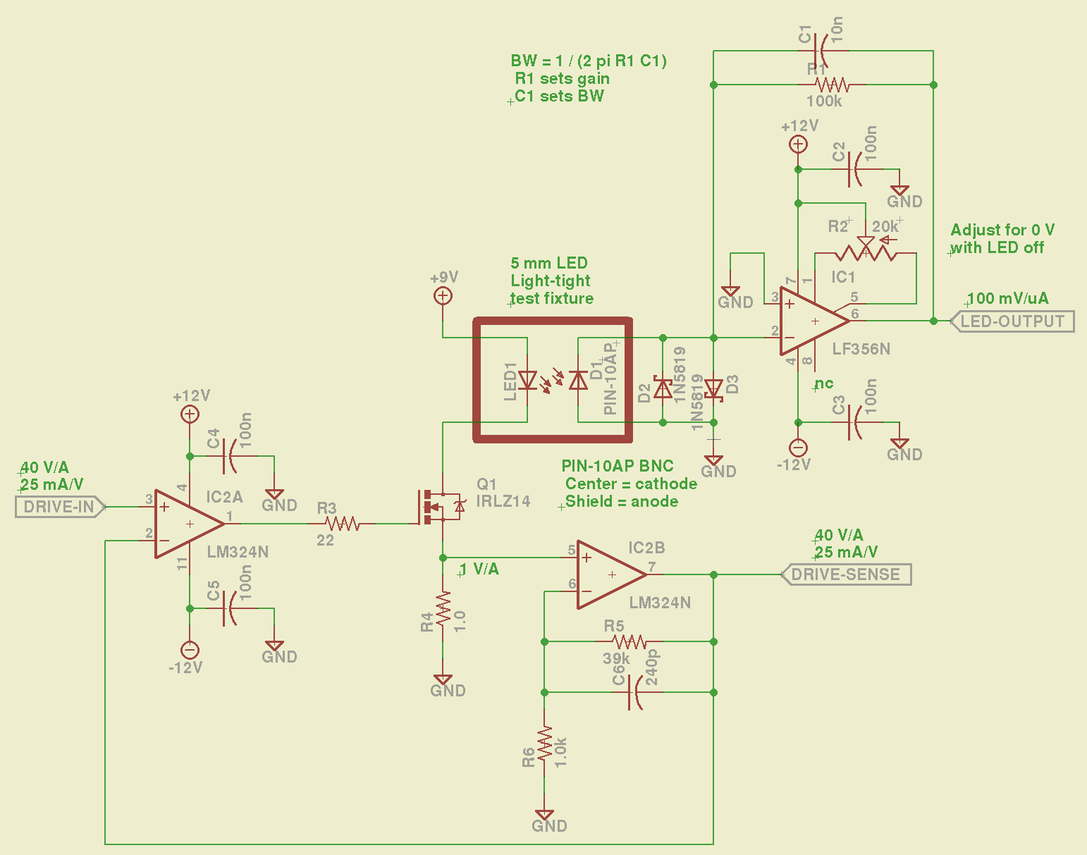
The LM324 converts the input voltage to an LED drive current, scaled by the sense resistor and the gain of IC2B to 25 mA/V. The feedback loop closes through the MOSFET and C6 rolls off the response, so there’s a nasty overshoot on the leading edge of input pulses where the current increases faster than the op amp can tamp it down:
Red LED – 25 mA 14 uA
The LM356 acts as a transimpedance amplifer to convert the photodiode current to voltage. The PIN-10AP specs say it should operate in photovoltaic mode with zero bias and that more than -3V of bias will kill the photodiode; the LM356 should hold its inverting input at virtual ground, but the two 1N5819 Schottky diodes enforce that limit. There being zero volts across the diodes, they don’t leak in either direction, so it’s all good.
The circuit is an embarrassing hairball on solderless breadboard, so use your imagination…
You could mash this together with the LED Curve Tracer, although you’d want better low-current resolution from the Arduino output.
I mentioned to my doctor that, if I were of malign intent, I would now have complete control of every PC on their network. That didn’t make much of an impression, as the same thing happened on my next visit.
Of course, moving to electronic records makes a lot of sense, but if you think they’ll be any more secure than any other online personal information, you’re wrong.
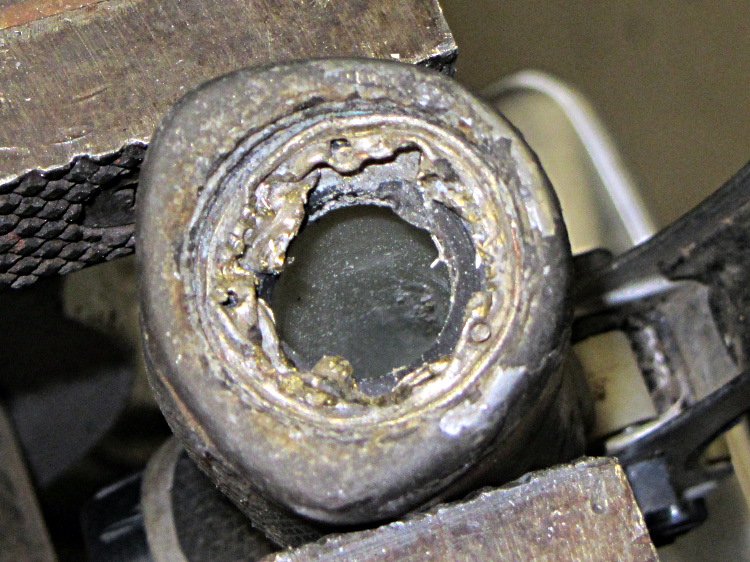
The hose attached to this garden sprayer had failed last season, but the hose fitting had become one with the sprayer. Soaking it with penetrating oil for far longer than seemed necessary didn’t help, so I tried brute force:
Garden sprayer hose fitting
After convincing myself that wasn’t going to work, I cut the fitting off and tried the old standby of collapsing the threaded shell inward with a small punch:
Garden sprayer – rolled-in fitting
That didn’t work, either: the shell really had become one with the sprayer.
As it turned out, the plastic sprayer body had begun to crack in several high-stress locations and would shortly become Yet Another Project. I cut my losses and tossed the hose and the sprayer.
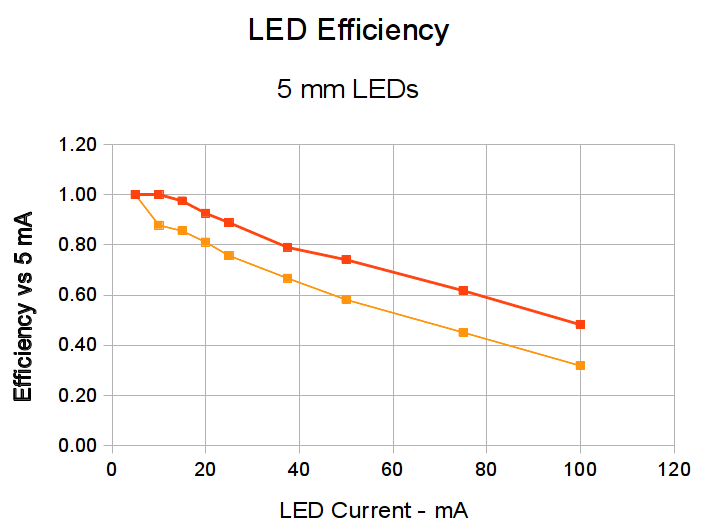
Given that test fixture, the obvious question is whether the PIN-10AP photodiode’s output current varies linearly with light intensity, just like the specs would lead you to believe. I excavated the sheet of 2-stop neutral density filter gel from the Parts Warehouse Wing and cut some 30 mm disks:
LED Photodiode test fixture – ND filter disks
A single filter layer should reduce the light intensity by 2 f/stops = a factor of 4. Each successive layer reduces the intensity by another factor of 4. They’re all at least reasonably clean and free of defects, but they’re definitely not optical lens quality.
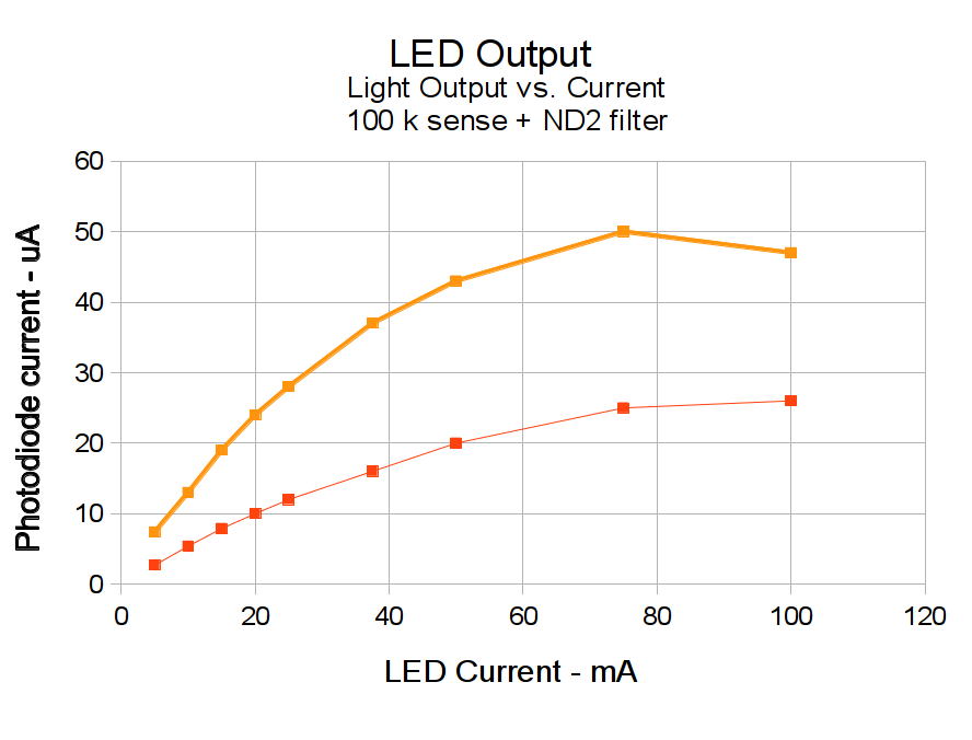
Running the LED with a 100 mA pulse at 20% duty cycle and stacking the disks in the fixture, one by one, between the LED and photodiode, produces this data:
Layers
Attenuation
Scale
V
I – uA
Ratio
0
1
1.0000
8.7
87
1
4
0.2500
1.9
19
4.58
2
16
0.0625
0.43
4.3
4.42
3
64
0.0156
0.097
0.97
4.43
4
256
0.0039
0.022
0.22
4.41
The Ratio column divides successive pairs of current values. The first step, from “no filter” to “one filter”, came out a bit larger than the rest, probably because the gel sheet isn’t anti-reflective and some light bounces off the top.
After that, though, it looks just like I’m cheating, doesn’t it?
The ratios should be 4.0, but the actual 4.4 means it’s a 2.1 stop filter. Close enough, methinks.
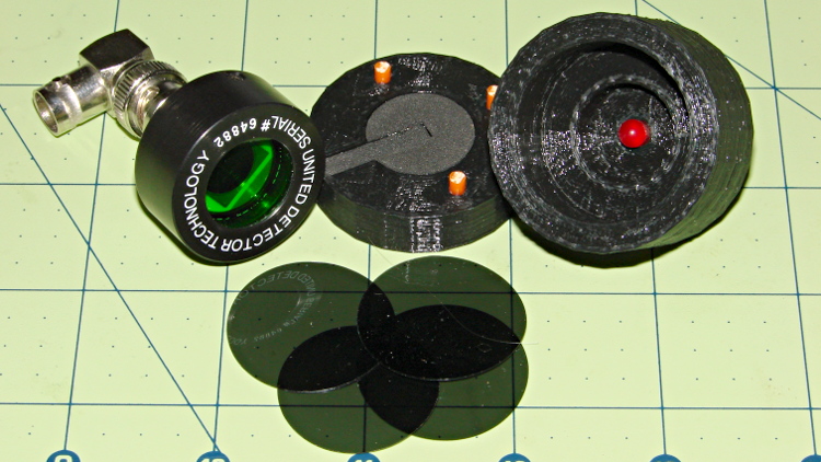
An upcoming Circuit Cellar column calls for a way to measure LED light output vs. current input, which means I need some way to hold LEDs directly over a photodiode while excluding ambient light. Fortunately, the M2 had black PLA filament already loaded:
LED Photocell Fixture – parts
That honkin’ big photodiode is a surplus PIN-10AP that’s been lying in wait for an opportunity just like this. The green filter matches the silicon response to CIE-standard human eye sensitivity, so the output tracks what you’d actually see. That’s irrelevant for testing red LEDs that all have pretty much the same wavelength, but it might come in handy for something.
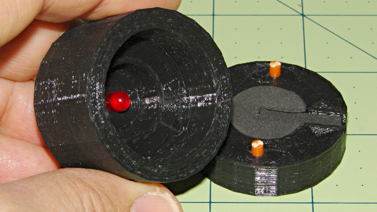
The main body of the fixture holds the LED about 1 mm from the front of the photodiode, indexed against the LED flange so they’re all at a consistent location. The cap has three locating pins made of 3 mm orange filament, with black foam rubber to push the LED into position and block ambient light.
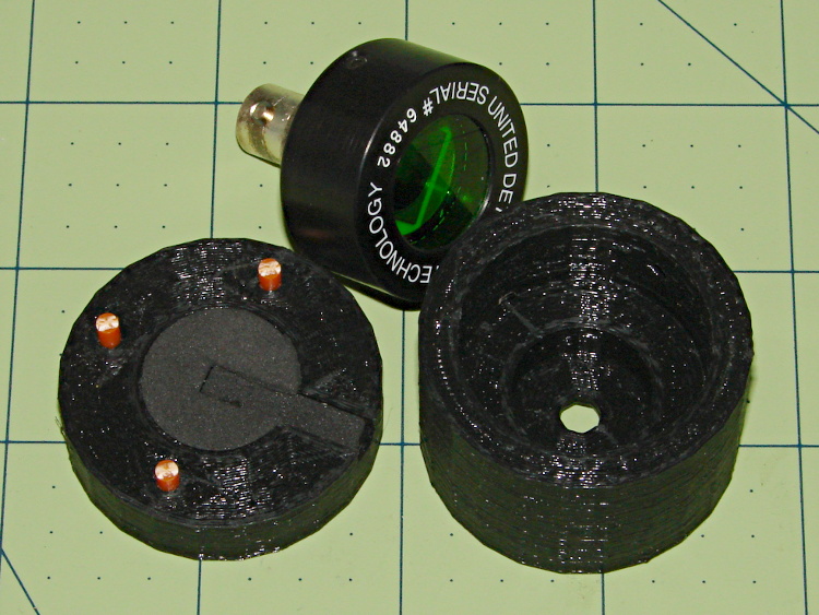
The business end looks like this:
LED Photocell Fixture – LED view
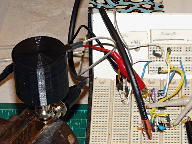
The most convenient way to mount the thing involves a right-angle BNC adapter in my trusty bench vise:
LED Photocell Fixture – with breadboard
The circuitry has a voltage-to-current driver for the LED and a zero-bias current-to-voltage converter for the photocell. The zero-bias trick keeps the voltage across the photodiode at zero, so the current varies linearly with illumination.
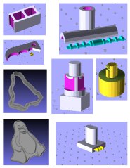
The solid model laid out for printing along the X axis:
LED Fixture for PIN-10AP Photodiode – solid model overview
It obviously has some improvements over the as-printed one in the pictures, in the unlikely event I need another fixture. The most important: a rear ring covering the back of the photodiode. Turns out that the PIN-10AP filter cap leaks a surprising amount of light around the body; I covered the gap with black tape to make the measurements, but that’s crude.
I added a few screw holes to hold the parts together, but the cap (with the foam and pegs) must come off easily while swapping LEDs. I’d be tempted to sink studs into the body and use wing nuts to hold the lid in place, but I don’t have any 4-40 wing nuts…
There’s a tiny bit of support under the central hole to support the LED flange recess and the trench for some foam under the leads:
LED Fixture for PIN-10AP Photodiode – support
That’s another improvement; the as-printed one has foam on only one side of the leads.
The OpenSCAD source code:
// LED test fixture for PIN-10AP photodiode
// Ed Nisley KE4ZNU May 2013

// Layouts: Adapter AdapterSupport Cap Shield Build Show

Layout = "Build";

Gap = 8;		// between parts in Show

//- Extrusion parameters must match reality!
//  Print with +1 shells and 3 solid layers

ThreadThick = 0.25;
ThreadWidth = 0.40;

HoleWindage = 0.2;

function IntegerMultiple(Size,Unit) = Unit * ceil(Size / Unit);

Protrusion = 0.1;			// make holes end cleanly

Spacing = 5;				// between parts on build platform

inch = 25.4;

Tap2_56 = 0.070 * inch;
Clear2_56 = 0.082 * inch;
Head2_56 = 0.156 * inch;
Head2_56Thick = 0.055 * inch;

//----------------------
// Dimensions

PhotoDiodeOD = 31.3;
PhotoDiodeStemOD = 16.0;
PhotoDiodeStemLength = 8.0;
PhotoDiodeWindowDia = 17.7;
PhotoDiodeHeight = 14.0;

FixtureOD = PhotoDiodeOD + 2*7.0;

LEDDia = 5.0;				// LED body
LEDFlangeOD = 6.0;			// flange at base of LED
LEDFlangeThick = IntegerMultiple(1.5,ThreadThick);
LEDLength = 10.0;			// overall length
LEDRecess = 4.0;			// tube to fit LED body
LEDSides = 8;

FixtureLength = PhotoDiodeHeight + LEDLength + IntegerMultiple(1.0,ThreadThick);

CapLength = 15.0;			// LED cover

FoamOD = FixtureOD/2;
FoamThick = IntegerMultiple(2.0,ThreadThick);

TrenchDepth = 2*FoamThick;
TrenchWidth = LEDDia;

ShieldThick = 5.0;
ShieldScrewCircle = PhotoDiodeOD + (FixtureOD - PhotoDiodeOD)/2;

PinOD = 3.0;				// alignment pin (filament)
PinLength = 10.0;			//   ... total length
PinCircle = FixtureOD/2;

GrubScrewOD = Tap2_56;

$fn=4*6;					// default cylinder sides

//----------------------
// Useful routines

module PolyCyl(Dia,Height,ForceSides=0) {			// based on nophead's polyholes

  Sides = (ForceSides != 0) ? ForceSides : (ceil(Dia) + 2);

  FixDia = Dia / cos(180/Sides);

  cylinder(r=(FixDia + HoleWindage)/2,
           h=Height,
	   $fn=Sides);
}

module ShowPegGrid(Space = 10.0,Size = 1.0) {

  RangeX = floor(95 / Space);
  RangeY = floor(125 / Space);

	for (x=[-RangeX:RangeX])
	  for (y=[-RangeY:RangeY])
		translate([x*Space,y*Space,Size/2])
		  %cube(Size,center=true);

}

//-----------------------
// Parts

module Adapter() {

	difference() {
		cylinder(r=FixtureOD/2,h=FixtureLength);
		translate([0,0,-Protrusion]) {
			PolyCyl(LEDDia,2*FixtureLength,LEDSides);
			PolyCyl(PhotoDiodeWindowDia,(FixtureLength - LEDRecess + Protrusion));
			PolyCyl(PhotoDiodeOD,(PhotoDiodeHeight + Protrusion));
		}
		translate([0,0,(FixtureLength - LEDFlangeThick)])
			PolyCyl(LEDFlangeOD,2*LEDFlangeThick,LEDSides);
		translate([FixtureOD/2,0,(FixtureLength + FoamThick/2 - LEDFlangeThick)]) {
			cube([FixtureOD,TrenchWidth,FoamThick],center=true);
		}
		for (angle = [90:90:270])
			rotate(angle)
				translate([0.75*PinCircle,0,(FixtureLength - PinLength/2)])
					PolyCyl(PinOD,PinLength,6);
		for (angle = [0:120:240])
			rotate(angle)
				translate([ShieldScrewCircle/2,0,-Protrusion])
					rotate(45)
						PolyCyl(Tap2_56,(ShieldThick - 6*ThreadThick + Protrusion));
		if (0)
			translate([0,0,FixtureLength/4])
				rotate([0,90,0])
					PolyCyl(GrubScrewOD,FixtureOD);
	}

}

module AdapterSupport() {

spiderthick = IntegerMultiple(LEDFlangeThick - ThreadThick,ThreadThick);

	color("Yellow")
		union() {
			for (leg = [0:LEDSides/2 - 1])
				rotate(leg*360/LEDSides)
					translate([0,0,spiderthick/2])
					cube([(LEDFlangeOD - 0.5*ThreadWidth),
							2.5*ThreadWidth,
							spiderthick],
							center=true);
			cylinder(r=LEDDia/2,h=spiderthick,$fn=LEDSides);
			for (bar = [-1:1])
				translate([LEDDia/3,(bar*3*ThreadWidth - ThreadWidth),0])
					cube([FixtureOD/2,2*ThreadWidth,IntegerMultiple(LEDFlangeThick - ThreadThick)]);
		}
}

module Cap() {

	difference() {
		cylinder(r=FixtureOD/2,h=CapLength);
		translate([(FixtureOD/2 - LEDDia/2),0,CapLength]) {
			cube([FixtureOD,TrenchWidth,2*TrenchDepth],center=true);
		}
		translate([0,0,(CapLength - FoamThick)])
			PolyCyl(FoamOD,(FoamThick + Protrusion));
		for (angle = [90:90:270])
			rotate(angle)
				translate([0.75*PinCircle,0,(CapLength - PinLength/2)])
					PolyCyl(PinOD,PinLength,6);
	}

}

module Shield() {

	difference() {
		cylinder(r=FixtureOD/2,h=ShieldThick);
		translate([0,0,-Protrusion])
			PolyCyl(PhotoDiodeStemOD,(ShieldThick + 2*Protrusion));
		for (angle = [0:120:240])
			rotate(angle) {
				translate([ShieldScrewCircle/2,0,-Protrusion])
					rotate(180/5)
						PolyCyl(Clear2_56,(ShieldThick + 2*Protrusion));
				if (0)
				translate([ShieldScrewCircle/2,0,(ShieldThick - 1.5*Head2_56Thick)])
					rotate(180/6)
						PolyCyl(Head2_56,4*Head2_56Thick);
			}
	}
}

//-------------------
// Build it...

ShowPegGrid();

if (Layout == "Adapter")
	Adapter();

if (Layout == "Cap")
	Cap();

if (Layout == "Shield")
	Shield();

if (Layout == "Show") {
	translate([0,0,(ShieldThick + Gap)]) {
		translate([0,0,FixtureLength + CapLength + Gap])
			rotate([180,0,0])
				Cap();
		Adapter();

		color("Orange")
		for (angle = [90:90:270])
			rotate(angle)
				translate([0.75*PinCircle,0,(FixtureLength + Gap - PinLength/2)])
					PolyCyl(PinOD,PinLength,6);
	}

	Shield();
}

	if (Layout == "AdapterSupport") {
	translate([0,0,FixtureLength])
		rotate([180,0,0])
			%Adapter();
	AdapterSupport();
}

if (Layout == "Build") {
	translate([(Spacing + FixtureOD),0,0]) {
		translate([0,0,FixtureLength])
			rotate([180,0,0])
				Adapter();
		AdapterSupport();
	}
	translate([0,0,0])
		Cap();

	translate([-(Spacing + FixtureOD),0,0])
		Shield();
}