Ed Nisley's Blog: Shop notes, electronics, firmware, machinery, 3D printing, laser cuttery, and curiosities. Contents: 100% human thinking, 0% AI slop.
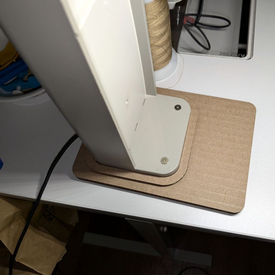
It’s not particularly elegant, what with being cardboard, but it’s a proof of concept that will determine the final size.
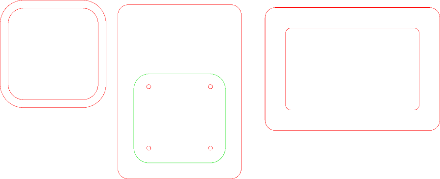
The top layer is a ring around the lamp pedestal for a bit of stabilization protecting the four M3 screws holding the base to the lamp. Those screws sit on a 60 mm square, offset 1 mm to the front of the lamp:
NisLite Baseplate – LightBurn layout
Which explains why I typically make the first few versions of anything out of cardboard.
For the record, those inserts look like this:
Converted Ottlite – brass inserts
A pair of very flat-head M3 screws hold the front inserts in place through holes match-drilled in the remains of the bosses I’d long ago epoxied in place. I pressed the rear inserts in place by misusing the drill press, as the lamp is much too tall for the heat setter.
Then comes the iron base weight:
Converted Ottlite – iron weight
And then the steel outer plate:
Converted Ottlite – steel cover plate
The new base plate gets a ring around its perimeter for clearance under the four pan head M3 screws into the inserts.
If the cardboard base is stable enough, we’ll do an acrylic version in cheerful primary colors.
The LightBurn layout in SVG format as a GitHub Gist:
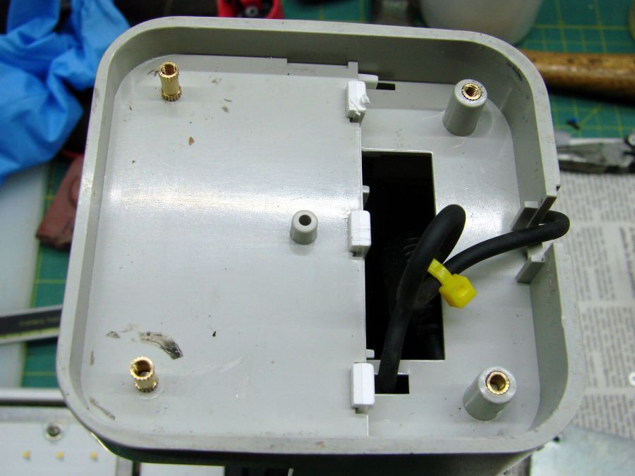
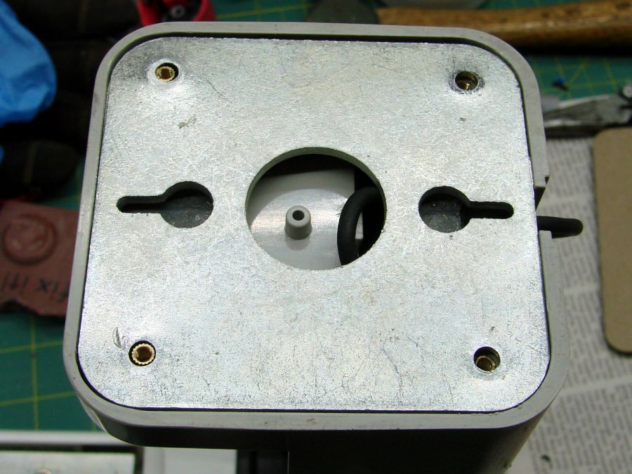
While cleaning dead bugs out of the ceiling lamps, we discovered the kitchen light was missing one of the three nuts holding its cover in place. While spare nuts might be available, this seemed like a quicker & easier solution:
Ceiling Lamp Nut – bottom view – solid model
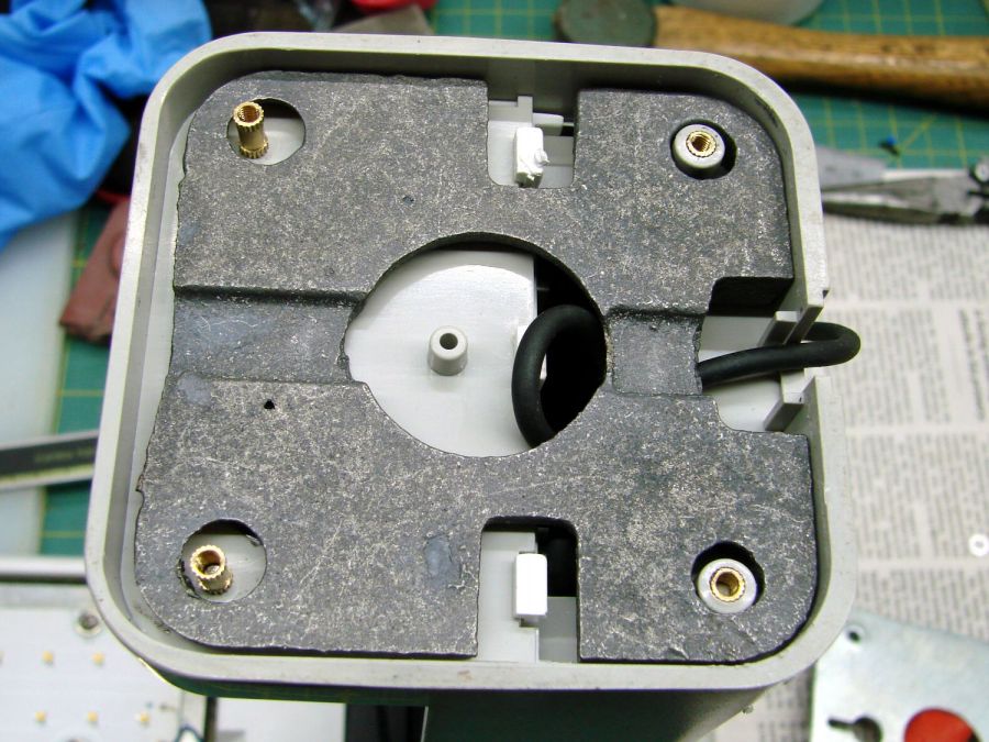
The stepped interior fits a brass insert with 8-32 threads (not metric, to my utter astonishment) rammed in place with a heat-set tool:
Ceiling Lamp Nut – insert staking
Using the nominal diameters seems to work fine, although I’m sure some finesse will be needed with smaller inserts.
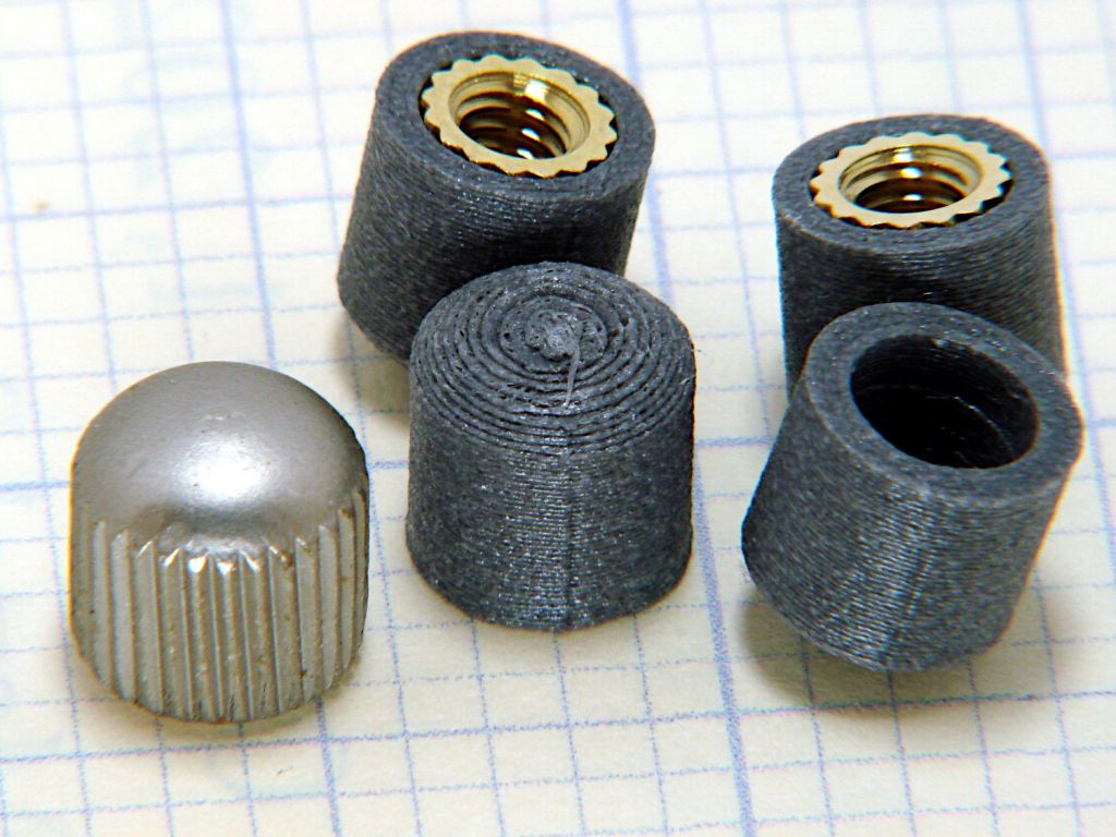
Printed four just to be sure, rammed three inserts, and they’re ready:
Ceiling Lamp Nuts – as-built
The curved cap matches the original nut through the use of the Chord Equation to get the cap radius as a function of its height (sagitta) & base diameter. Admittedly, it looks kinda grotty with only a dozen layers, but it’s the thought that counts.
The original nuts are heavy knurled steel and the new ones are cheap plastic, but nobody will ever know:
Ceiling Lamp Nut – installed
Bonus: now I have two spare steel nuts for the next time …
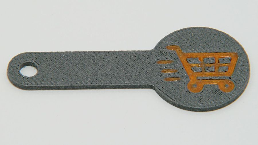
Making laser-cut cart coins is much faster than 3D printing
The LightBurn layout looks like this:
Cart coin – LightBurn screen shot
The red lines show cuts through the material to produce the overall shape with a hole for a keyring. The black areas show where the laser will raster-scan the surface at lower power to engrave the cart logo, which consists of vector outlines traced from a PNG file.
Presumably the other elements are still in there, but they’re hidden inside the outline and can’t be manipulated separately in OpenSCAD.
OpenSCAD can pick out named elements, groups, or layers from the SVG file, but, alas, the LightBurn SVG file has no named items, as shown in this chunk:
So I copied that LightBurn design to put the shapes on two different layers marked for Fill processing:
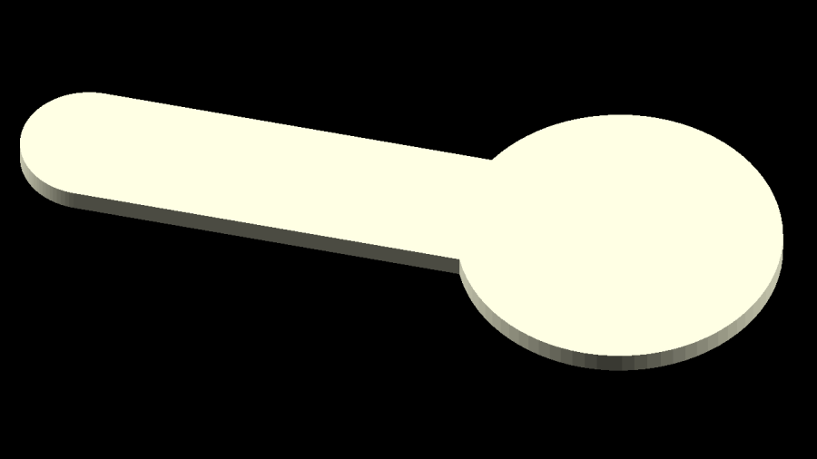
The coin-with-handle
The cart logo
It’s not absolutely necessary to use Fill layers, but they make it easier for me to visualize the shapes as solid objects.
Subtracting the keyring hole and the cart logo from the overall coin-with-handle produces a single shape (with holes) for one material, plus the logo shapes in another material:
Cart coin – separated – LightBurn screen shot
Put the logo back in position before proceeding:
Cart coin – overlaid – LightBurn screen shot
Unlike the first LightBurn layout, these two layers won’t cut & engrave a cart coin: they define the shapes in such a way that OpenSCAD can turn them into 3D solid models. It’s straightforward to convert between those layouts and they can reside in the same LightBurn file as the original design; just select the one you want to burn or export, as needed.
Note that LightBurn and Inkscape use the term “layer” in completely different ways:
A LightBurn layer defines the laser control settings for all the geometry in that layer
An Inkscape layer collects a bunch of shapes into a logical group, but does not otherwise influence them
In particular, even though we now have objects in two different layers, the exported LightBurn SVG file still has no names for those layers. Fixing that requires a trip through Inkscape.
Export the filled layout from LightBurn and open (or import) that SVG file with Inkscape, which automagically names the paths:
Inkscape auto-generated path names
In order from 5 down to 1, those paths correspond to:
The cart logo
Three go-fast stripes
The coin-with-handle outline with various holes
Create two layers with memorable names, then move the appropriate paths into those layers:
Cart Coin – Inkscape layer definitions
Save the Inkscape layout as an Inkscape SVG file, which will have contents something like this snippet:
Note the inkscape:label="Coin" and inkscape:label="Logo" stanzas corresponding to the layers.
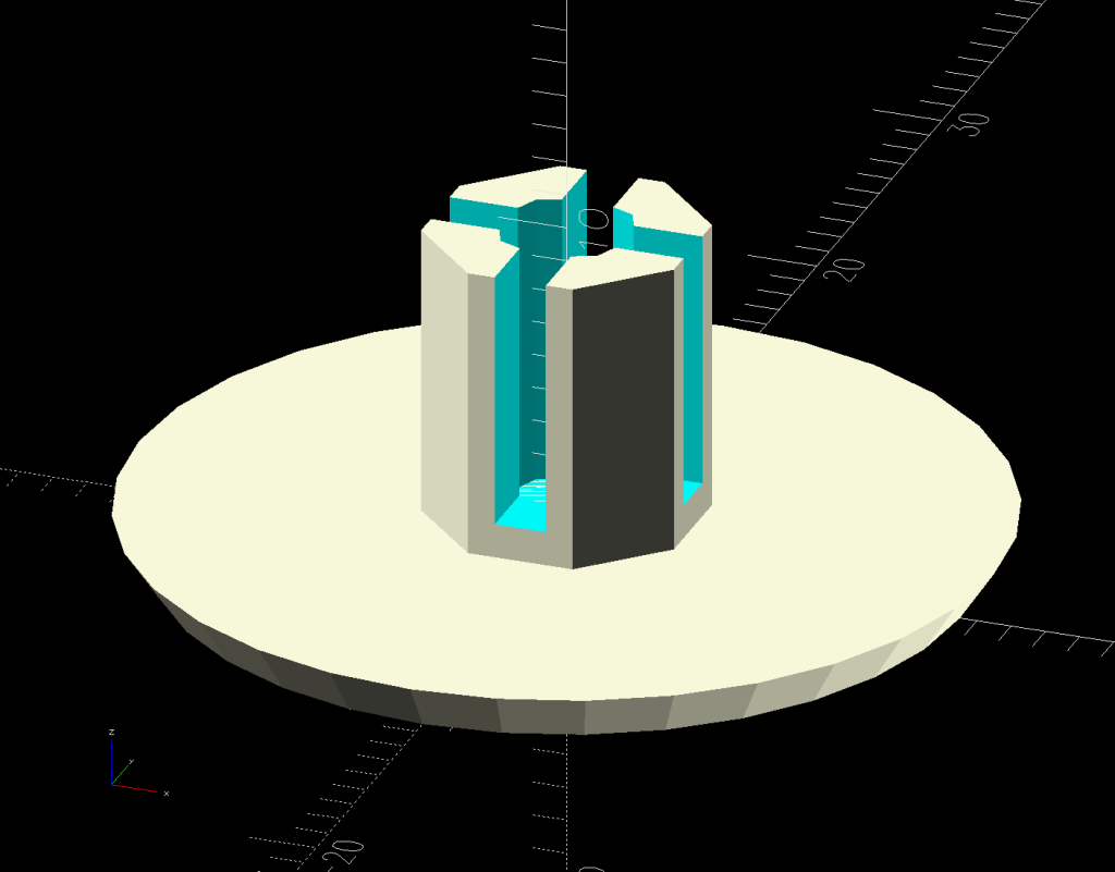
Import that SVG file into OpenSCAD twice, once to extract each layer by name, extrude the 2D shapes to form a solid model with two parts, and give them distinctive colors:
The cart logo exactly fills the matching holes in the coin shape, but because it’s a different OpenSCAD object, it won’t merge with its surroundings.
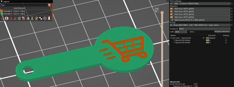
Export that model in 3mf format, because it seems better than stl for multi-material models, import it into PrusaSlicer, and get a helpful alert:
PrusaSlicer multi-material alert
Yes, do that thing, then assign the appropriate filament to each object:
PrusaSlicer cart coin preview
Arrange half a dozen instances on the platform and make yourself a set of cart coins:
Blue cart coins on platform
Now, the obvious question: “Why not just do this in Inkscape, set up all the layers for OpenSCAD, then also export the geometry to LightBurn?”
LightBurn recently announced that Version 1.7 will be the last to support Linux, because Linux amounts to 1% of their users and we just don’t produce enough revenue to justify any effort to support us.
I don’t see standing up a Windows 11 box in the Basement Shop just to drive the laser and there is no way I’ll start running Windows as my daily driver just to design layouts in LightBurn. So, yes, I expect over the next year I’ll be transitioning away from LightBurn to Inkscape + Visicut, even though the latter has some rough edges.
A special request came in for cart coins with a handle:
Overstuffed cart key – 1.0EM
That’s in gray PETG-CF (carbon fiber) with Extrusion Multiplier = 1.0 based on the Pill Tube tests and and slightly lower temperatures based on the temperature tower. It definitely looks overstuffed and so does the Wipe Tower for that set of six coins:
Overstuffed cart key – wipe tower
The orange threads off to the right suggest something went terribly wrong with the top layer, which corresponds to the somewhat recessed cart image in the coin, but there were no other symptoms.
All six of the next set failed completely:
Failed cart key – 1.0EM
Apparently the nozzle hit the clotted gray filament in the Wipe Tower and stalled the X axis motor:
Failed cart key – wipe tower
That suggests the same thing happened to the first set during the last pass over the Wipe Tower, causing a less obvious failure.
Setting the Extrusion Multiplier = 0.65 produced a better result:
Cart key print – blue – 0.65EM
Albeit with a slightly understuffed top layer:
Cart key print – 0.65EM
But not by much:
Cart key print – black – 0.65EM
So the answer depends slightly on the PETG-CF filament color, but not by enough to justify defining three different filament types.
Cart coins are essentially solid plastic layers with no empty infill, so they have nowhere for excess filament to hide. The Wipe Tower should have plenty of room, but even at EM=0.65 the tower looks overstuffed on the side with the carbon fiber purge lines:
Cart key print 0.65EM – wipe towers
The default 110% line spacing in the tower seems too small for PETG-CF, so I’ll increase it to 150% to see if that reduces the clumping.
Judged by the surface finish, a 0.65 Extrusion Multiplier is too low, so I’ll try a set of coins at 0.80.
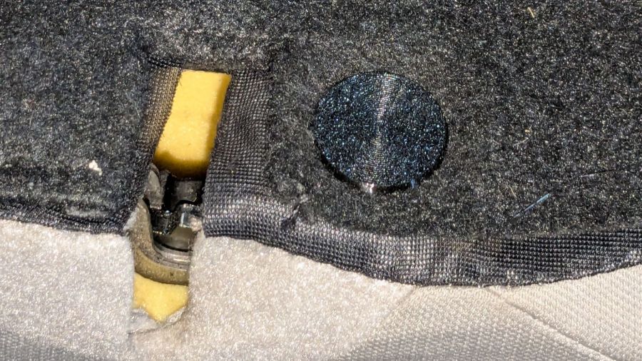
One of the flat-topped pegs anchoring the fuzzy black upholstery / carpet to the back of the rear seats went walkabout a while ago, but the situation only became critical after I vacuumed the crud out of the car.
Living in the future simplifies things:
Upholstery Peg – solid model
Rather than getting all fancy with barbed ends and suchlike, I just slathered the stem with hot-melt glue, jammed it in place, and waited a few breaths:
Upholstery peg – installed
The vivid yellow stuff is seat cushion foam.
3D printing is wonderful for simple parts like that.
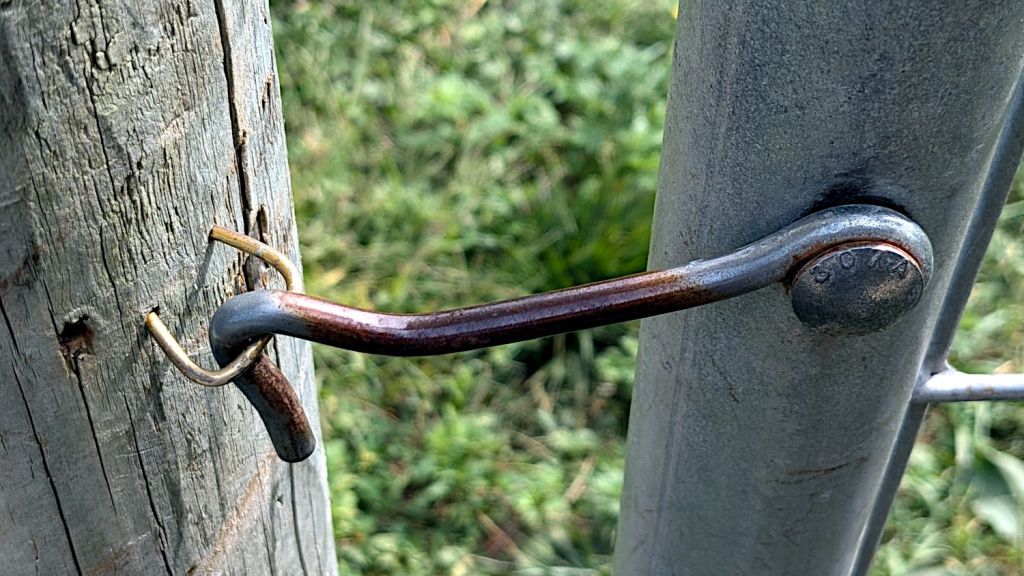
For reasons not relevant here, I ended up making a field-expedient repair to a garden gate latch:
Improvised gate latch staple – installed
The hole in the post just to the left of the obviously improvised staple shows where the Original Staple had vanished, never to be seen again. It looks like the gate has shifted an inch or so to the right (or the post to the left), which would explain why the staple gradually worked loose.
The improvised staple is a length of coat hanger wire bent into a square U, with the ends snipped off at an acute angle:
Improvised gate latch staple – cut wire
Those points do look scary, don’t they?
Then I gently tapped it into place, driving maybe ¾ inch of wire in the wood, flattening the loop a little more than I wanted, but not enough to make me try again.
Not our gate, not Mary’s garden, but deer pose a threat to all veggies within, without regard to ownership.
I have *a lot* of coat hanger wire for repairs like this …
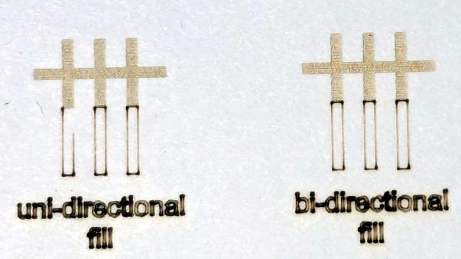
The test patterns will require power / speed tweakage to properly mark cardboard on other machines. The vector boxes are about 1.5 mm wide: these are small differences in small patterns.
The setup for both LightBurn 1.7 RC-13 and RDWorks 8.01.65:
The engraved patterns run at 500 mm/s & 20% power
The lines & letters run at 100 mm/s & 8% Min – 9% Max power
All on white cardboard, with image contrast blown out
Scanning offset = 0.2 mm = the usual setting for my machine
In LightBurn:
Scanning Offset 0.2 – LightBurn
In RDWorks:
Scanning Offset 0.2 – RDWorks
The slight shift to the left in the LightBurn results shows LB does not shift the uni-directional pattern to line up with the vector shape as RDWorks does, which is what started the forum thread.
Scanning offset = 1.0 mm to accentuate the difference, while shredding the bi-direction pattern as expected.
LightBurn’s uni-directional engraved pattern is still in the same slightly leftward-shifted position relative to the vectors, showing the offset value has not been applied:
Scanning Offset 1.0 – LightBurn
RDWorks definitely applies the offset in both modes:
Scanning Offset 1.0 – RDWorks
I do not know why RDWorks did not output the final “l” over there on the right, but it did so on some (not all) of the patterns while setting things up. The jank is strong with it.
So having LightBurn apply the same offset value for both uni- and bi-directional engravings would fix the (slight) offset in my machine. I think it will also fix the much larger misalignment in [the other] machine in that forum discussion.
The whole problem seems to arise from the response time of the HV power supply / laser tube: the position of the left & right edges of the scanned output line depend critically on the rising and falling edges of the current applied to the tube and its power output.
Being me, of course, makes me want a different offset value applied to the uni-directional case, just for fine tuning. Which would require a duplicate offset-per-speed table and that looks like a UX disaster comin’ on strong.


