Ed Nisley's Blog: Shop notes, electronics, firmware, machinery, 3D printing, laser cuttery, and curiosities. Contents: 100% human thinking, 0% AI slop.
The HLP-200B Laser Power Meter Handheld comes fully calibrated at 10.6 μm (CO2). Each laser power meter we calibrate is directly traceable to NIST absolute standards because we use GOLD standards as a reference for each calibration. You will obtain the most accurate result possible
A line in the description says “+/- 3% within the central section”, but that’s not much help. Back in the day, any error percentage referred to the meter’s full-scale value, which would be ±6 W for a 200 W meter.
So I plunked the meter in the middle of the laser platform:
HLP-200B Laser Power Meter – platform center
Then took five measurements at each of ten power levels:
PWM %
10
20
30
40
50
60
70
80
90
99
°C
17.2
17.9
18.4
19.0
19.4
20.3
20.0
20.0
20.5
19.4
Tube Current
3
4
7
10
14
16
18
20
22
24
W
7.1
21.0
42.0
51.8
59.1
63.0
67.8
69.6
74.7
64.0
6.0
19.8
37.2
48.9
52.7
56.0
65.1
69.6
72.4
71.8
6.4
21.1
39.3
45.6
56.5
53.2
61.1
60.7
74.6
75.2
5.6
17.8
37.1
40.4
55.3
53.2
55.1
64.2
74.9
73.5
6.0
17.7
36.9
45.1
54.5
53.1
62.2
69.9
72.2
70.9
Avg Power
6.2
19.5
38.5
46.4
55.6
55.7
62.3
66.8
73.8
71.1
std dev
0.57
1.66
2.19
4.29
2.39
4.26
4.78
4.16
1.34
4.29
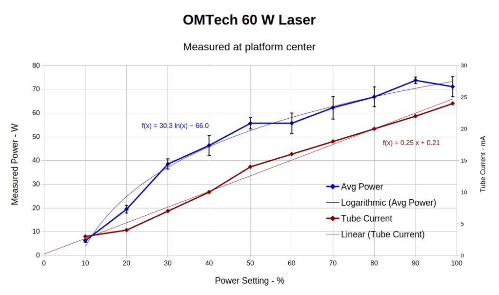
That’s easier to digest from a graph:
HLP-200B Laser Power Meter – 60 W platform center measurements
The absurdity of computing the sample standard deviation from five measurements taken at each power level does not escape me, but this just surveys the situation.
Earlier measurements of the tube current vs. PWM setting, using an RMS value computed by the oscilloscope’s firmware, produced a plot resembling the brown points (read the mA scale on the right) at the high end and differing greatly on the low end. These values come from the power supply’s digital meter, but the straight-line fit doesn’t look absurdly forced and the zero intercept seems plausible. I *assume* it’s actually measuring the tube current, rather than displaying a value computed from the PWM input, but I don’t know for sure.
The rather sketchy paperwork accompanying the laser had one handwritten “21 mA” seemingly corresponding to 60 W output, which looks approximately correct. The instruction manual has a table of power vs. current suggesting that 65-ish W corresponds to 18 mA, with 100 W at 23 mA; it’s unclear whether that is for the 60 W tube in the machine or applies to the entire range of available tubes. The manual recommends not using more than 95% PWM, with which I heartily agree.
Because my meter stand holds the target in the same position relative to the beam during successive measurements much better than I could by hand, I think the pulse-to-pulse variation comes from meter and tube repeatability.
Earlier measurements with a grossly abused Gentec ED-200 joulemeter suggested the laser has some pulse-to-pulse timing variation, down in the millisecond range, but produced roughly the right power for middle-of-the-range PWM settings. This meter integrates the beam power over about ten seconds, so I think variations will be due to (possible) tube power changes and meter repeatability, rather than timing errors.
Obviously, you must not depend on any single-shot measurement to fall within maybe 10% or several watts of the right answer.
With all that in mind and assuming the meter is delivering approximately the right numbers on average, the power supply overcooks the tube at any PWM setting above 50%. I’ve noticed some beam instability / defocusing over 80% while cutting recalcitrant materials, which is surely due to the tube not lasing properly. I generally avoid doing that.
The log fit to the measured power looks better than I expected, although I’m unprepared to compute natural logs in my head.
PrusaSlicer V 2.9.0 for Linux arrives as a Flatpak, instead of the previous AppImage, which wouldn’t matter except that the Flatpak sandbox prohibits access to anything outside each user’s home directory. I long ago set up access to the fileserver in the basement through filesystems mounted on /mnt, which is now inaccessible.
Overall, 2.9.0 seems significantly more sluggish and uglier than the 2.8.x series, but at least Prusa still supports Linux.
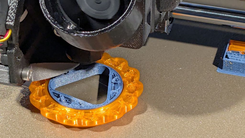
Just to show PrusaSlicer can fetch files from the server and to have some pictures enhancing this post’s negligible SEO, I built a couple of Gear Fidget Toys:
Double Gear fidget toy – on platform
Which pop off the platform ready to roll:
Double Gear fidget toy – finished
A trace of silicone grease eased between the pieces on a slip of paper makes the spinning action so smooth.
As usual, the multi-material version takes twice as long to build due to all the filament swapping. I think I must improve the MMU3’s spoolholders, because the MMU3 (very) occasionally fails to ram the filament into the extruder, seemingly due to the force required to pull filament from the recalcitrant spools.
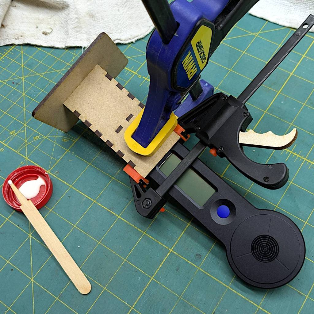
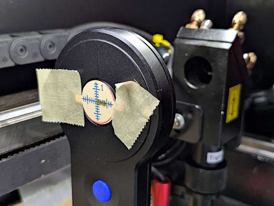
The overall measurement process for the HLP-200B laser power meter requires more coordination than I can muster on a dependable basis, so a third hand seemed in order:
HLP-200B Power Meter – target setup
In actual use, a pair of finger-crushingly strong magnets laid on the base hold it firmly to the honeycomb.
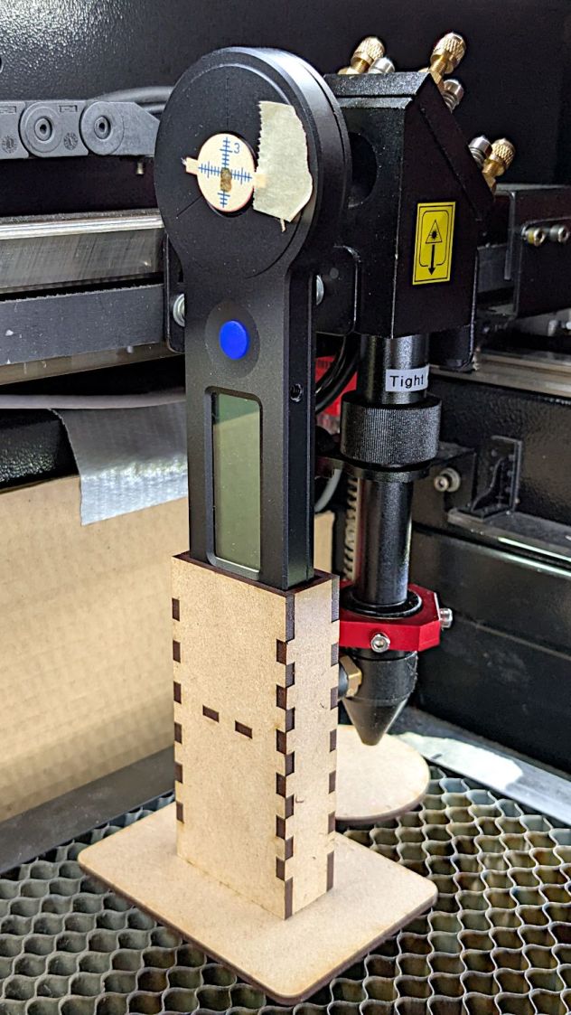
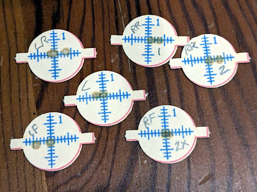
Because a CO₂ laser beam is invisible, the only way to know where it hits is to char a bit of paper:
HLP-200B Power Meter – target detail
With that evidence, I can jog the platform up-and-down and the gantry front-and-back to center the beam on the paper target and, thus, on the sensor behind it. That process happens at each test position across the platform:
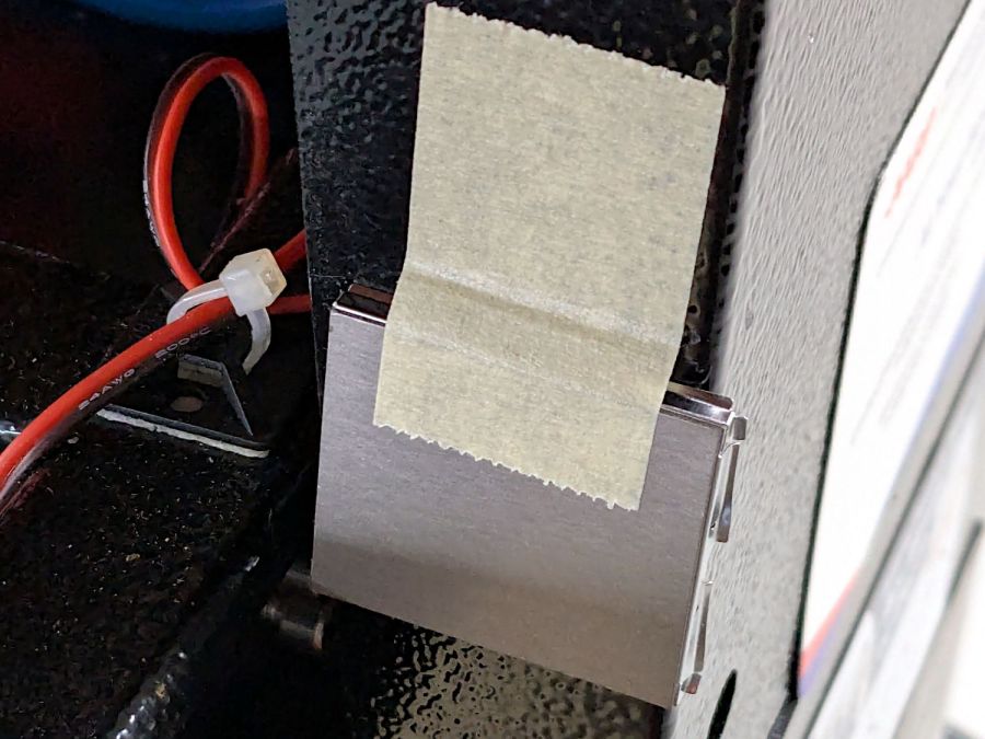
Rather than install a switch to bypass the interlock, I taped a steel cover harvested from defunct electronics over the sensor:
Laser lid interlock sensor – bypassed
Which has the useful side effect of preventing me from closing the lid with the interlock defeated.
The holder is just slightly larger than the meter’s handle and some clamps produced a snug fit while the glue cured:
HLP-200B Power Meter – holder gluing
The holder keeps the meter sensor at the same position vertically and within about a millimeter horizontally. The laser beam seems to be around 5 mm in diameter (the scorches above come from the hottest central part), so the beam should hit the same position on the sensor during successive measurements, making them far more repeatable than my waving it around by hand.
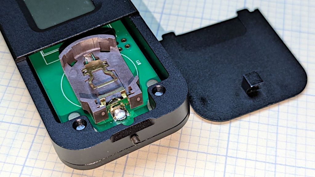
The manual does not exactly match the hardware. In particular, “so users won’t need any tools to replace the battery” is incorrect:
HLP-200B – battery lid screw
Until you loosen the M2 setscrew below the finger notch a couple of turns, “Use just fingers to remove the battery cover” will merely scuff your fingerprints. Apply a 1.5 mm or 1/16 inch straight screwdriver bit with no more than finger torque and, after two or three turns, the lid comes free.
The meter arrives without a battery, so you passed the first test.
Despite the “another screw hold (M4) is added”, there’s only one tapped hole in the case, as visible in the back panel photo. Seen from the front, it’s above the four digit LCD.
Operation is at best awkward and at worst hazardous:
Press the blue button to turn it on and hear a beep
It’s ready to measure within three seconds
Hit it with the laser beam until it beeps
The LCD shows the power for six seconds
It shuts off with a beep
Bonus: If the meter doesn’t detect any energy, it shuts off 20-ish seconds after the button press
Minus my power ears, the beeps are completely inaudible.
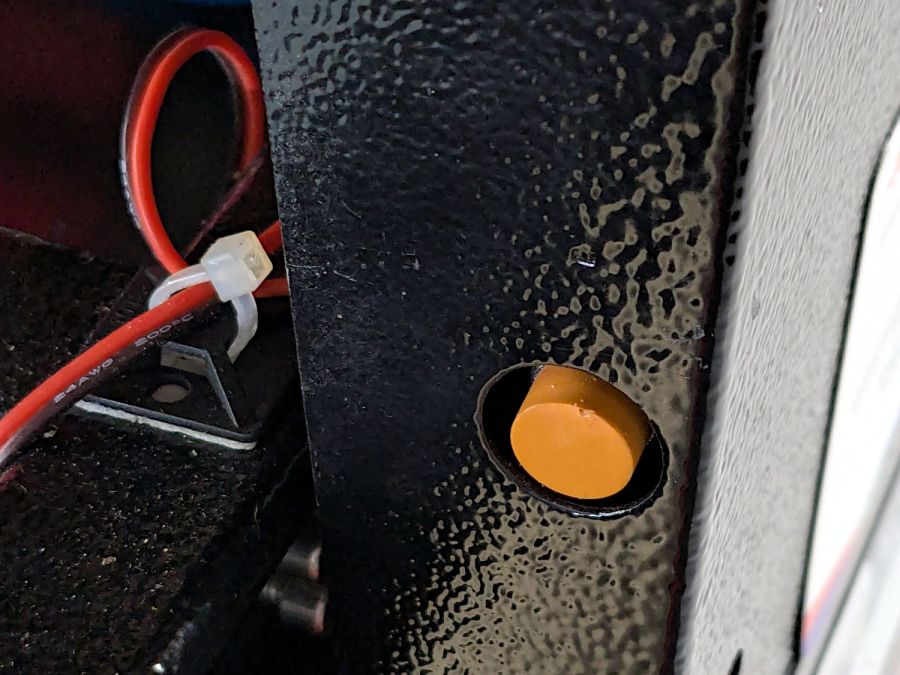
The meter is sensitive enough to respond to weak heat sources like LED bulbs and even fingertips, so you can test it without firing the laser. The numeric value shows the power from a CO₂ laser beam dumping an equivalent amount of energy into the sensor:
HLP-200B – finger heat response
The sensor target is 20 mm OD, although the instructions remind you to “Ensure the laser is emitted to the center of the sensor”. I suspect hitting the sensor with a focused laser spot will eventually damage the surface.
Making a real measurement requires:
Set the Pulse button for continuous output
Set the power level
Defeat the lid interlock switch on the laser cabinet
Push the blue button on the HLP-200B
Quickly position the meter target accurately in the beam path
Hold down the laser Pulse button
Freeze in that position until the meter beeps
Release the Pulse button
Quickly reorient the meter and read the display
I have a visceral reluctance concerning safety interlock overrides, misgivings about poking my head inside the cabinet, and no yearning to put one hand near the beam line with the other on the console. Yes, I have known-good laser safety glasses.
The meter generates plausible results for the (claimed) 60 W tube in my machine, but further tests await conjuring fixtures to keep various irreplaceable body parts out of harm’s way.
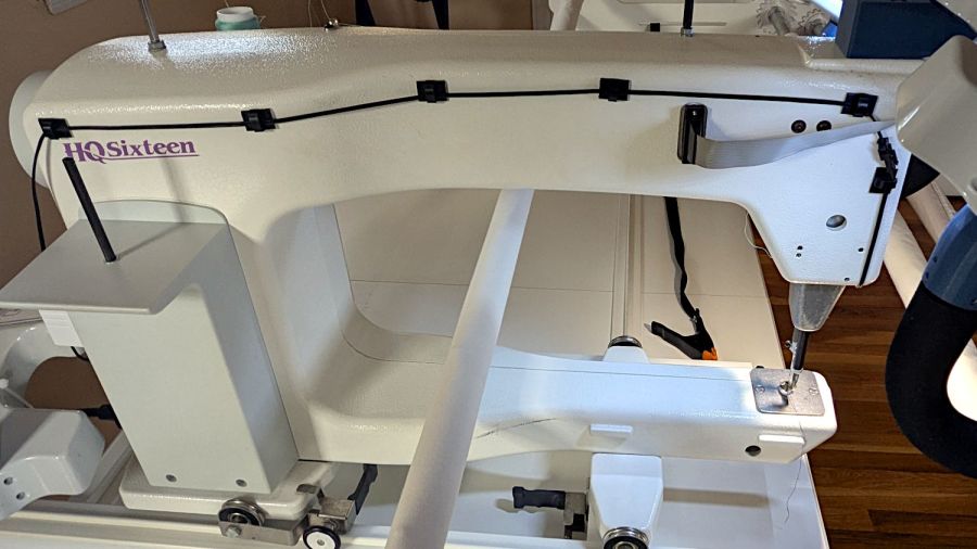
Mary’s Handi-Quilter HQ Sixteen is new-to-her, but it’s had two previous owners over the past two decades. Neither of them reported any particular problems with it, but it now displays an intermittent Motor Stall error on its LCD panel(s). This post summarizes what I know and guesstimate to date.
The Motor Stall error happens at the first motor motion after turning the machine on, upon pressing either the Needle Up/Down or Start/Stop button on the handlebars. The motor does not move at all during the slight pause between pushing the button and seeing the error message. Pressing either button again clears the error message, although I (obviously) do not know if doing so affects any of the microcontroller’s internal status flags; the error dependably reoccurs after doing so.
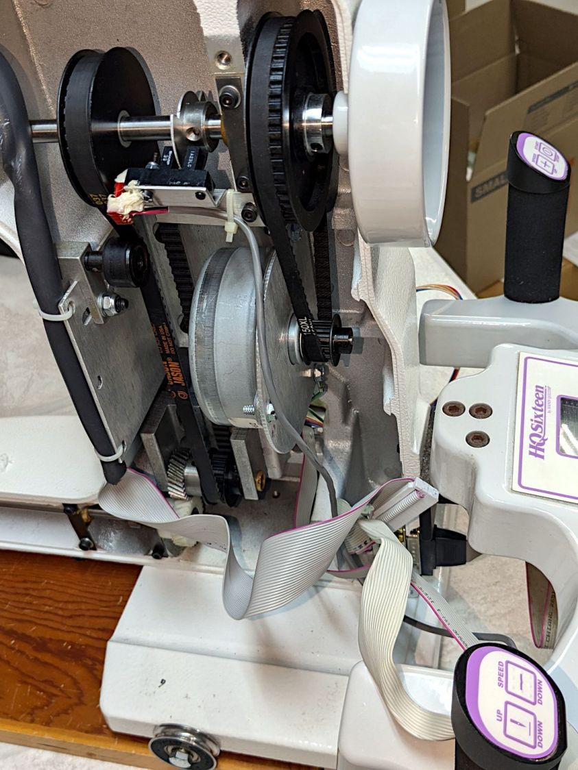
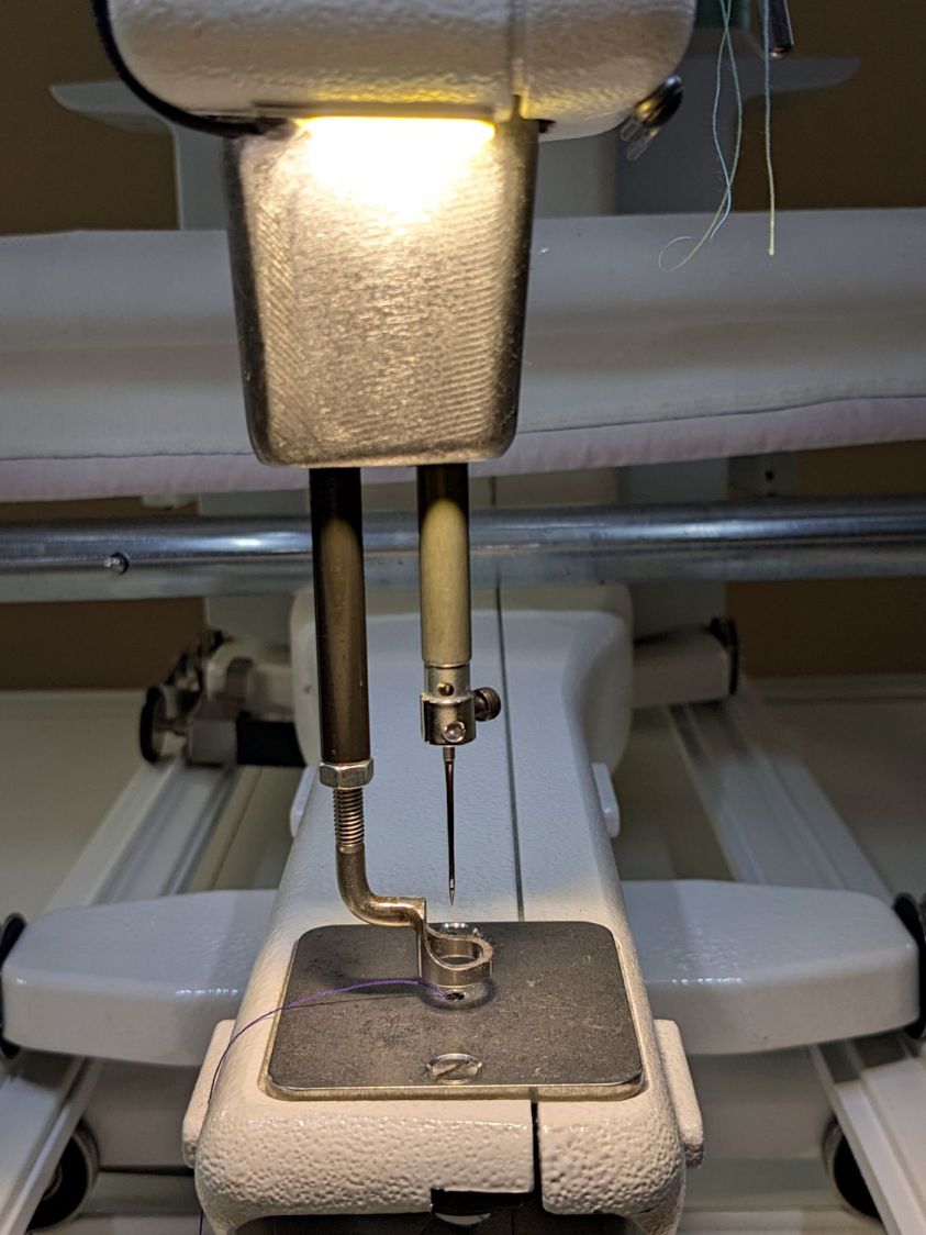
A separate sector disk on the machine’s shaft sets the needle-up and needle-down positions through an optointerrupter:
The white silicone snot on the interrupter connector is original.
After the error occurs, slowly turning the machine handwheel while pressing either button generally prevents the error message from reappearing, suggesting the “stalled” signal from the motor is working and the signal reaches the microcontroller.
Turning the handwheel while pressing the Up/Down button does not produce an error message due to the “motor” not stopping at the appropriate edge of the sector disk.
The InterWebs suggest a thread jam, crud in the bobbin, and a needle crash can trigger a Motor Stall. When the machine is operating correctly, running it at slow speed and stopping the handwheel by hand (it has little torque) triggers the Motor Stall error message. However, the controller will clear the message and the machine will resume normal operation thereafter.
Conversely, when the Motor Stall error occurs at startup, it remains absolutely consistent and survives the usual “Reboot that sucker!” power cycle. Leaving the machine turned off and untouched for a few hours / overnight may reset whatever is wrong, after which it will run normally through many power cycles.
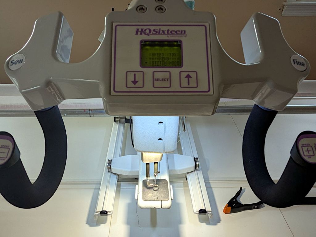
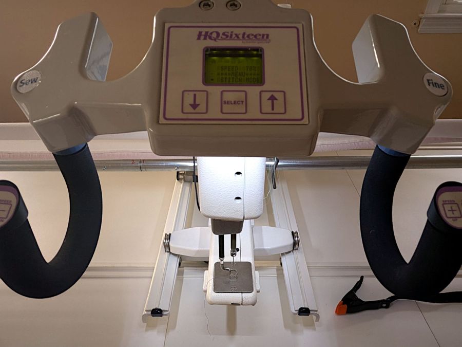
Long enough, indeed, to finish an entire practice quilt over the course of several days:
HQ Sixteen – remounted handlebars in use
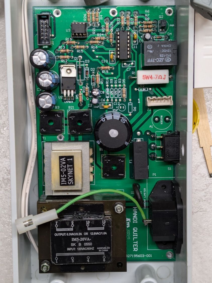
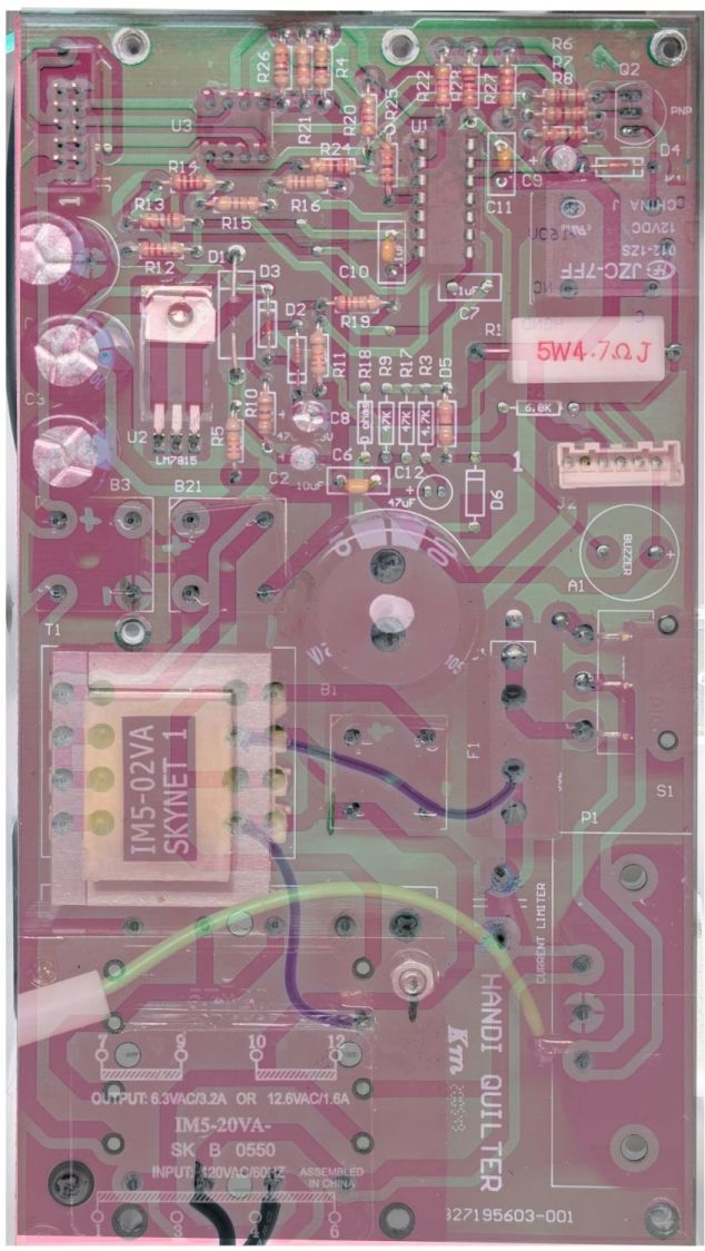
The component side of the power supply / motor interface PCB inside the pod:
Power PCB – components
Connections:
Microcontroller board at top left
BLDC shaft motor middle right
Frame ground on green wire
AC power input on the IEC jack
Power switch just above IEC jack
A closer view of the ICs:
Power PCB – IC detail
Some initial thoughts on the circuitry, without detailed PCB tracing …
Although the date codes suggest it was built in 2005, the electrolytic caps show no signs of The Plague.
The TO-220 package is a classic LM7815 regulator with its tab soldered to a copper pad. No extensive copper pour on either side serves as a heat spreader.
The 8 pin DIP is an MCT62 dual optoisolator handling the motor speed control and stall sense feedback.
The big transformer at the bottom sends raw DC to the microcontroller board through B3 and J1, filtered by two of the electrolytic caps along the left edge. I think the low side remains isolated from the power board’s common, thus isolating the microcontroller from the AC power line.
The Skynet (‽‽) transformer produces +15 V through the 7815 regulator and B21 bridge, filtered by the middle electrolytic cap along the left edge of the board. All of the circuitry on the board uses that supply, with the low side as circuit common.
The 160 VDC (!) supply for the BLDC motor comes directly from the AC power line with no isolation through the Current Limiter PTC, the B1 bridge, and the hulking electrolytic cap in the middle of the board. The relay in the upper right energizes just after the power goes on, connecting the motor power return lead to circuit common through the 5W 4.7Ω sandbox resistor. The “common” side of B1 is, thus, not connected to the neutral side of the power line and, more importantly, none of the circuitry on the PCB is isolated from the power line.
As a result, casually clipping a line-powered oscilloscope’s “ground” probe lead to what’s obviously the circuit “common” will, in the best case, turn the ground lead into a fuse. I’ve done this exactly once, deep in the past, with a Tektronix 7904 mainframe oscilloscope priced (with plugins) somewhat higher than the house we owned at the time; suffice it to say I learned from that mistake.
I think (part of) the LM339 quad comparator determines the relay’s time delay, perhaps in response to a signal from the microcontroller after it wakes up.
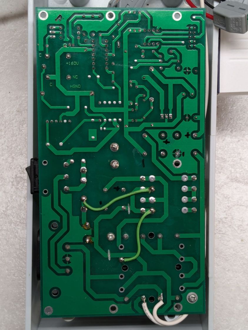
The solder side of the same board:
Power PCB – solder
The two green wires and trace cuts are original, apparently to power just B21 (the motor supply) from the AC line through the fuse + PTC, with the two transformers connected directly to the AC line through the switch & fuse. The two white wires on the bottom go to the power supply I added for the Chin Light; the Motor Stall problem predates that modification and the handlebar relocation.
After cleanup / squaring / tweaking, the two images combine into an X-ray view:
Power PCB – overlaid
With all that in mind, some possible causes …
Taking the power supply and microcontroller pods off the machine and poking all the obvious spots has no effect. Not taking them off and not touching the machine may resolve the problem by the next day, after having it fail consistently during most of the previous day.
The motor label says DR-8538-937, which does not appear anywhere online, so this must be a unique Handi-quilter part. An overview of DR-8538 motors suggests they’re available with a variety of windings, none of which match the machine’s 160 VDC supply voltage. Because the PCB has no high-voltage / high-current switching components, other than the bulk DC supply, the motor contains the BLDC control & drive circuitry. The closest matching catalog page conspicuously does not identify the motor wiring connections.
This figure from another catalog suggests the motor accepts a DC speed control and outputs an open-collector “locked rotor” signal:
BLDC DR-8538-555 Motor pinout
The Handi-Quilter DR-8538-937 motor has five leads in the J2six pin header which could match thusly to the four pins in the figure:
Pin 1 = 160 VDC (pin 1 → 24 VDC )
Pin 2 = missing
Pin 3 = common (pin 2 → GND)
Pin 4 = ? (pin 3 → -On)
Pin 5 = ? (pin 4 → Lock ?)
Pin 6 = +Buzzer and elsewhere (?)
This will obviously require reverse engineering the schematic from the PCB traces, thus the X-ray view above.
The most obvious cause of a Motor Stall would be a defective / failing motor. Through a cosmic coincidence, a motor “removed from a working HQ Sixteen” was available on eBay when I looked. It behaves no differently than the original motor and, while it’s possible both motors have the same internal fault, that seems unlikely. The “new” motor now runs the machine, with the original motor neatly bagged in a box against future need.
Re-seating all the ICs on both boards produced ominous crunching sounds, but no improvement. Wiping DeoxIT on the leads of the two ICs on the power board had no effect.
Replacing the 10-conductor ribbon cable between the two boards had no effect. I knew I was saving those insulation displacement connectors for a good reason.
The MCT62 optoisolator has a minimum current transfer ratio of 100% at 10 mA diode current. A gimmicked test setup produced 8 mA in the output transistors with 6 mA through the diodes, which seems good enough.
The relay clicks audibly, even with my deflicted ears, suggesting that it’s working, although we have not had a motor failure while we were listening. It is possible the contacts are intermittent, letting the relay click without making contact; we’re now listening intently.
The machine lives upstairs, my instruments live in the basement, and I am unwilling to lug an awkward and invaluable 50 pound lump between the two. The next time the motor stalls, I must dismount the power pod from the side of the machine, haul a bunch of gear (including an isolation transformer!) upstairs, and probe various points while it remains defunct.
Things to find out:
What each of the five motor wires do
Discover the circuitry handling the optoisolator signals
What drives the relay?
Even though the machine ran perfectly for a week, a fundamental Debugging Rule applies: If you didn’t fix it, it ain’t fixed.
You’ve just seen more tech info on the HQ Sixteen than previously existed on The InterWebs.
The light comes from a small chip-on-board LED affixed under the chin of the machine arm with heatsink tape:
HQ Sixteen Chin Light – detail
Yes, the pool of warm white COB LED light clashes horribly with the cool white 5 mm LEDs lighting the background (not to mention wintry daylight from the windows), but it’s sufficiently OK.
I intended to run the wiring inside the machine arm, but all the pre-existing holes I wanted to use were oiling access points or blocked by whirling shafts inside, so the wire runs along the outside:
HQ Sixteen Chin Light – wiring
The Handi-Quilter control & lighting goes through the bare gray ribbon cable to the handlebars, so I’m not too far down the stylin’ scale. The next version of the machine has round external cables, but this machine is what it is.
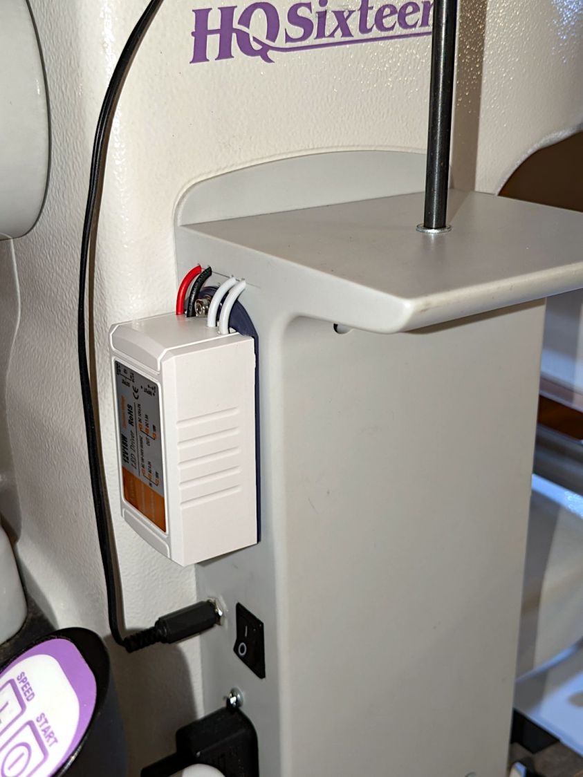
I mounted the 12 VDC supply to the back panel of the machine’s power box with five 3 mm holes:
HQ Sixteen Chin Light – power supply
A bag of right-angle barrel connectors will arrive shortly.
The exposed wiring at the top (the white wires carry switched 120 VAC from the PCB inside the box) seemed … unaesthetic, so I conjured a cover from the vasty digital deep:
Power Supply Cover – solid model
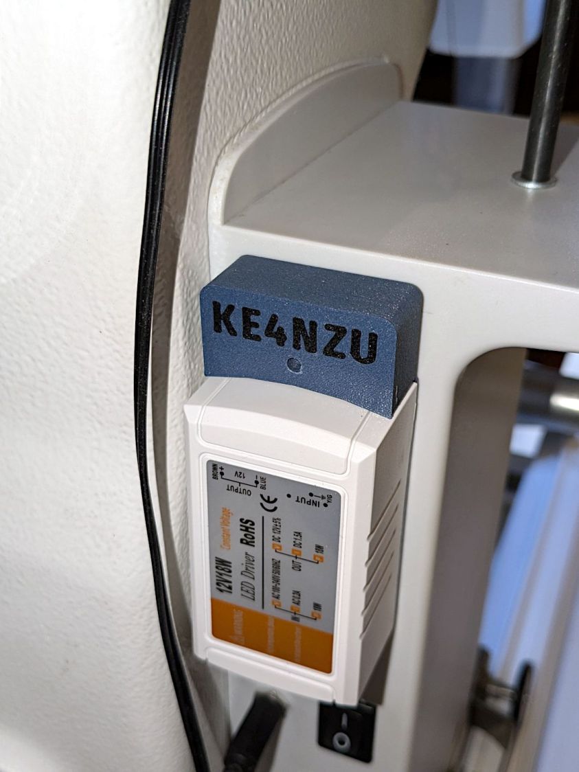
Which fit neatly into place on the first try:
HQ Sixteen Chin Light – supply cover fit test
That’s a trial fit, because I am not pulling the machine apart again until there’s more work to do inside.
The blurry rocker switch below the Chin Light supply controls the machine power: turn it on and everything lights up as it should.
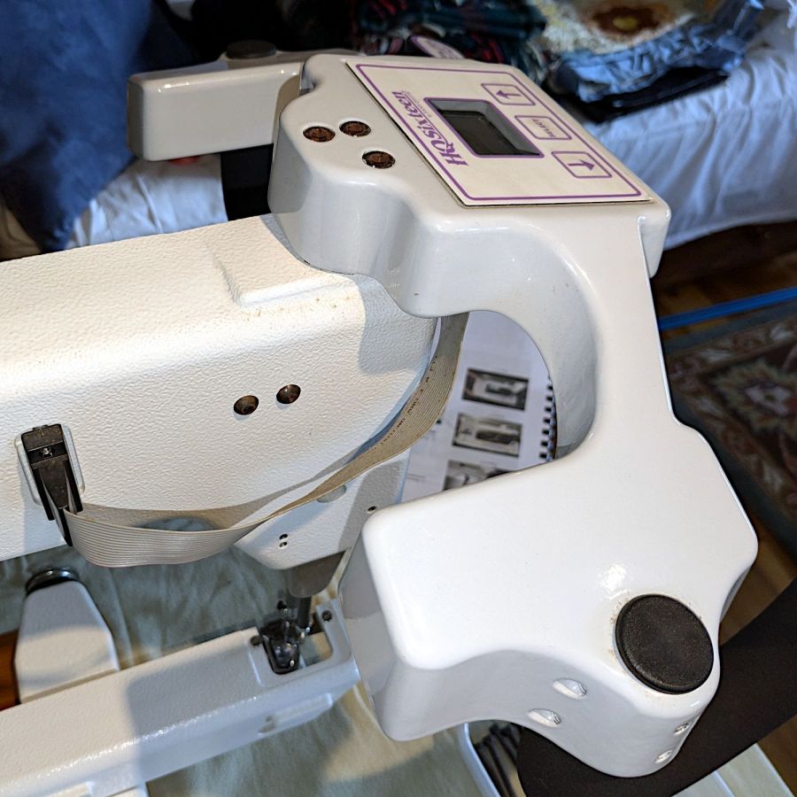
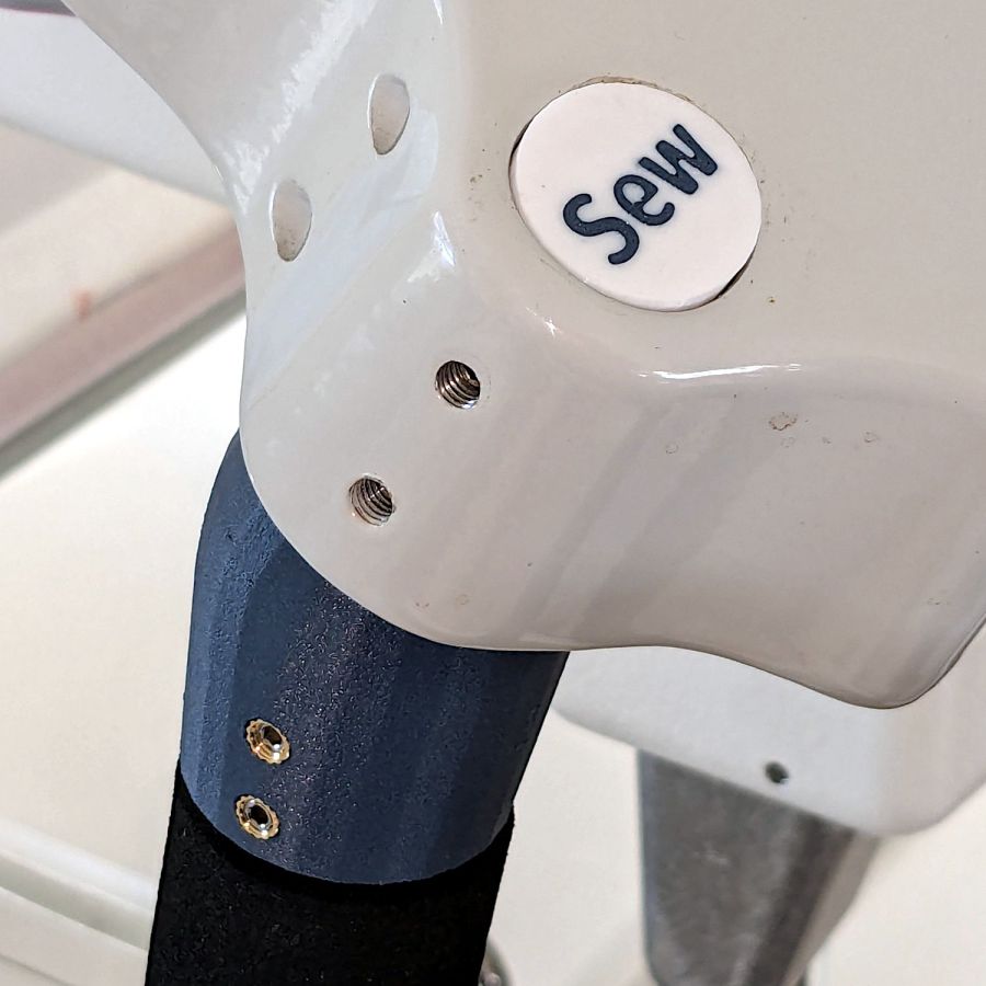
The stock Handi-Quilter HQ Sixteen has serviceable black rubber caps covering the holes for the grips:
HQ Sixteen – original front handlebar mount
Because we live in the future, I can do better than that:
HQ Sixteen – grip cap left
In truth, the plastic grip plug now sticks up into the hole just beyond the top setscrews, leaving not enough room for the black plugs, so I had to make new covers.
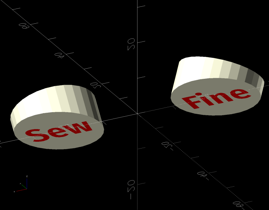
They’re a multi-material print using white PETG to kinda-sorta match the machine and blue PETG-CF to match the other plastic parts. The colors in the solid model just distinguish the two materials:
Handlebar Grip Mount – plug caps – solid model
The white covers have recesses exactly fitting the text:
Handlebar Grip Mount – cap text recess – solid model
In some cases that’s not needed, but I’m unsure how PrusaSlicer knows what I intend and chopping the text out was easy, so that’s how I did it.
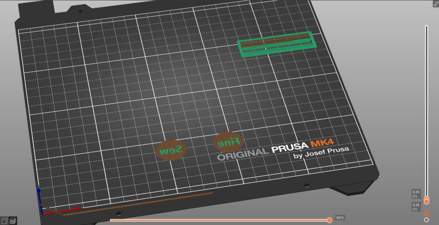
I did not realize applying a transformation, like translate() or BOSL2’s syntactic sugar left(), to both the cover and the text implicitly joins them into a single “object”, so the slicer can’t distinguish them as separate materials. As a result, the OpenSCAD code must move the pieces separately:
Export the model as a 3mf file, import it into PrusaSlicer, and you get separate objects for the cover and the text. Assign different materials and slice to produce a multi-material result, with the Wipe Tower in the background:
Handlebar Grip Mount – cap first layer – PrusaSlicer
They must print face down to merge the two colors into a single flat surface with a nubbly texture from the steel sheet’s coating.
Disks of adhesive sheet will eventually stick them atop the plugs, but for now they’re just dropped into the holes.
This file contains hidden or bidirectional Unicode text that may be interpreted or compiled differently than what appears below. To review, open the file in an editor that reveals hidden Unicode characters.
Learn more about bidirectional Unicode characters


