Mary is at least the third owner of a steel rack, originally intended to hold packages of retail stuff, which now holds (much of) her collection of quilting rulers:

Obviously, it was never intended to hold heavy acrylic sheets, but it worked surprisingly well, right up to the point where too many of the rulers collected on two adjacent columns of pegs and overbalanced the whole affair atop her while she attempted to remove a ruler.
Subsequent accident recreation showed the rack toppled when the weight of the rulers on the two adjacent columns of hooks moved the center of mass outward, just inside the line between those feet, whereupon the slightest tug on a ruler pulled it over.
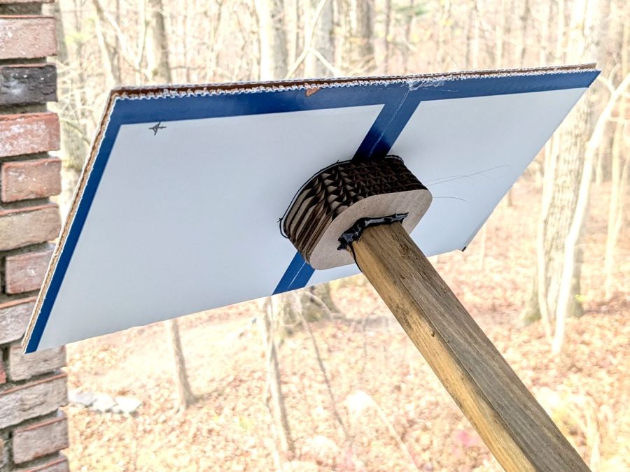
Measurements revealed the four legs do not sit on a square contact patch, are not parallel to the radii from the center point, and are not uniformly distant from the center. Rather than committing to a finished product, I made a cardboard prototype to verify a bigger base would solve the problem and I could capture all those feet.
You don’t have such a rack, so the exact dimensions don’t matter, but the LightBurn layout looks like this:

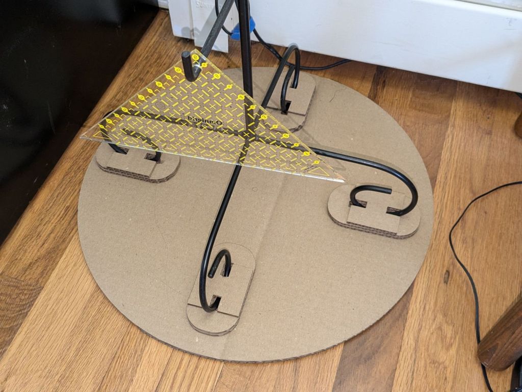
The disk is two cross-laid sheets for stiffness, with marks burned on the top to help align the feet more-or-less around the center point.
The oblong rings fit around the feet to capture them, so cut eight or twelve to make four stacks a bit taller than the wire diameter.
The H shape then glues atop the rings to hold the feet in place. They’re not removable, but a razor knife will eventually solve that problem.
I slobbered hot melt glue across the cardboard disks to hold them together, glued and aligned the rings where the feet dented the disks, stood the rack in the rings, and glued the H plates.
About an hour elapsed from the sound of the crash to the rack once again standing quietly beside the fabric cabinets.
We’ll run this for a while and eventually replace it with a plywood disk and screwed-in-place clamps for the feet, which will surely call for wood surface preparation / stain / seal treatment.