The Smell of Molten Projects in the Morning

Ed Nisley's Blog: Shop notes, electronics, firmware, machinery, 3D printing, laser cuttery, and curiosities. Contents: 100% human thinking, 0% AI slop.

Author: Ed

  • Changing the Case of a FAT File Name

    While converting a stop-action series of images from the HDR-AS30V into a movie, I wanted change all the image files on a USB Flash drive from DSC00008.JPG to dsc00008.jpg, so as to simplify typing their names.

    Alas, because the camera’s exFAT filesystem cares not one whit about case, the obvious command doesn’t work:

    rename 's/JPG/jpg/' /mnt/part/*
    /mnt/part/DSC00008.JPG not renamed: /mnt/part/DSC00008.jpg already exists
    

    So you must do each piece in two steps:

    rename 's/JPG/jpgx/' /mnt/part/*
    rename 's/jpgx/jpg/' /mnt/part/*
    rename 's/DSC/dscx/' /mnt/part/*
    rename 's/dscx/dsc/' /mnt/part/*
    

    Obvious once you see it, I suppose…

    See the comments for a better way:

    rename 'y/A-Z/a-z/' *JPG
    
  • Sony NP-BX1 Battery Test Fixture

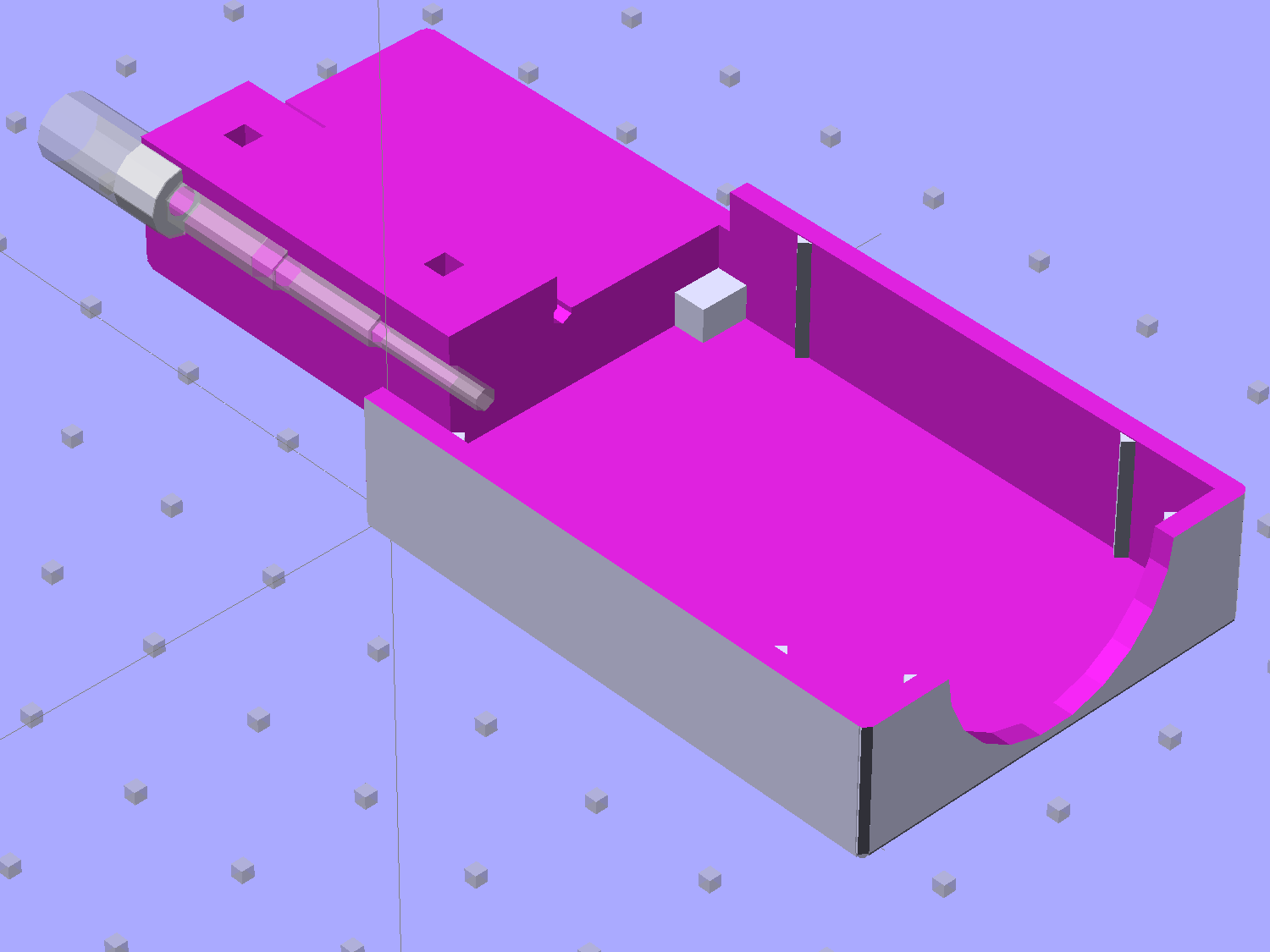
    The Sony HDR-AS30V “action camera” uses NP-BX1 lithium batteries (3.7 V @ 1.24 A·h = 4.6 W·h) that are, of course, a completely different size and shape than any other lithium battery on the planet.

    So.

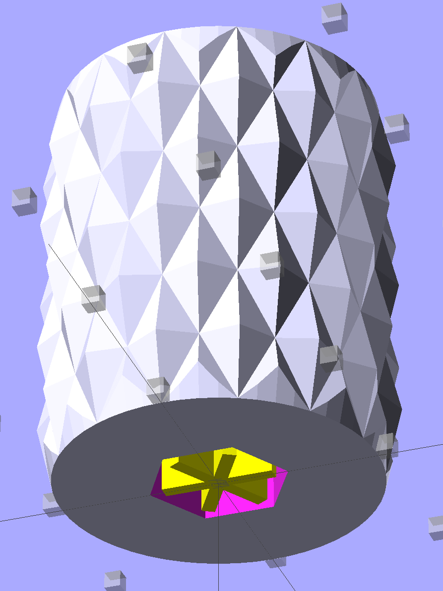
    Tweaking a few dimensions in the Canon NB-6L source code, tinkering with the layout of the contact pins, and shazam Yet Another 3D Printed Battery Test Fixture:

    NP-BX1 Holder - show layout
    NP-BX1 Holder – show layout

    It builds nicely, although the contact pin tunnels are a bit too close to the top of the case:

    Sony NP-BX1 Holder - on platform
    Sony NP-BX1 Holder – on platform

    After reaming out the contact pin holes to the proper diameters & depths, then gluing the plugs in place, it works just as you’d expect:

    Sony NP-BX1 battery holder
    Sony NP-BX1 battery holder

    It’s worth noting that the Wasabi charger accepts the batteries upside-down, with the conspicuous chevron against the charger body. It’s definitely not the way all the other chargers work. The keying recesses on the battery (corresponding to the blocks in the solid model) lie along the bottom edge of the contact surface, so flipping the battery over means they’ll hold it in place, but … oh, well.

    That grotty Powerpole connector last saw use in some random benchtop lashup. At some point I’ll be forced to start making more of those.

    The OpenSCAD source code:

    // Holder for Sony NP-BX1 Li-Ion battery
    // Ed Nisley KE4ZNU January 2013
    
    include <MCAD/boxes.scad>
    
    // Layout options
    
    Layout = "Show";					//  Show Build Fit Case Lid Pins Plugs AlignPins
    
    //- Extrusion parameters - must match reality!
    //  Print with +2 shells and 3 solid layers
    
    ThreadThick = 0.20;
    ThreadWidth = 0.40;
    
    HoleWindage = 0.2;
    
    function IntegerMultiple(Size,Unit) = Unit * ceil(Size / Unit);
    
    Protrusion = 0.1;			// make holes end cleanly
    
    inch = 25.4;
    
    BuildOffset = 3.0;			// clearance for build layout
    
    Gap = 8.0;					// separation for Fit parts
    
    //- Battery dimensions - rationalized from several samples
    //  Coordinate origin at battery corner by contact plates on bottom surface
    
    BatteryLength = 43.0;
    BatteryWidth = 30.0;
    BatteryThick =  9.5;
    
    ContactWidth = 2.90;
    ContactLength = 4.30;
    ContactRecess = 0.90;
    
    ContactOC = 10.0;			// center-to-center across contact face
    ContactOffset = 6.20;		// offset from battery edge
    ContactHeight = 6.30;		// offset from battery bottom plane
    
    AlignThick = 2.75;			// alignment recesses on contact face
    AlignDepth = 1.70;			// into face
    AlignWidth1 = 3.70;			// across face at contacts
    AlignWidth2 = 3.60;			//  ... other edge
    
    //- Pin dimensions
    
    PinTipDia = 1.6;
    PinTipLength = 10.0;
    
    PinTaperLength = 2.3;
    
    PinShaftDia = 2.4;
    PinShaftLength = 6.8;
    
    PinFerruleDia = 3.1;
    PinFerruleLength = 2.0;
    
    PinLength = PinTipLength + PinTaperLength + PinShaftLength + PinFerruleLength;
    
    ExtendRelax = 1.5 + ContactRecess;		// pin extension when no battery is present
    ExtendOvertravel = 1.0;					//  ... beyond engaged position
    
    //- Spring dimensions
    
    SpringDia = 3.1;						// coil OD
    SpringMax = 9.3;
    SpringLength = SpringMax - 0.5;			// slightly compressed
    SpringMin = 4.5;
    
    SpringPlugOD = IntegerMultiple(5.0,ThreadWidth);		// plug retaining the spring
    SpringPlugID = 2.0;
    SpringPlugLength = IntegerMultiple(4.0,ThreadWidth);
    SpringPlugSides = 3*4;
    
    SpringTravel = ExtendRelax + ExtendOvertravel;
    
    //- Holder dimensions
    
    GuideRadius = ThreadWidth;			// friction fit ridges
    GuideOffset = 7;					// from compartment corners
    WallThick = 4*ThreadWidth;			// holder sidewalls
    
    BaseThick = 6*ThreadThick;			// bottom of holder to bottom of battery
    TopThick = 6*ThreadThick;			// top of battery to top of holder
    
    ThumbRadius = 10.0;			// thumb opening at end of battery
    
    CornerRadius = 3*ThreadThick;			// nice corner rounding
    
    CaseLength = SpringPlugLength + SpringLength + PinLength - ExtendRelax
    			+ BatteryLength + GuideRadius + WallThick;
    CaseWidth = 2*WallThick + 2*GuideRadius + BatteryWidth;
    CaseThick = BaseThick + BatteryThick + TopThick;
    
    AlignPinOD = 1.75;			// lid alignment pins - filament snippets
    AlignPinLength = 5.0;
    AlignPinInset = 7.0;
    AlignPinOffset = -3.75;		//  from centerline - choose to miss contact pins
    
    //- XY origin at front left battery corner, Z on platform below that
    
    CaseLengthOffset = -(SpringPlugLength + SpringLength + PinLength - ExtendRelax);
    CaseWidthOffset = -(WallThick + GuideRadius);
    CaseThickOffset = BaseThick;
    
    LidLength = ExtendRelax - CaseLengthOffset;
    
    echo(str("Contact pin tip dia: ",PinTipDia));
    echo(str("Drill depth to taper end: ",
    		 (SpringPlugLength + SpringLength + PinFerruleLength + PinShaftLength + PinTaperLength),
    		 " -- Dia: ",PinShaftDia));
    echo(str("            to ferrule end: ",
    		  (SpringPlugLength + SpringLength + PinFerruleLength),
    		 " -- Dia: ",PinFerruleDia));
    echo(str("            to plug end: ",SpringPlugLength,
    		 " -- Dia: ",SpringPlugOD));
    
    //----------------------
    // Useful routines
    
    module PolyCyl(Dia,Height,ForceSides=0) {			// based on nophead's polyholes
    
      Sides = (ForceSides != 0) ? ForceSides : (ceil(Dia) + 2);
    
      FixDia = Dia / cos(180/Sides);
    
      cylinder(r=(FixDia + HoleWindage)/2,
               h=Height,
    	   $fn=Sides);
    }
    
    module ShowPegGrid(Space = 10.0,Size = 1.0) {
    
      Range = floor(50 / Space);
    
    	for (x=[-Range:Range])
    	  for (y=[-Range:Range])
    		translate([x*Space,y*Space,Size/2])
    		  %cube(Size,center=true);
    
    }
    
    //-------------------
    
    //-- Guides for tighter friction fit
    
    module Guides() {
      	  translate([GuideOffset,-GuideRadius,CaseThickOffset])
    		PolyCyl(2*GuideRadius,(BatteryThick - Protrusion),4);
    	  translate([GuideOffset,(BatteryWidth + GuideRadius),CaseThickOffset])
    		PolyCyl(2*GuideRadius,(BatteryThick - Protrusion),4);
    	  translate([(BatteryLength - GuideOffset),-GuideRadius,CaseThickOffset])
    		PolyCyl(2*GuideRadius,(BatteryThick - Protrusion),4);
    	  translate([(BatteryLength - GuideOffset),(BatteryWidth + GuideRadius),CaseThickOffset])
    		PolyCyl(2*GuideRadius,(BatteryThick - Protrusion),4);
    	  translate([(BatteryLength + GuideRadius),GuideOffset/2,CaseThickOffset])
    		PolyCyl(2*GuideRadius,(BatteryThick - Protrusion),4);
    	  translate([(BatteryLength + GuideRadius),(BatteryWidth - GuideOffset/2),CaseThickOffset])
    		PolyCyl(2*GuideRadius,(BatteryThick - Protrusion),4);
    
    }
    
    //-- Contact pins (holes therefore)
    
    module PinShape() {
    
      union() {
    	cylinder(r=(PinTipDia + HoleWindage)/2,h=(PinTipLength + Protrusion),$fn=6);
    
    	translate([0,0,PinTipLength])
    	  cylinder(r=(PinShaftDia + HoleWindage)/2,
    			   h=(PinTaperLength + PinShaftLength + Protrusion),$fn=6);
    
    	translate([0,0,(PinLength - PinFerruleLength)])
    	  cylinder(r=(PinFerruleDia + HoleWindage)/2,
    				h=(PinFerruleLength + Protrusion),$fn=6);
    
    	translate([0,0,(PinLength)])
    	  cylinder(r=(SpringDia + HoleWindage)/2,
    				h=(SpringLength + Protrusion),$fn=6);
    
    	translate([0,0,(PinLength + SpringLength - HoleWindage)])	// windage for hole length
    	  cylinder(r=(SpringPlugOD + HoleWindage)/2,h=3*SpringPlugLength,$fn=SpringPlugSides);
    
    //	  translate([0,0,(PinLength + SpringLength + SpringPlugLength)])
    //	  cylinder(r=(SpringPlugOD + HoleWindage)/2,h=2*SpringPlugLength,$fn=SpringPlugSides);	// extend hole
      }
    
    }
    
    module PinAssembly() {
    
      translate([ExtendRelax,ContactOffset,CaseThickOffset + ContactHeight]) {
    	rotate([0,270,0]) {
    	  PinShape();												// pins
    	  translate([0,(1*ContactOC),0])
    		PinShape();
    	}
      }
    
    }
    
    //-- Alignment pins
    
    module AlignPins() {
    
    	for (x=[-1,1])
    		translate([x*(LidLength - 2*AlignPinInset)/2,AlignPinOffset,0])
    			rotate(45)
    			PolyCyl(AlignPinOD,AlignPinLength);
    }
    
    //-- Case with origin at battery corner
    
    module Case() {
    
      difference() {
    
    	union() {
    
    	  difference() {
    		translate([(CaseLength/2 + CaseLengthOffset),
    				  (CaseWidth/2 + CaseWidthOffset),
    				  (CaseThick/2)])
    		  roundedBox([CaseLength,CaseWidth,CaseThick],CornerRadius); 	// basic case shape
    
    		translate([-ExtendOvertravel,-GuideRadius,CaseThickOffset])
    		  cube([(BatteryLength + GuideRadius + ExtendOvertravel),
    				(BatteryWidth + 2* GuideRadius),
    				(BatteryThick + Protrusion)]);						// battery space
    
    	  }
    
    	  Guides();
    
    	  translate([-ExtendOvertravel,-GuideRadius,BaseThick])
    		cube([(AlignDepth + ExtendOvertravel),
    			  (AlignWidth1 + GuideRadius),
    			  AlignThick]);											// alignment blocks
    	  translate([-ExtendOvertravel,
    				 (BatteryWidth - AlignWidth2),
    				 BaseThick])
    		cube([(AlignDepth + ExtendOvertravel),
    			  (AlignWidth2 + GuideRadius),
    			  AlignThick]);
    
    	}
    
    	translate([(-ExtendOvertravel),
    			   (CaseWidthOffset - Protrusion),
    			   (CaseThickOffset + BatteryThick)])
    	  cube([CaseLength,
    		    (CaseWidth + 2*Protrusion),
    		    (TopThick + Protrusion)]);								// battery access
    
    	translate([(CaseLengthOffset - Protrusion),
    			   (CaseWidthOffset - Protrusion),
    			   (CaseThickOffset + BatteryThick)])
    	  cube([(CaseLength + 2*Protrusion),
    		    (CaseWidth + 2*Protrusion),
    		    (TopThick + Protrusion)]);								// battery insertion allowance
    
    	translate([(BatteryLength - Protrusion),
    			    (CaseWidth/2 + CaseWidthOffset),
    			    (CaseThickOffset + ThumbRadius)])
    	  rotate([90,0,0])
    		rotate([0,90,0])
    		  cylinder(r=ThumbRadius,
    				   h=(WallThick + GuideRadius + 2*Protrusion),
    				   $fn=22);											// remove thumb notch
    
    	PinAssembly();
    
    	translate([-LidLength/2,BatteryWidth/2,CaseThick - TopThick - (AlignPinLength - TopThick/2)])
    		AlignPins();
      }
    
    }
    
    module Lid() {
    
      difference() {
    	translate([0,0,(CaseThick/2 - BaseThick - BatteryThick)])
    	  roundedBox([LidLength,
    				 CaseWidth,CaseThick],CornerRadius);
    
    	translate([0,0,-(CaseThick/2)])
    	  cube([(LidLength + 2*Protrusion),
    		    (CaseWidth + 2*Protrusion),
    		    (CaseThick)],center=true);
    
    	translate([-ExtendRelax,0,-(AlignPinLength - TopThick/2)])
    		AlignPins();
      }
    
    }
    
    module PlugShape() {
    
      difference() {
    	cylinder(r=SpringPlugOD/2,h=SpringPlugLength,$fn=SpringPlugSides);
    	translate([0,0,-Protrusion])
    	  PolyCyl(SpringPlugID,(SpringPlugLength + 2*Protrusion),SpringPlugSides);
      }
    }
    
    module Plugs() {
      translate([0,ContactOC,0])
    	PlugShape();
      translate([0,-ContactOC,0])
    	PlugShape();
    }
    
    //-------------------
    // Build it!
    
    ShowPegGrid();
    
    if (Layout == "Case")
      Case();
    
    if (Layout == "Lid")
      Lid();
    
    if (Layout == "Plugs")
    	for (i=[-1:1])
    		translate([i*1.5*SpringPlugOD,0,0])
    			Plugs();
    
    if (Layout == "Pins")
      PinShape();
    
    if (Layout == "AlignPins")
      AlignPins();
    
    if (Layout == "Show") {								// reveal pin assembly
      difference() {
    	Case();
    
    	translate([(CaseLengthOffset - Protrusion),
    			   (CaseWidthOffset - Protrusion + WallThick + ContactOffset + ContactOC),
    			   (BaseThick + ContactHeight)])
    	  cube([(-CaseLengthOffset + Protrusion),
    			 (CaseWidth + 2*Protrusion),
    			 CaseThick + BaseThick - ContactHeight + Protrusion]);
    
    	translate([(CaseLengthOffset - Protrusion),
    			   (CaseWidthOffset - Protrusion),
    			   -Protrusion])
    	  cube([(-CaseLengthOffset + Protrusion),
    			 (WallThick + GuideRadius + ContactOffset + Protrusion),
    			 CaseThick]);
      }
    
      translate([ExtendRelax,ContactOffset,(CaseThickOffset + ContactHeight)]) {	// pins
    	rotate([0,270,0]) {
    	  %PinShape();
    //	  translate([0,(2*ContactOC),0])
    //		%PinShape();
    	}
      }
    
      translate([CaseLengthOffset,ContactOffset,(CaseThickOffset + ContactHeight)])
    	rotate([0,90,0])
    	  PlugShape();
    }
    
    if (Layout == "Build") {
      translate([-(CaseLength/2 + CaseLengthOffset),-(CaseWidthOffset - BuildOffset),0])
    	Case();
      translate([CaseWidth/2,(CaseLengthOffset/2 - BuildOffset),0])
    	rotate([0,0,90])
    	  Lid();
      for (i=[-1:1])
    	translate([CaseLengthOffset/2 + i*1.5*SpringPlugOD,-CaseWidth/2,0])
    		Plugs();
    }
    
    if (Layout == "Fit") {
      Case();
      translate([(-LidLength/2 + ExtendRelax),
    			(CaseWidth/2 + CaseWidthOffset),
    			(BaseThick + BatteryThick + Gap)])
    	  Lid();
      translate([ExtendRelax,ContactOffset,CaseThickOffset + ContactHeight]) {	// pins
    	rotate([0,270,0]) {
    	  %PinShape();
    	  translate([0,(1*ContactOC),0])
    		%PinShape();
    	}
      }
    
      translate([CaseLengthOffset,
    			(ContactOffset + ContactOC),
    			(CaseThickOffset + ContactHeight)])
      rotate([0,90,0])
    	Plugs();
    
      translate([-LidLength/2,BatteryWidth/2,CaseThick])
    #	AlignPins();
    
    }
    
  • Quilting Pin Caps: More!

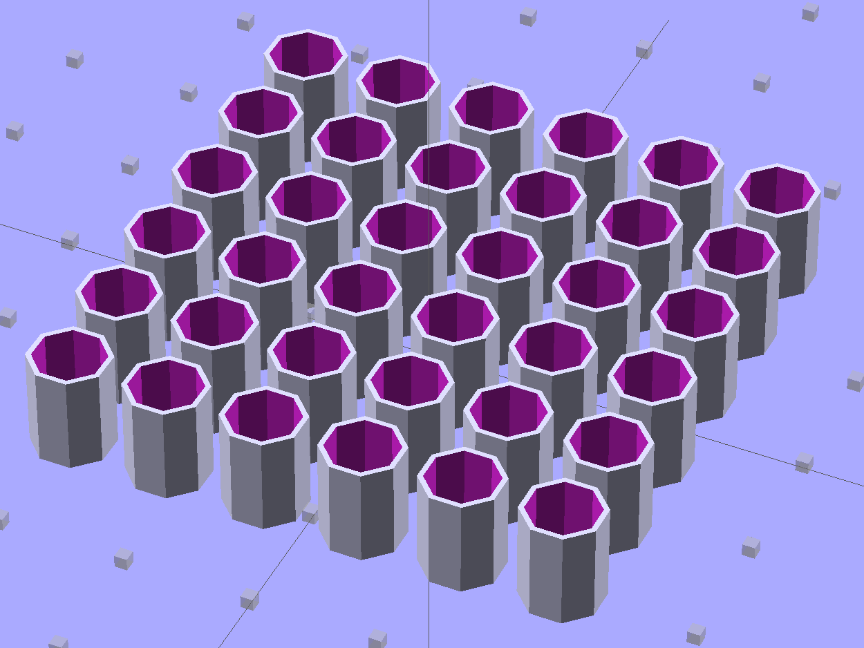
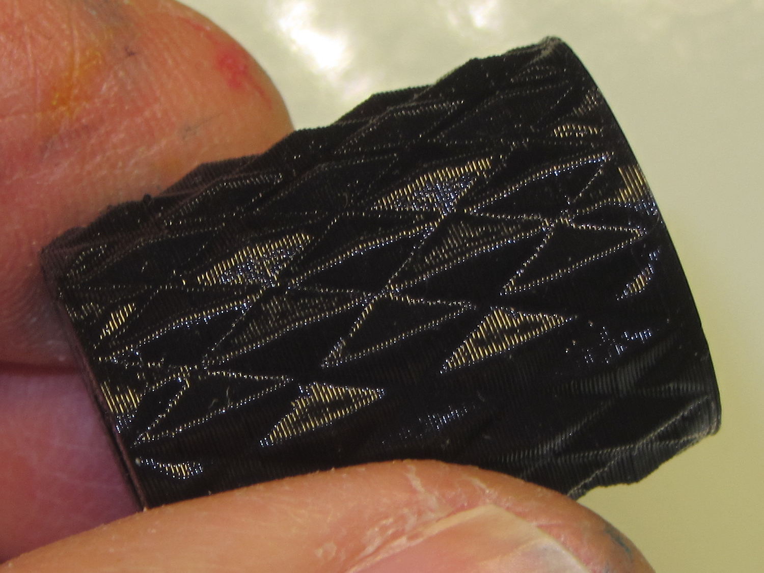
    These quilting pin caps are slightly longer than the previous version and, due to the M2’s smaller nozzle, have slightly thinner single-thread walls. Because Slic3r does a better (although not ideal) job of path planning than Skeinforge, it’s easier to create an array of the caps in the solid model than to manually add duplicates in Slic3r:

    Quilting Pin Cap - array
    Quilting Pin Cap – array

    They look like egg cases from Prometheus:

    Quilting pin cap array - on platform
    Quilting pin cap array – on platform

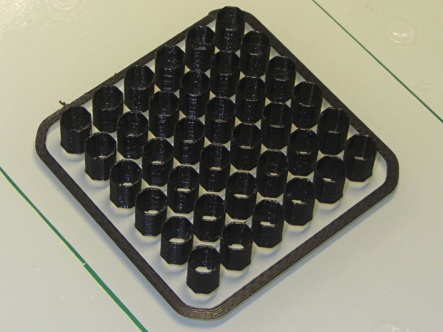
    Fill with silicone caulk on waxed paper and they look even more like that:

    Quilting pin caps - silicone fill
    Quilting pin caps – silicone fill

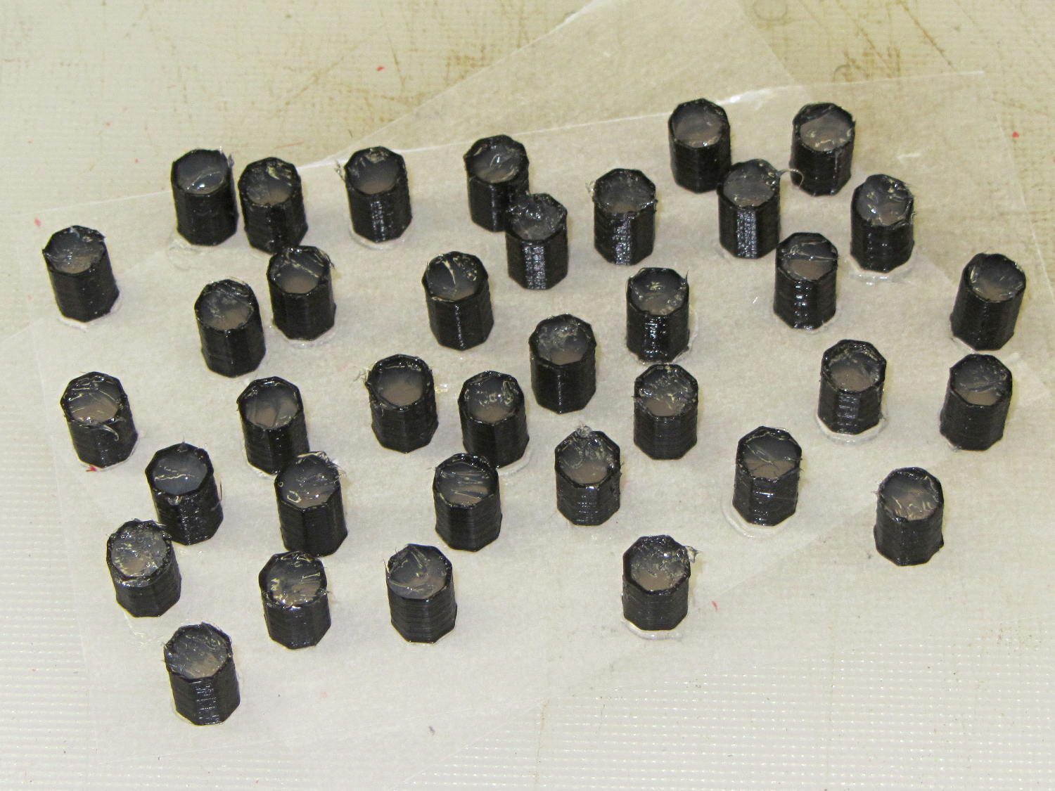
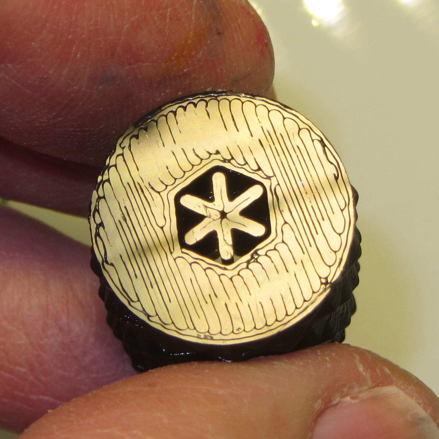
    Fast-forward a few days, rub off the excess caulk, trim off a few blobs, and they’re ready for presentation:

    Quilting pin caps - finished
    Quilting pin caps – finished

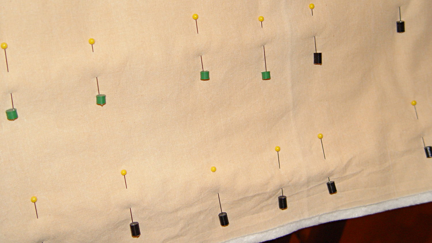
    In use, they look about like you’d expect:

    Quilting pin caps - in use
    Quilting pin caps – in use

    The pin caps I made from a 5 gallon bucket’s O-ring gasket didn’t work out well, as the plastic didn’t like being poked with pins and put up a stiff resistance. Silicone caulk has exactly the right consistency.

    When Mary ramps up a full-scale quilt, we’ll need a few hundred of the things. The commercial version has dropped to 40 cents each, which makes all this worthwhile.

    The OpenSCAD source code:

    // Quilting pin caps
    // Ed Nisley KE4ZNU April 2012
    //	January 2013 - modify for Slic3r and M2
    
    //- Extrusion parameters must match reality!
    //  Print with +1 shells and 3 solid layers
    
    ThreadThick = 0.20;
    ThreadWidth = 0.40;
    
    HoleWindage = 0.2;
    
    function IntegerMultiple(Size,Unit) = Unit * ceil(Size / Unit);
    
    Protrusion = 0.1;			// make holes end cleanly
    
    //----------------------
    // Dimensions
    
    ID = 5.0;
    OD = ID + 2*ThreadWidth;
    Length = 8.0;
    Sides = 8;
    
    CapArray = [6,6];			// XY layout of caps
    CapsOC = OD + 2.0;			// OC spacing
    
    //----------------------
    // Useful routines
    
    module PolyCyl(Dia,Height,ForceSides=0) {			// based on nophead's polyholes
    
      Sides = (ForceSides != 0) ? ForceSides : (ceil(Dia) + 2);
    
      FixDia = Dia / cos(180/Sides);
    
      cylinder(r=(FixDia + HoleWindage)/2,
               h=Height,
    	   $fn=Sides);
    }
    
    module ShowPegGrid(Space = 10.0,Size = 1.0) {
    
      RangeX = floor(100 / Space);
      RangeY = floor(125 / Space);
    
    	for (x=[-RangeX:RangeX])
    	  for (y=[-RangeY:RangeY])
    		translate([x*Space,y*Space,Size/2])
    		  %cube(Size,center=true);
    
    }
    
    module PinCap() {
    	rotate(180/Sides) {
    		difference() {
    		PolyCyl(OD,Length,8);
    		translate([0,0,-Protrusion])
    			PolyCyl(ID,(Length + 2*Protrusion),8);
    		}
    	}
    
    }
    
    //----------------------
    // Build them!
    
    ShowPegGrid();
    
    translate([(-CapsOC*(CapArray[0] - 1)/2),(-CapsOC*(CapArray[1] - 1)/2),0])
    	for (i=[0:(CapArray[0] - 1)],j=[0:(CapArray[1] - 1)])
    		translate([i*CapsOC,j*CapsOC,0])
    			PinCap();
    

    They seem to work pretty well…

  • Using a 3-way X10 Wall Switch As a 2-way Switch

    The pushbutton on the X10 wall switch controlling the fiercely incandescent lamp over the kitchen table has gotten erratic, so I dug into the Big Box o’ X10 Crap for a replacement. Turns out The Box has only 3-way switches, but the lamp needs a standard two-wire switch.

    The instruction sheet shows this diagram:

    X10 3-way Wall Switch Wiring
    X10 3-way Wall Switch Wiring

    The pushbutton on the CS277 “Companion” switch connects the red lead to the two blue leads. The blue leads are always connected together and carry the lamp current, so the red lead is just a signal from the remote button.

    The WS477 “Master” switch will work as an ordinary switch if you cap the red lead with a wire nut and tuck it into the box.

    Done!

  • Monthly Science: Air Temperatures

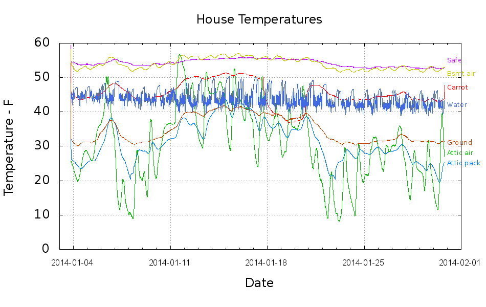
    This collects the temperature data points from the Hobo data loggers for the last month:

    Temperatures
    Temperatures

    Things to ponder:

    • The carrot buckets sat under the patio at the start of the month and moved indoors twice, marked by the humps. The early part of their curve doesn’t track the patio ground temperature nearly as well as it did during the three days at 18 Jan. We’re not sure why.
    • The water temperature sensor clamps to the copper pipe just inside the wall, so the low points measure outdoor water on its way past. The high points rise toward the basement air temperature (measured a few feet away), but the wall / earth around the pipe holds it below the air.
    • The basement safe looks like a good proxy for the average daily air temperature.
    • The attic insulation I added long ago seems to be working hard & doing swell.

    I cleaned up the data files manually, using those sed pipes, because of inadequate Bash-fu; I can’t figure out how to escape-quote the input file names and make temporary files work inside a Bash for;do;end construct that would rip through all the CSV files in one shot.

    On the other paw, the chart came out pretty well; I can now specify X-axis date ranges with some assurance of getting the right results.

    The Bash / Gnuplot script that made it happen:

    #!/bin/sh
    #-- overhead
    export GDFONTPATH="/usr/share/fonts/truetype/"
    ofile=Temperatures.png
    echo Output file: ${ofile}
    #-- do it
    gnuplot << EOF
    #set term x11
    set term png font "arialbd.ttf" 18 size 950,600
    set output "${ofile}"
    set title "House Temperatures"
    set key noautotitles left bottom
    unset mouse
    set bmargin 4
    set grid xtics ytics
    set timefmt "%m/%d/%Y %H:%M:%S"
    set xdata time
    set xlabel "Date"
    set format x "%Y-%m-%d"
    set xrange ["01/03/2014":]
    set xtics font "arial,12"
    #set mxtics 2
    #set logscale y
    #set ytics nomirror autofreq
    set ylabel "Temperature - F"
    #set format y "%4.0f"
    #set yrange [30:90]
    #set mytics 2
    #set y2label "right side variable"
    #set y2tics nomirror autofreq 2
    #set format y2 "%3.0f"
    #set y2range [0:200]
    #set y2tics 32
    #set rmargin 9
    set datafile separator ","
    set label 1 "Attic pack" at "01/31/2014",25 left font "arialbd,10" tc lt 3
    set label 2 "Attic air"  at "01/31/2014",28 left font "arialbd,10" tc lt 2
    set label 3 "Safe"       at "01/31/2014",55 left font "arialbd,10" tc lt 4
    set label 4 "Carrot"     at "01/31/2014",47 left font "arialbd,10" tc lt 1
    set label 5 "Ground"     at "01/31/2014",31 left font "arialbd,10" tc lt 6
    set label 6 "Bsmt air"   at "01/31/2014",51 left font "arialbd,10" tc lt 7
    set label 7 "Water"      at "01/31/2014",42 left font "arialbd,10" tc lt 8
    #set arrow from 2.100,110 to 2.105,103 lt 1 lw 2 lc 0
    plot	\
        "Attic.csv"  using 2:3 with lines lt 3 lw 1,\
        "Attic.csv"  using 2:4 with lines lt 2 lw 1,\
        "Safe.csv"   using 2:3 with lines lt 4 lw 1,\
        "Carrot.csv" using 2:3 with lines lt 1 lw 1,\
        "Patio.csv"  using 2:3 with lines lt 6 lw 1,\
        "Water.csv"  using 2:3 with lines lt 7 lw 1,\
        "Water.csv"  using 2:5 with lines lt 8 lw 1
    
    EOF
    
  • Modified Quilting Foot: Speed Wrench Knob

    The Nyloc nut atop that modified quilting foot requires more grip than fingers can provide:

    Modified Darning Foot - in action
    Modified Darning Foot – in action

    The “precision” wrench I adapted to that nut works for small adjustments, but for larger ones it’s easier to take the foot off and spin this knob:

    Quilting Foot Knob - knurling
    Quilting Foot Knob – knurling

    It has a hex opening in each end that fits the nut, with a through hole for the bolt. The top looks exactly like you’d expect:

    Quilting Foot Knob - top
    Quilting Foot Knob – top

    The bottom needs a bit of support:

    Quilting Foot Knob - bottom support
    Quilting Foot Knob – bottom support

    The solid model shows off the support in color:

    Quilting Foot Knob
    Quilting Foot Knob

    The OpenSCAD source code doesn’t have many surprises:

    // Quilting foot knob
    // Ed Nisley KE4ZNU January 2013
    
    use <knurledFinishLib_v2.scad>
    
    //- Extrusion parameters must match reality!
    //  Print with +1 shells and 3 solid layers
    
    ThreadThick = 0.20;
    ThreadWidth = 0.40;
    
    HoleWindage = 0.2;
    
    function IntegerMultiple(Size,Unit) = Unit * ceil(Size / Unit);
    
    Protrusion = 0.1;			// make holes end cleanly
    
    //----------------------
    // Dimensions
    
    KnobOD = 20.0;
    KnobLength = 25.0;
    KnobSides = 12;
    
    DiamondLength = KnobLength/3;
    DiamondWidth = DiamondLength/2;
    DiamondDepth = 1.0;
    
    NutOD = 7.0;				// across flats!
    NutLength = 6.0;
    ScrewOD = 4.0;
    
    DoSupport = true;
    
    //----------------------
    // Useful routines
    
    module PolyCyl(Dia,Height,ForceSides=0) {			// based on nophead's polyholes
    
      Sides = (ForceSides != 0) ? ForceSides : (ceil(Dia) + 2);
    
      FixDia = Dia / cos(180/Sides);
    
      cylinder(r=(FixDia + HoleWindage)/2,
               h=Height,
    	   $fn=Sides);
    }
    
    module ShowPegGrid(Space = 10.0,Size = 1.0) {
    
      RangeX = floor(100 / Space);
      RangeY = floor(125 / Space);
    
    	for (x=[-RangeX:RangeX])
    	  for (y=[-RangeY:RangeY])
    		translate([x*Space,y*Space,Size/2])
    		  %cube(Size,center=true);
    
    }
    
    module Knob() {
    	rotate(180/Sides) {
    		difference() {
    //			cylinder(r=KnobOD/2,h=KnobLength,$fn=KnobSides);
    			render(convexity=10)
    			knurl(k_cyl_hg=KnobLength,
    				  k_cyl_od=KnobOD,
    				  knurl_wd=DiamondWidth,
    				  knurl_hg=DiamondLength,
    				  knurl_dp=DiamondDepth,
    				  e_smooth=DiamondLength/2);
    			translate([0,0,-Protrusion])
    				PolyCyl(ScrewOD,(KnobLength + 2*Protrusion),6);
    			translate([0,0,(KnobLength - NutLength)])
    				PolyCyl(NutOD,(NutLength + Protrusion),6);
    			translate([0,0,-Protrusion])
    				PolyCyl(NutOD,(NutLength + Protrusion),6);
    		}
    	}
    }
    
    module Support() {
    	color("Yellow")
    		for (Seg=[0:5]) {
    			rotate(360*Seg/6)
    			translate([0,0,(NutLength - ThreadThick)/2])
    				cube([(NutOD - 1*ThreadWidth),
    						2*ThreadWidth,
    						(NutLength - ThreadThick)],
    						center=true);
    			}
    }
    
    //----------------------
    // Build them!
    
    ShowPegGrid();
    
    Knob();
    
    if (DoSupport)
    	Support();
    

    Mary likes it… and thinks I’m being silly. She’s right, of course.

  • Forcing Pulseaudio DisplayPort Volume Initialization

    It turns out that the audio-over-HDMI/DisplayPort channel which, for whatever reason, is the only way to get audio out of the Optiplex 980 with the big Dell U2711 monitor starts up AT MAXIMUM VOLUME! regardless of the GUI’s Pulseaudio mixer setting that’s diligently saved-and-restored across sessions. That makes a certain perverse sense, as the digital-to-analog converter & power amp live inside the monitor.

    Manually adjusting the GUI mixer by one click, either up or down, forces the new setting out over the digital link to the monitor, after which the audio output corresponds to the mixer; I never remember that until just after some dipshit auto-play video lights up with a fanfare.

    Setting the mixer to the same value doesn’t force an update, so the obvious solution (at least to me) of sending a fixed initial value doesn’t work; it’s optimized away. I think that’s why the initial update doesn’t happen: the stored volume is the same as the, ah, stored volume, so there’s no need to tell the monitor.

    The automatic solution involves putting two more commands in my ever-growing ~/.config/startup.sh:

    amixer -D pulse sset Master 26%
    amixer -D pulse sset Master 1%-
    

    That sets a rational level (which might be the same as the existing one from the previous session), then changing it by one tiny click to force the new value out to the monitor.

    And then It Just Works…