Ed Nisley's Blog: Shop notes, electronics, firmware, machinery, 3D printing, laser cuttery, and curiosities. Contents: 100% human thinking, 0% AI slop.
Recumbent Riders – North Grand Avenue Crossing – 2014-04-05
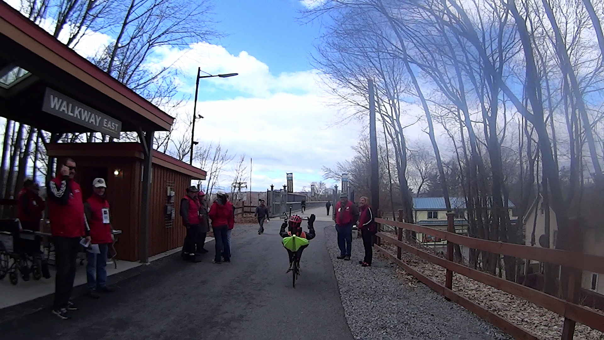
A highracer gingerly navigates the low-speed gauntlet to the Walkway Over the Hudson:
Recumbent Riders – Walkway Over the Hudson Entrance – 2014-04-05
The pix come from the Sony HDR-AS30V helmet camera video, set to 1920×1080 / 120° @ 60 frame/s. They’ve had a bit of refocusing and color adjustment, but nothing can dramatically improve them. The video looks better only because eyes aren’t as fussy with moving images. I’m not red-hot pleased with the resolution & compression, but the camera is what it is.
The lens carried a smear on the upper-right quadrant that shows the sensitivity of the optical path.
Memo to Self: Clean the lens and keep fingers off!
That’s harder than it may seem. The Start button is on the back of the body, recessed far enough into the skeleton frame to require an index finger rather than a thumb, and it’s remarkably easy to touch the bulging fisheye lens with your (well, my) thumb; a touch is all it takes to create a nice smear.
I started and ended at home, rather than at the Hopewell Junction end, but you get the general idea:
As I recall, a few weeks after I bought this packing tape dispenser, I dropped it with the nut downward, whereupon all six of the little tabs that were supposed to hold the tape roll in place broke off, allowing the roll to walk off the holder. Having put up with that for far too long (I don’t do a lot of shipping these days), I finally drilled and tapped three 4-40 holes and ran a trio of setscrews against the inside of the roll core:
Packing tape dispenser – improved spool holder
The holes are angled so that the setscrews bite into the core just enough to prevent it from walking away, but I can still pull the roll off when it’s empty.
A rough estimate of the volume and measurement thereof:
Assume 1 cm slab thickness for mold cavities 4 or 5 mm deep
Measure size of base plate in cm (given by OpenSCAD script in mm)
Compute slab volume in cubic cm = millliliters (ignoring mold cavity volumes)
Divide by 2 to find volume of each silicone component
Mark that volume on the side of two sacrificial containers
Pour silicone components into those containers
Pour one into the other, mix twice as long as you think you should
Scrupulously avoid cross-contaminating the original containers!
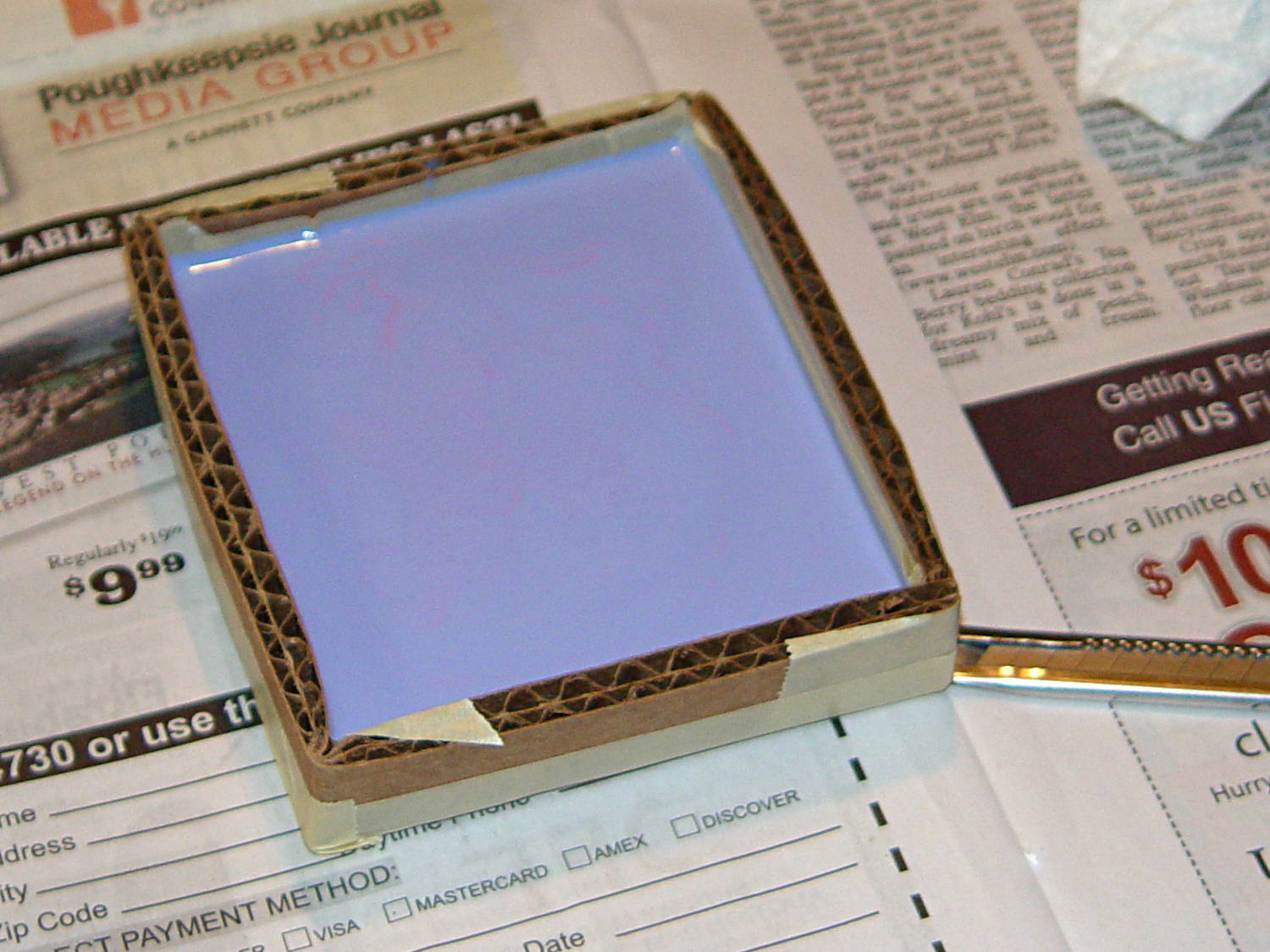
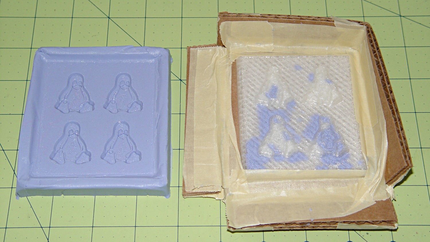
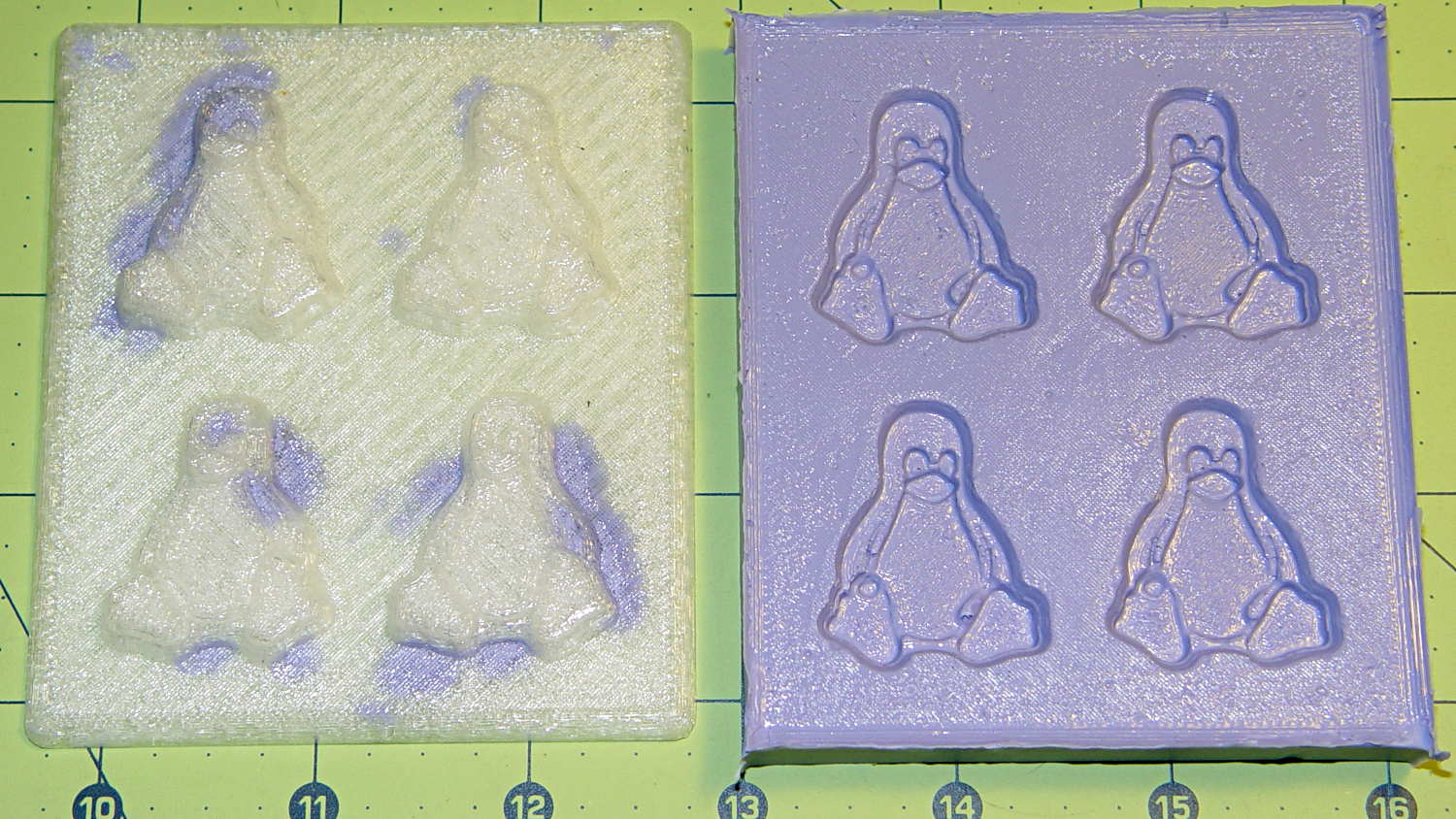
Fast-forward overnight, cut the tape, and peel the silicone negative off the positive:
Tux 2×2 mold – opened
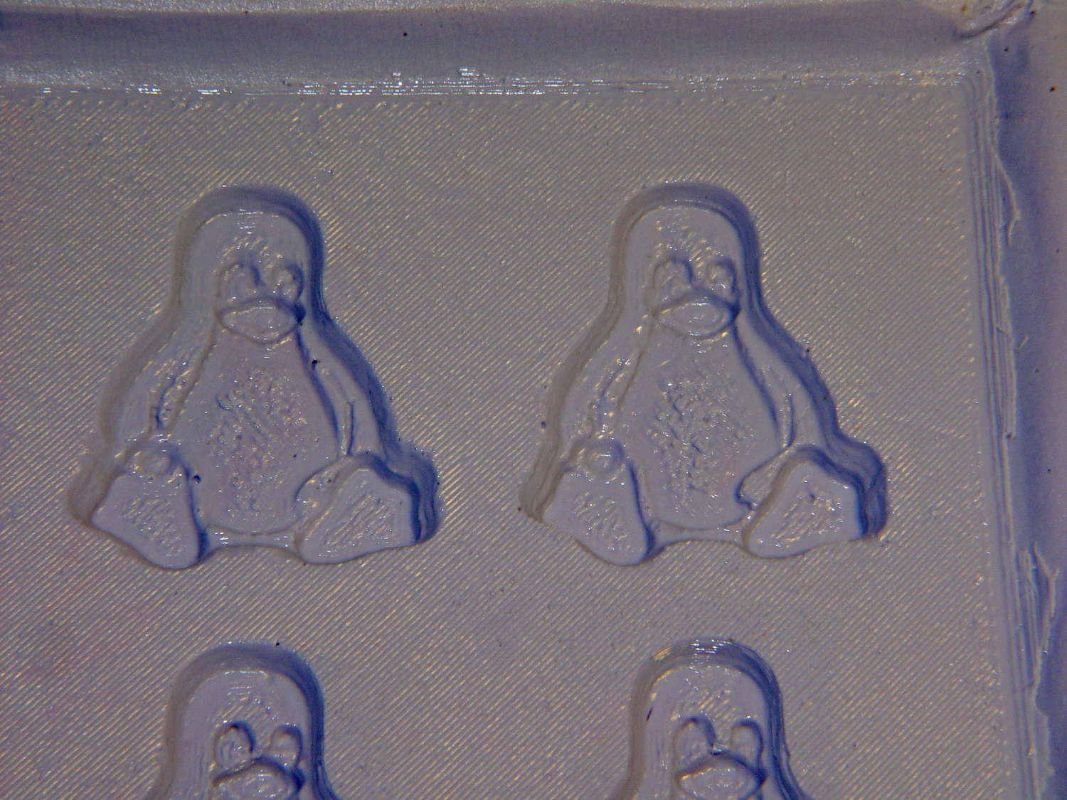
The top surface of the 3D printed positive wasn’t completely water silicone-tight, so the silicone leaked through the top and filled part of the interior. No harm done, but I wasn’t expecting that. The interior of the silicone negative came out pretty well, although you can see some small bubble cavities that may be due to air leaking out through the top of the positive:
Tux 2×2 mold – negative detail
The hand-knitted texture of the 3D printing process comes through very well, which is a Good Thing in this application. If you don’t like that, you can devote considerable time & attention to removing all traces of the production process.
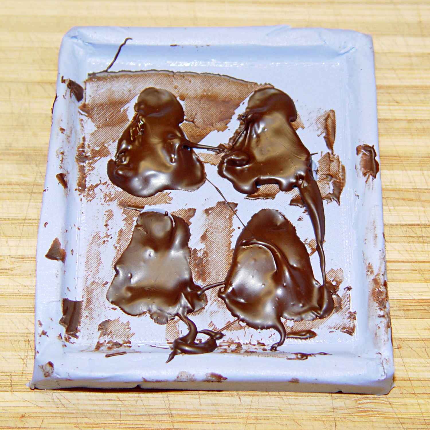
As a proof of concept, I melted and tempered four Dove Dark Chocolate Promises, then poured the chocolate into the cavities:
Tux 2×2 mold – filled
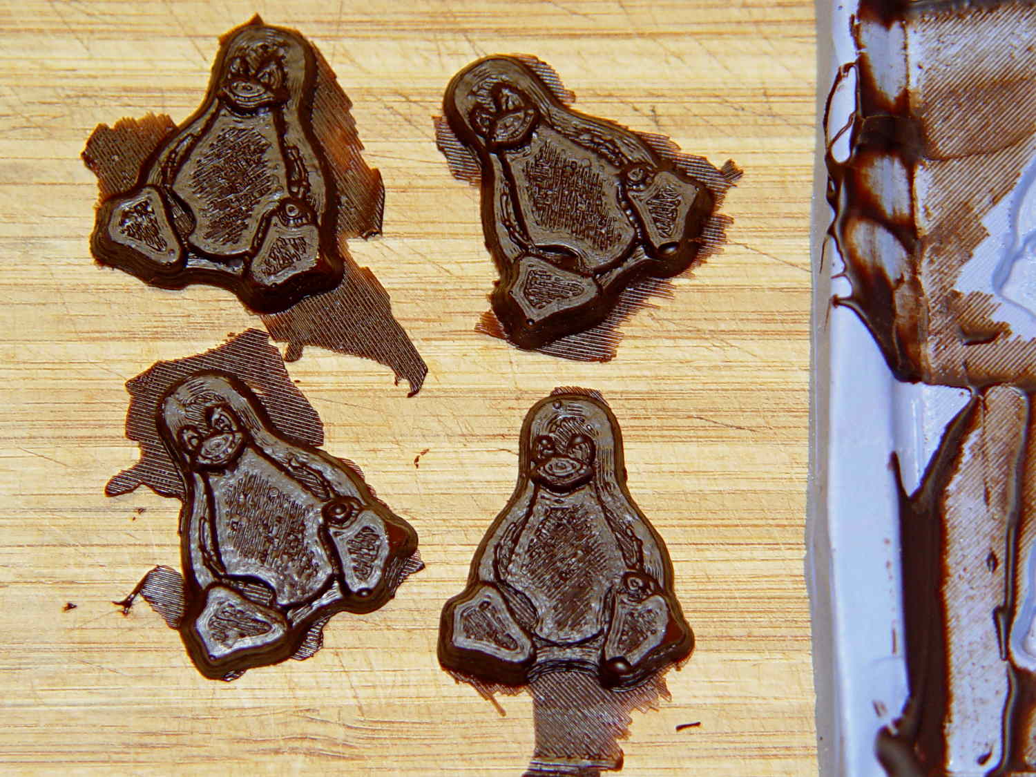
The tempering followed a fairly simple process that worked reasonably well, but the chocolate obviously wasn’t liquid when I poured it. The results looked pretty good, in a textured sort of way:
Tux chocolates – silicone mold
Flushed with success, I tweaked the mold to eliminate the raised lip around the edge, printed another positive plate, mixed up more silicone rubber, paid more attention to getting rid of the bubbles, and got this result:
Tux 2×2 mold 2 – opened
The printed surface still isn’t silicone-tight, which began to puzzle me, but the result looked pretty good.
After some fiddling around, though, I think printing the entire mold array isn’t the way to go. OpenSCAD can handle these 2×2 arrays, but a slightly tweaked Tux model (about which, more later) grossly increased the processing time and memory usage; OpenSCAD (and its CGAL geometry back end) filled all 4 GB of RAM, then blotted up 5 GB of swap space, ran for well over half an hour, and totally locked up the desktop UI for the duration.
It’s certainly infeasible to print the larger array on a sizable base plate that you’d need for a real project. I think printing multiple copies of a single model (duplicating them in the slicer, which is fast & easy), then attaching them to a plain base will work better. There’s no need to print the base plate, either, as a serrated top surface doesn’t buy anything; acrylic (or some such) sheet is cheap, flat, and readily available.
The Bash scripts and OpenSCAD programs below don’t produce exactly the same results you see above, mostly because I screwed around with them while discovering the reasons why doing it this way doesn’t make sense, but they can serve as a starting point if you must convince yourself, too.
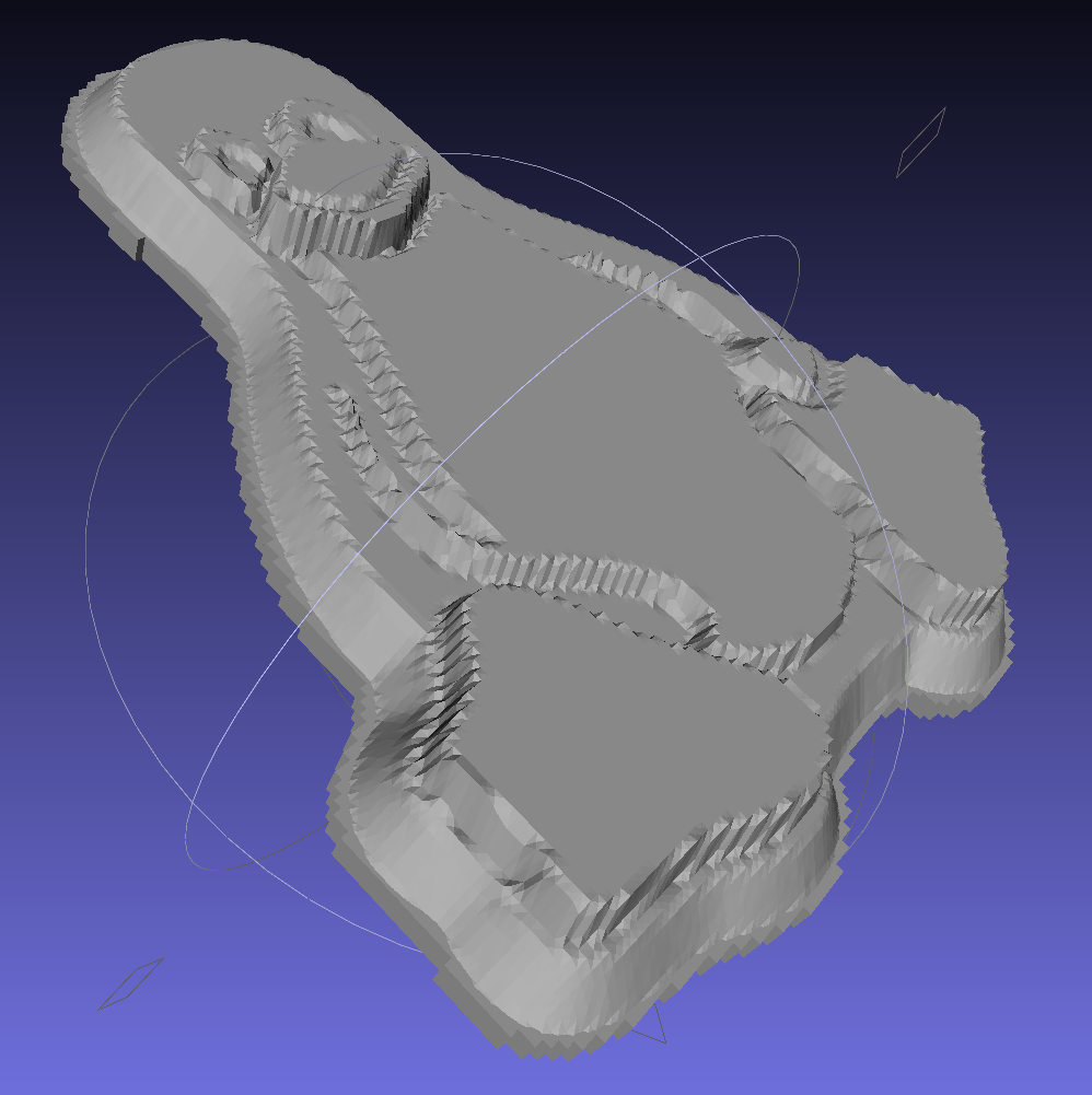
This Bash script produces a single positive mold item from a height map image:
// Mold positive pattern from grayscale height map
// Ed Nisley KE4ZNU - March 2014 - adapted from cookie press, added alignment pins

//-----------------
// Mold files

fnMap = "Tux_map.dat";					// override with -D 'fnMap="whatever.dat"'
fnPlate = "Tux_plate.dat";				// override with -D 'fnPlate="whatever.dat"'

DotsPerMM = 3.0;						// overrride with -D DotsPerMM=number

MapHeight = 4.0;						// overrride with -D MapHeight=number

ImageX = 100;							// overrride with -D ImageX=whatever
ImageY = 100;

UsePins = true;

MapScaleXYZ = [1/DotsPerMM,1/DotsPerMM,MapHeight/255];
PlateScaleXYZ = [1/DotsPerMM,1/DotsPerMM,1.0];

echo("Press File: ",fnMap);
echo("Plate File: ",fnPlate);

echo(str("ImageX:",ImageX," ImageY: ", ImageY));
echo(str("Map Height: ",MapHeight));
echo(str("Dots/mm: ",DotsPerMM));
echo(str("Scale Map: ",MapScaleXYZ,"  Plate: ",PlateScaleXYZ));

//- Extrusion parameters - must match reality!

ThreadThick = 0.25;
ThreadWidth = 2.0 * ThreadThick;

//- Buid parameters

PlateThick = IntegerMultiple(1.0,ThreadThick);		// solid plate under press relief

PinOD = 1.75;				// locating pin diameter
PinDepth = PlateThick;		//  ... depth into bottom surface = total length/2
PinOC = 20.0;				// spacing within mold item

echo(str("Pin depth: ",PinDepth," spacing: ",PinOC));

//- Useful info

function IntegerMultiple(Size,Unit) = Unit * ceil(Size / Unit);

HoleWindage = 0.2;

Protrusion = 0.1;						// make holes & unions work correctly

MaxConvexity = 5;						// used for F5 previews in OpenSCAD GUI

ZFuzz = 0.2;							// numeric chaff just above height map Z=0 plane

//-----------------
// Import plate height map, slice off a slab to define outline

module Slab(Thick=1.0) {
	intersection() {
		translate([0,0,Thick/2])
			cube([2*ImageX,2*ImageY,Thick],center=true);
		scale(PlateScaleXYZ)
			difference() {
				translate([0,0,-ZFuzz])
					surface(fnPlate,center=true,convexity=MaxConvexity);
				translate([0,0,-1])
					cube([2*ImageX,2*ImageY,2],center=true);
			}
	}
}

//- Put peg grid on build surface

module ShowPegGrid(Space = 10.0,Size = 1.0) {

	Range = floor(50 / Space);

	for (x=[-Range:Range])
	  for (y=[-Range:Range])
		translate([x*Space,y*Space,Size/2])
			%cube(Size,center=true);
}

//-- convert cylinder to low-count polygon

module PolyCyl(Dia,Height,ForceSides=0) {			// based on nophead's polyholes

  Sides = (ForceSides != 0) ? ForceSides : (ceil(Dia) + 2);

  FixDia = Dia / cos(180/Sides);

  cylinder(r=(FixDia + HoleWindage)/2,
           h=Height,
	   $fn=Sides);
}

//-- Locating pin hole with glue recess
//  Default length is two pin diameters on each side of the split

module LocatingPin(Dia=PinOD,Len=0.0) {

	PinLen = (Len != 0.0) ? Len : (4*Dia);

	translate([0,0,-ThreadThick])
		PolyCyl((Dia + 2*ThreadWidth),2*ThreadThick,4);

	translate([0,0,-2*ThreadThick])
		PolyCyl((Dia + 1*ThreadWidth),4*ThreadThick,4);

	translate([0,0,-(Len/2 + ThreadThick)])
		PolyCyl(Dia,(Len + 2*ThreadThick),4);

}

//- Build it

//ShowPegGrid();

echo("Building mold");
union() {
	difference() {
		Slab(PlateThick + Protrusion);
		if (UsePins)
			for (i=[-1,1])
				translate([0,i*PinOC/2,0])
					rotate(180/4) LocatingPin(Len=2*PinDepth);
	}
	translate([0,0,PlateThick])							// cookie press height map
		scale(MapScaleXYZ)
		difference() {
			translate([0,0,-ZFuzz])
				surface(fnMap,center=true,convexity=MaxConvexity);
			translate([0,0,-1])
				cube([2*ImageX,2*ImageY,2],center=true);
		}
}
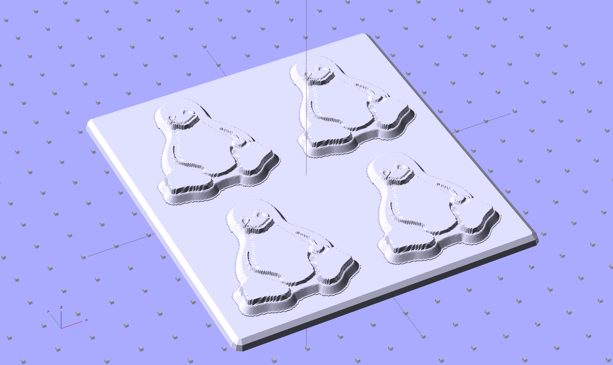
This OpenSCAD source code slides a base plate under an array of those mold items, with options for a separate plate using alignment pins or the combined plate-with-molds shown above:
// Positive mold framework for chocolate slabs
// Ed Nisley - KE4ZNU - March 2014

Layout = "FrameMolds";		// FramePins FrameMolds Pin

//- Extrusion parameters must match reality!
//  Print with 2 shells and 3 solid layers

ThreadThick = 0.20;
ThreadWidth = 0.40;

Protrusion = 0.1;			// make holes end cleanly

HoleWindage = 0.2;

//----------------------
// Dimensions

FileName = "Tux_Hi_Profile-positive.stl";	// overrride with -D

Molds = [2,2];					// count of molds within framework

MoldOC = [45.0,50.0];			// on-center spacing of molds
MoldSlab = 1.0;					// thickness of slab under molds

BaseThick = 3.0;

BaseSize = [(Molds[0]*MoldOC[0] + 0),(Molds[1]*MoldOC[1] + 0),BaseThick];
echo(str("Overall base: ",BaseSize));

PinOD = 1.75;					// locating pin diameter
PinLength = 2.0;				//  ... total length
PinOC = 20.0;				// spacing within mold item

//----------------------
// Useful routines

//- Put peg grid on build surface

module ShowPegGrid(Space = 10.0,Size = 1.0) {

	RangeX = floor(100 / Space);
	RangeY = floor(125 / Space);

	for (x=[-RangeX:RangeX])
		for (y=[-RangeY:RangeY])
			translate([x*Space,y*Space,Size/2])
			%cube(Size,center=true);

}

module PolyCyl(Dia,Height,ForceSides=0) {			// based on nophead's polyholes

  Sides = (ForceSides != 0) ? ForceSides : (ceil(Dia) + 2);

  FixDia = Dia / cos(180/Sides);

  cylinder(r=(FixDia + HoleWindage)/2,
           h=Height,
	   $fn=Sides);
}

// Locating pin hole with glue recess
//  Default length is two pin diameters on each side of the split

module LocatingPin(Dia=PinOD,Len=0.0) {

	PinLen = (Len != 0.0) ? Len : (4*Dia);

	translate([0,0,-ThreadThick])
		PolyCyl((Dia + 2*ThreadWidth),2*ThreadThick,4);

	translate([0,0,-2*ThreadThick])
		PolyCyl((Dia + 1*ThreadWidth),4*ThreadThick,4);

	translate([0,0,-(Len/2 + ThreadThick)])
		PolyCyl(Dia,(Len + 2*ThreadThick),4);

}

module LocatingPins(Length) {
	for (i=[-1,1])
	translate([0,i*PinOC/2,0])
		rotate(180/4)
		LocatingPin(Len=Length);
}

//-- import a single mold item

module MoldItem() {

//	intersection() {
		import(FileName,convexity=10);
//		cube([100,100,3],center=true);
//	}
}

//-- Overall frame shape

module Frame() {

//	translate([0,0,BaseSize[2]/2])		// platform under molds
//		cube(BaseSize,center=true);

	difference() {
		hull()
			for (i=[-1,1], j=[-1,1])
				translate([i*BaseSize[0]/2,j*BaseSize[1]/2,0])
					sphere(r=BaseThick);
		translate([0,0,-BaseThick])
			cube(2*BaseSize,center=true);
	}

}

//- Build it

ShowPegGrid();

if (Layout == "Pin")
	LocatingPin(Len=PinLength);

if (Layout == "Frame")
	Frame();

if (Layout == "FramePins")
	difference() {
		Frame();

		translate([-MoldOC[0]*(Molds[0] - 1)/2,-MoldOC[1]*(Molds[1] - 1)/2,0])
			for (i=[0:Molds[0]-1],j=[0:Molds[1]-1])
				translate([i*MoldOC[0],j*MoldOC[1],BaseSize[2]])
					LocatingPins(BaseThick);
	}

if (Layout == "FrameMolds") {
	Frame();
	translate([-MoldOC[0]*(Molds[0] - 1)/2,-MoldOC[1]*(Molds[1] - 1)/2,0])
		for (i=[0:Molds[0]-1],j=[0:Molds[1]-1])
			translate([i*MoldOC[0],j*MoldOC[1],BaseThick - MoldSlab + Protrusion])
			MoldItem();
}
The view through the front window (1950-vintage glass + storm window) at 1/500 s, f/4, ISO 100, auto-exposed to EV 0:
Front yard – normal exposure
The same view, using stacked 2 + 4 + 8 ND filters, at 1/3 s, f/4, ISO 100, auto-exposed to EV 0:
Front yard – ND2-4-8 filters
That blur to the left of the mailbox is a passing car, which is the whole point of heavy ND filtering: you can use absurdly long shutter times and still get a decent exposure.
I cannot explain the fact that the ND filters allegedly reduce the light by 14 stops, but the actual (auto) exposure increases by about 7 stops. They’re cheap non-coated K&F Concept Digital filters, of course, but …
There’s an obvious color shift toward red / magenta.
This is a placeholder so I can pick up the thought later on…
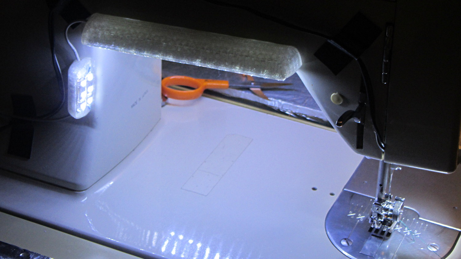
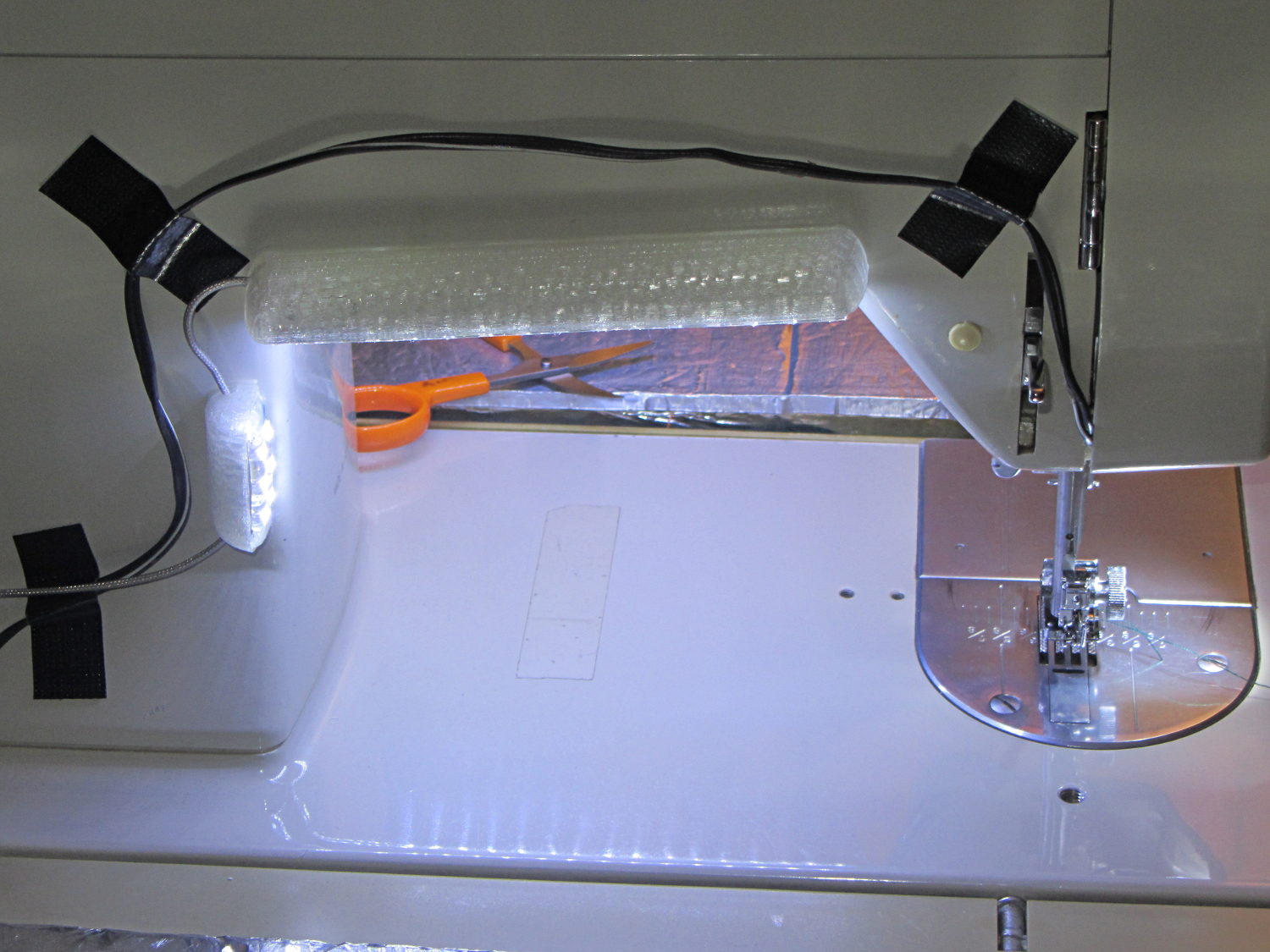
Natural PLA provides a nice, crystalline appearance:
Kenmore 158 Sewing Machine – Cool white LEDs – rear no flash
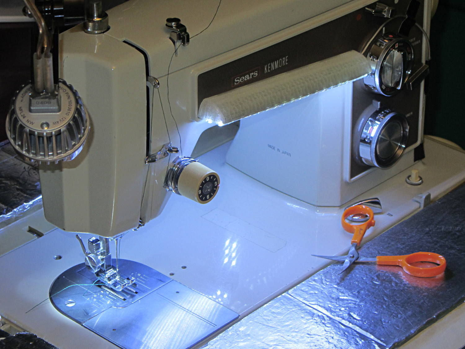
Cool white LEDs have somewhat higher lumen/watt efficiency, but the real gain came from doubling the number of LEDs:
Kenmore 158 Sewing Machine – Cool white LEDs – front flash
I overvolted the warm white LEDs to 14 V to get closer to 20 mA/segment, but the cool white ones run pretty close to 20 mA at 12 V, so I didn’t bother.
Commercial versions of this hack secure the wiring with little white clips and foam tape, so I should conjure up something like that. Mary specifically did not want the lights affixed under the arm, though, so those things weren’t even in the running.
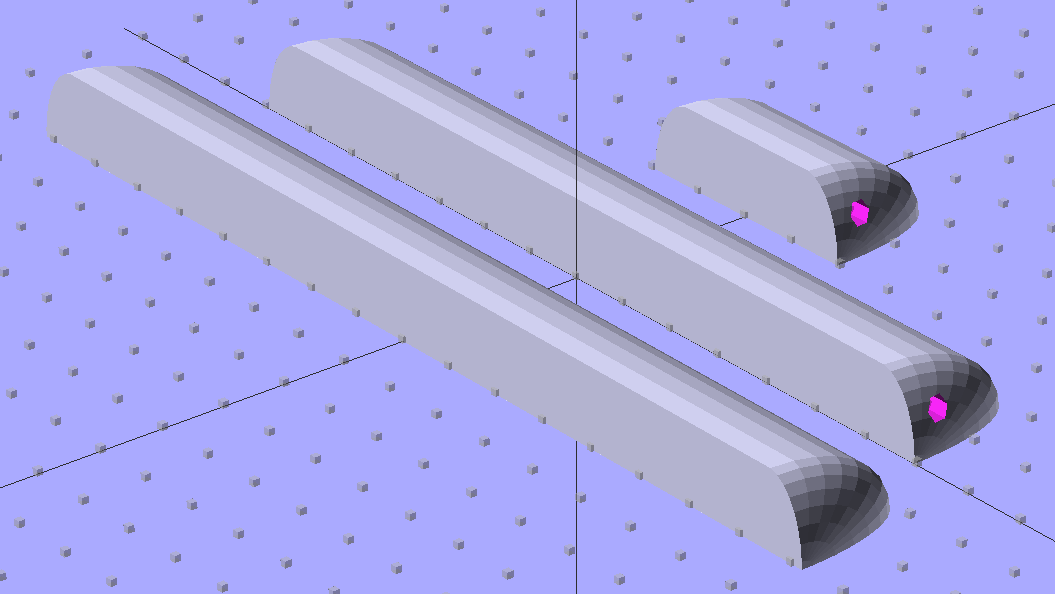
The OpenSCAD source code widens the mount and moves the wiring conduit a little bit, to simplify the connections to both strips, but is otherwise identical to the earlier version:
// LED Strip Lighting Brackets for Kenmore Model 158 Sewing Machine
// Ed Nisley - KE4ZNU - March 2014

Layout = "Build";			// Build Show Channels Strip

//- Extrusion parameters must match reality!
//  Print with 2 shells and 3 solid layers

ThreadThick = 0.20;
ThreadWidth = 0.40;

HoleWindage = 0.2;			// extra clearance

Protrusion = 0.1;			// make holes end cleanly

AlignPinOD = 1.70;			// assembly alignment pins: filament dia

inch = 25.4;

function IntegerMultiple(Size,Unit) = Unit * ceil(Size / Unit);

//----------------------
// Dimensions

Segment = [25.0,10.0,3.0];		//  size of each LED segment
SEGLENGTH = 0;
SEGWIDTH = 1;
SEGHEIGHT = 2;

WireChannel = 3.0;				// wire routing channel

StripHeight = 12.0;				// sticky tape width
StripSides = 8*4;

DefaultLayout = [1,2,"Wire","NoWire"];
NUMSEGS = 0;
NUMSTRIPS = 1;
WIRELEFT = 2;
WIRERIGHT = 3;

EndCapSides = StripSides;

CapSpace = 2.0;						// build spacing for endcaps
BuildSpace = 3.0;					// spacing between objects on platform

//----------------------
// Useful routines

module PolyCyl(Dia,Height,ForceSides=0) {			// based on nophead's polyholes

  Sides = (ForceSides != 0) ? ForceSides : (ceil(Dia) + 2);

  FixDia = Dia / cos(180/Sides);

  cylinder(r=(FixDia + HoleWindage)/2,
           h=Height,
           $fn=Sides);
}

module ShowPegGrid(Space = 10.0,Size = 1.0) {

  RangeX = floor(100 / Space);
  RangeY = floor(125 / Space);

	for (x=[-RangeX:RangeX])
	  for (y=[-RangeY:RangeY])
		translate([x*Space,y*Space,Size/2])
		  %cube(Size,center=true);

}

//-- The negative space used to thread wires into the endcap

module MakeWireChannel(Layout = DefaultLayout,Which = "Left") {

	EndCap = [(2*WireChannel + 1.0),Layout[NUMSTRIPS]*Segment[SEGWIDTH],StripHeight];	// radii of end cap spheroid

	HalfSpace = EndCap[0] * ((Which == "Left") ? 1 : -1);

	render(convexity=2)
	translate([0,Segment[SEGWIDTH]/2,0])
		intersection() {
			union() {
				cube([2*WireChannel,WireChannel,EndCap[2]],center=true);
				translate([-2*EndCap[0],0,EndCap[2]/2])
					rotate([0,90,0]) rotate(180/6)
						PolyCyl(WireChannel,4*EndCap[0],6);
			}
			translate([HalfSpace,0,(EndCap[2] - Protrusion)]) {
				cube(2*EndCap,center=true);
			}
		}
}

//-- The whole strip, minus wiring channels

module MakeStrip(Layout = DefaultLayout) {

	EndCap = [(2*WireChannel + 1.0),Layout[NUMSTRIPS]*Segment[SEGWIDTH],StripHeight];	// radii of end cap spheroid

	BarLength = Layout[NUMSEGS] * Segment[SEGLENGTH];				// central bar length

	hull()
		difference() {
			for (x = [-1,1])						// endcaps as spheroids
				translate([x*BarLength/2,0,0])
					resize(2*EndCap) rotate([0,90,0]) sphere(1.0,$fn=EndCapSides);
			translate([0,0,-EndCap[2]])
				cube([2*BarLength,3*EndCap[1],2*EndCap[2]],center=true);
			translate([0,-EndCap[1],0])
				cube([2*BarLength,2*EndCap[1],3*EndCap[2]],center=true);
		}

}

//-- Cut wiring channels out of strip

module MakeMount(Layout = DefaultLayout) {

	BarLength = Layout[NUMSEGS] * Segment[SEGLENGTH];

	difference() {
		MakeStrip(Layout);
		if (Layout[WIRELEFT] == "Wire")
			translate([BarLength/2,0,0])
				MakeWireChannel(Layout,"Left");
		if (Layout[WIRERIGHT] == "Wire")
			translate([-BarLength/2,0,0])
				MakeWireChannel(Layout,"Right");
	}
}

//- Build it

ShowPegGrid();

if (Layout == "Channels") {
	translate([ (2*WireChannel + 1.0),0,0]) MakeWireChannel(DefaultLayout,"Left");
	translate([-(2*WireChannel + 1.0),0,0]) MakeWireChannel(DefaultLayout,"Right");
}

if (Layout == "Strip") {
	MakeStrip(DefaultLayout);
}

if (Layout == "Show") {
	MakeMount(DefaultLayout);
}

if (Layout == "Build") {

	translate([0,(3*Segment[SEGWIDTH]),0]) MakeMount([1,2,"Wire","Wire"]);		// rear left side, vertical
	translate([0,0,0]) MakeMount([5,2,"Wire","NoWire"]);				// rear top, across arm
	translate([0,-(3*Segment[SEGWIDTH]),0]) MakeMount([6,2,"NoWire","Wire"]);	// front top, across arm
}
During my monthly data logging, I replace any weak CR2032 cells in the Hobo data loggers and, being that type of guy, I write the current date and the elapsed time since the last replacement on the top of the cells. This month I had to replace two cells:
Energizer CR2023 – early failures
Huh.
It seems the previous Energizer CR2023 cells in those loggers lasted for more than the usual year, but these cells from the same lot with the same date code failed in two weeks (my last monthly science was unusually late, because distraction). The YA date code (printed on the other side of the cell) isn’t helpful (that Q&A list shows the problem), but they’re supposed to have an eight year shelf life. As nearly as I can tell, these are getting on toward five years on my shelf, so maybe they spent a bit more time on somebody else’s shelf than the seller claimed.
A solderless breadboard sufficed for the simple circuitry behind the strobe controller:
Strobe Photography – control breadboard
I used a separate 7.5 V supply for the Arduino Pro Mini to keep the relay noise out of the VCC circuit, but that’s probably not really necessary; you could back-drive the Pro Mini’s regulator with +5 V and it’d be perfectly happy. There’s a +5 V wall wart for the relay, LEDs, and so forth.
Protip: you do not want to drive all the other circuitry through the Pro Mini’s tiny little regulator. Work out the power dissipation in the regulator caused by a 130 Ω relay, about 10 mA for the laser, 100 mA for the white LED, and whatever the Pro Mini draws. Yeah, some of those are intermittent loads, but work it out anyway.
A 1.5 V bench supply powers the Xenon strobe in place of the AA alkaline cell I used at first. The boost circuit pins the supply at 3 A for a few seconds, then settles at about 350 mA (!) while idling; no wonder the poor little AA cells don’t last very long!
The control program is also dead simple; it’s mostly a state machine that notices when the photocurrent drops to zero, then steps through a series of fixed delays while turning the laser, LED, and strobe outputs on and off.
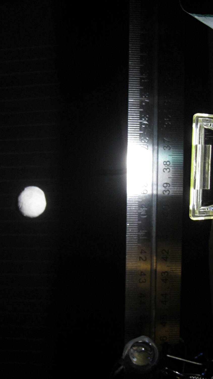
The default values highlight a falling object about 200 mm below the laser beam-break sensor, assuming you release the object just above the beam:
Ball at 200 mm – detail
The laser beam is at the 200 mm mark, so that ball passing 400 mm has dropped 200 mm.
The quadrature encoder knob recycles the same interrupt handler I used earlier, with the shaft button selecting either the LED delay (pushed) or the Xenon strobe delay (released). There’s precious little error checking, as befits a quick hack job, so use at your own risk…
The Arduino source code:
// Optical flash triggering
// Ed Nisley - KE4ANU - March 2014

//----------
// Pin assignments

const byte PIN_KNOB_A = 2;			// knob A switch - must be on ext interrupt 2
const byte PIN_KNOB_B = 4;			//  .. B switch
const byte PIN_KNOB_SWITCH = A3;	//  .. shaft push switch

const byte PIN_PHOTOCURRENT = A0;	// photodiode current input

const byte PIN_LASER = 8;   		// laser drive -active
const byte PIN_LED = 7;		   		// LED drive -active
const byte PIN_FLASH = 12;			// Xenon flash relay -active

const byte PIN_SYNC = 13;			// scope sync - and Arduino LED

//----------
// Constants

enum FALLING_STATES {F_IDLE,F_WAIT,F_DETECT,F_PREFALL,F_LED,F_MD,F_FLASH,F_CLEAR};

enum KNOB_STATES {KNOB_CLICK_0,KNOB_CLICK_1};

//----------
// Globals

const unsigned long UPDATEMS = 250;	// update displays only this many ms apart

volatile char KnobCounter = 0;
volatile byte KnobState;

byte Button, PrevButton;

byte Falling = F_IDLE;				// cold start the detection state machine

unsigned long FallStart;			// when we we detected the falling object

unsigned int DetectLevel = 200;		// ADC reading for object detection

unsigned int DelayLED = 1;			// ms from trigger detect to LED preflash

unsigned int DelayFlash = 180;		//  ... to Xenon flash

unsigned int DelayClear = 6000;		//  ... after impact to allow camera restart

const byte PulseLED = 50;			// ms LED on to pass motion detection threshold
const byte PulseFlash = 20;			// ms Xenon flash relay on

const unsigned int RelayAdvance = 3;	// ms relay activation to Xenon flash

unsigned long MillisNow;
unsigned long MillisThen;

//-- Helper routine for printf()

int s_putc(char c, FILE *t) {
  Serial.write(c);
}

//-- Knob interrupt handler

void KnobHandler(void)
{
	byte Inputs;
	Inputs = digitalRead(PIN_KNOB_B) << 1 | digitalRead(PIN_KNOB_A);  // align raw inputs
//	Inputs ^= 0x02;                             // fix direction

	switch (KnobState << 2 | Inputs) {
	case 0x00 : 				// 0 00 - glitch
        break;
	case 0x01 : 				 // 0 01 - UP to 1
        KnobCounter++;
		KnobState = KNOB_CLICK_1;
		break;
	case 0x03 : 				 // 0 11 - DOWN to 1
        KnobCounter--;
		KnobState = KNOB_CLICK_1;
		break;
	case 0x02 : 				 // 0 10 - glitch
        break;
	case 0x04 : 				 // 1 00 - DOWN to 0
        KnobCounter--;
		KnobState = KNOB_CLICK_0;
		break;
	case 0x05 : 				 // 1 01 - glitch
        break;
	case 0x07 : 				 // 1 11 - glitch
        break;
	case 0x06 : 				 // 1 10 - UP to 0
        KnobCounter++;
		KnobState = KNOB_CLICK_0;
		break;
	default :  					// something is broken!
        KnobCounter = 0;
		KnobState = KNOB_CLICK_0;
	}
}

//------------------
// Set things up

void setup() {

	pinMode(PIN_SYNC,OUTPUT);
	digitalWrite(PIN_SYNC,LOW);			// show we arrived

	pinMode(PIN_KNOB_B,INPUT_PULLUP);
	pinMode(PIN_KNOB_A,INPUT_PULLUP);
	pinMode(PIN_KNOB_SWITCH,INPUT_PULLUP);

    pinMode(PIN_LASER,OUTPUT);
    digitalWrite(PIN_LASER,HIGH);

    pinMode(PIN_LED,OUTPUT);
    digitalWrite(PIN_LED,HIGH);

    pinMode(PIN_FLASH,OUTPUT);
    digitalWrite(PIN_FLASH,HIGH);

	KnobState = digitalRead(PIN_KNOB_A);
	Button = PrevButton = !digitalRead(PIN_KNOB_SWITCH);

	attachInterrupt((PIN_KNOB_A - 2),KnobHandler,CHANGE);

	Falling = F_IDLE;

	Serial.begin(9600);
	fdevopen(&s_putc,0);				// set up serial output for printf()

	printf("Xenon Flash Trigger\r\nEd Nisley - KE4ZNU - March 2014\r\n");

	MillisThen = millis();

}

//------------------
// Go flash!

void loop() {

	MillisNow = millis();

	if (KnobCounter) {
		Button = !digitalRead(PIN_KNOB_SWITCH);
		if (Button)
			DelayLED += KnobCounter;
		else
			DelayFlash += KnobCounter;

		DelayLED = min(DelayLED,DelayFlash - PulseLED);
		printf("Knob: %d, LED: %d, Flash: %d\n",KnobCounter,DelayLED,DelayFlash);
		KnobCounter = 0;
	}

	digitalWrite(PIN_SYNC,HIGH);

	switch (Falling) {
	case F_IDLE :								// turn on laser for object detection
		digitalWrite(PIN_LASER,LOW);
		printf("Laser on, stabilizing... ");
		while (analogRead(PIN_PHOTOCURRENT) <= DetectLevel) {
			printf("*");
		}
		printf("\nReady!\n");
		Falling = F_WAIT;
		break;
	case F_WAIT :								// record starting time of beam break
		if (analogRead(PIN_PHOTOCURRENT) < DetectLevel) {
			FallStart = millis();
			Falling = F_DETECT;
		}
		break;
	case F_DETECT :								// turn off laser to signal detection
		digitalWrite(PIN_LASER,HIGH);
		Falling = F_PREFALL;
		break;
	case F_PREFALL :							// turn on LED to trigger camera motion detection
		if ((millis() - FallStart) >= DelayLED) {
			digitalWrite(PIN_LED,LOW);
			Falling = F_LED;
		}
		break;
	case F_LED : 								// turn off LED
		if ((millis() - FallStart) >= (DelayLED + PulseLED)) {
			digitalWrite(PIN_LED,HIGH);
			Falling = F_MD;
		}
		break;
	case F_MD :									// fire the strobe to take picture
		if ((millis() - FallStart) >= (DelayFlash - RelayAdvance)) {
			digitalWrite(PIN_FLASH,LOW);
			Falling = F_FLASH;
		}
		break;
	case F_FLASH :								// turn off strobe relay
		if ((millis() - FallStart) >= (DelayFlash - RelayAdvance + PulseFlash)) {
			digitalWrite(PIN_FLASH,HIGH);
    		printf("Flash with LED delay: %d, Xenon delay: %d ...",DelayLED,DelayFlash);
			Falling = F_CLEAR;
		}
		break;
	case F_CLEAR :								// wait for camera to recycle
		if ((millis() - FallStart) >= DelayClear) {
			printf("done\n");
			Falling = F_IDLE;
		}
		break;
	default :
		printf("** Bad Falling state: %02X",Falling);
		Falling = F_IDLE;
	}

	digitalWrite(PIN_SYNC,LOW);

	if ((MillisNow - MillisThen) > UPDATEMS) {
//		printf("State: %02X\n",Falling);
		MillisThen = MillisNow;
	}

}