Ed Nisley's Blog: Shop notes, electronics, firmware, machinery, 3D printing, laser cuttery, and curiosities. Contents: 100% human thinking, 0% AI slop.
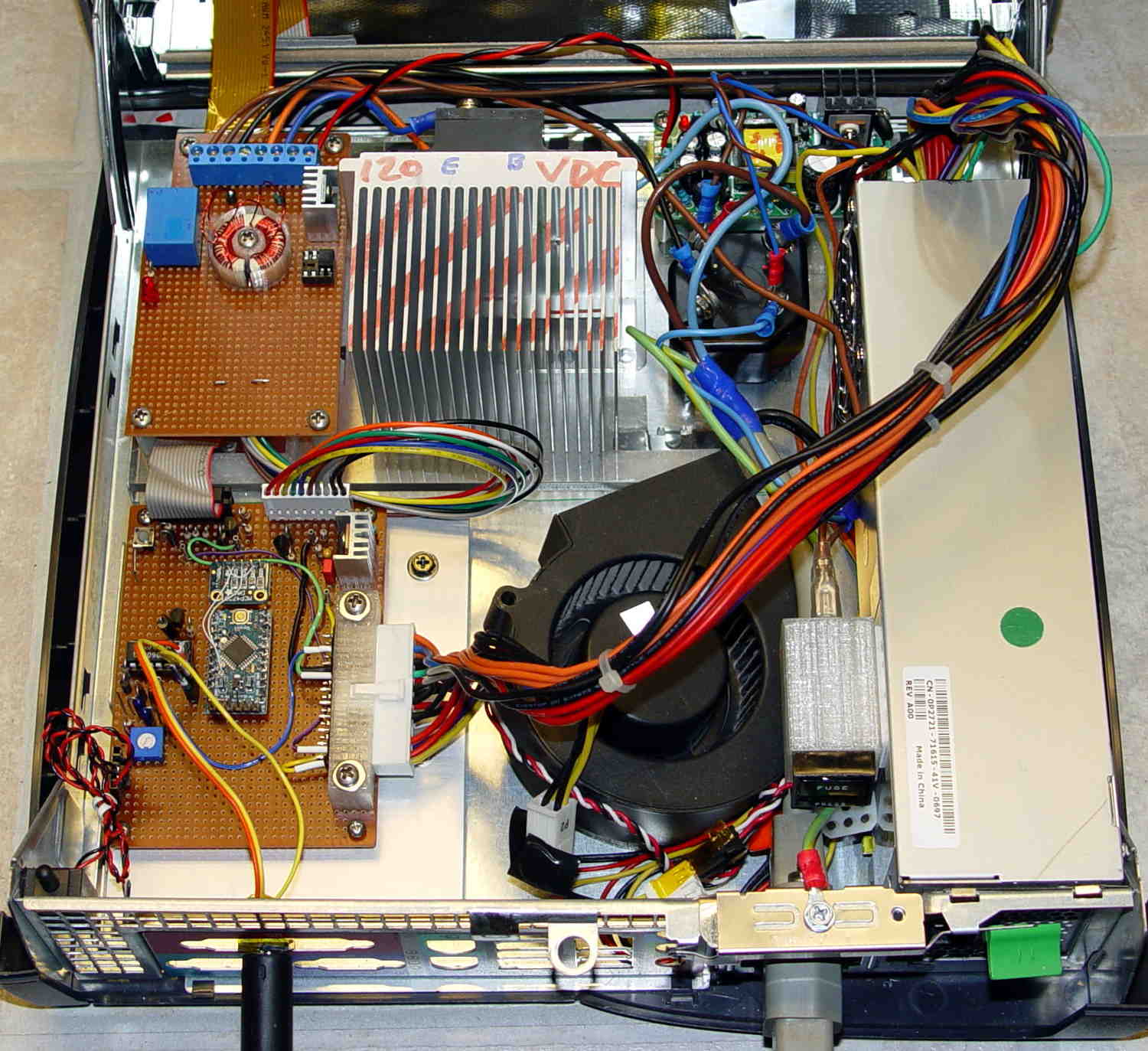
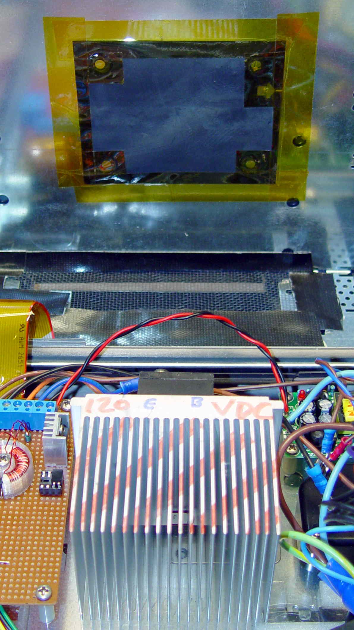
That polycarbonate slab holds most of the pieces in place, with the rest on the prototype board to the left of the monster heatsink:
Model 158 Controller – Interior Overview
That bulky wire harness got bent out of the way for the photo; normally, it’s jammed down beside the ATX power supply and over the blower.
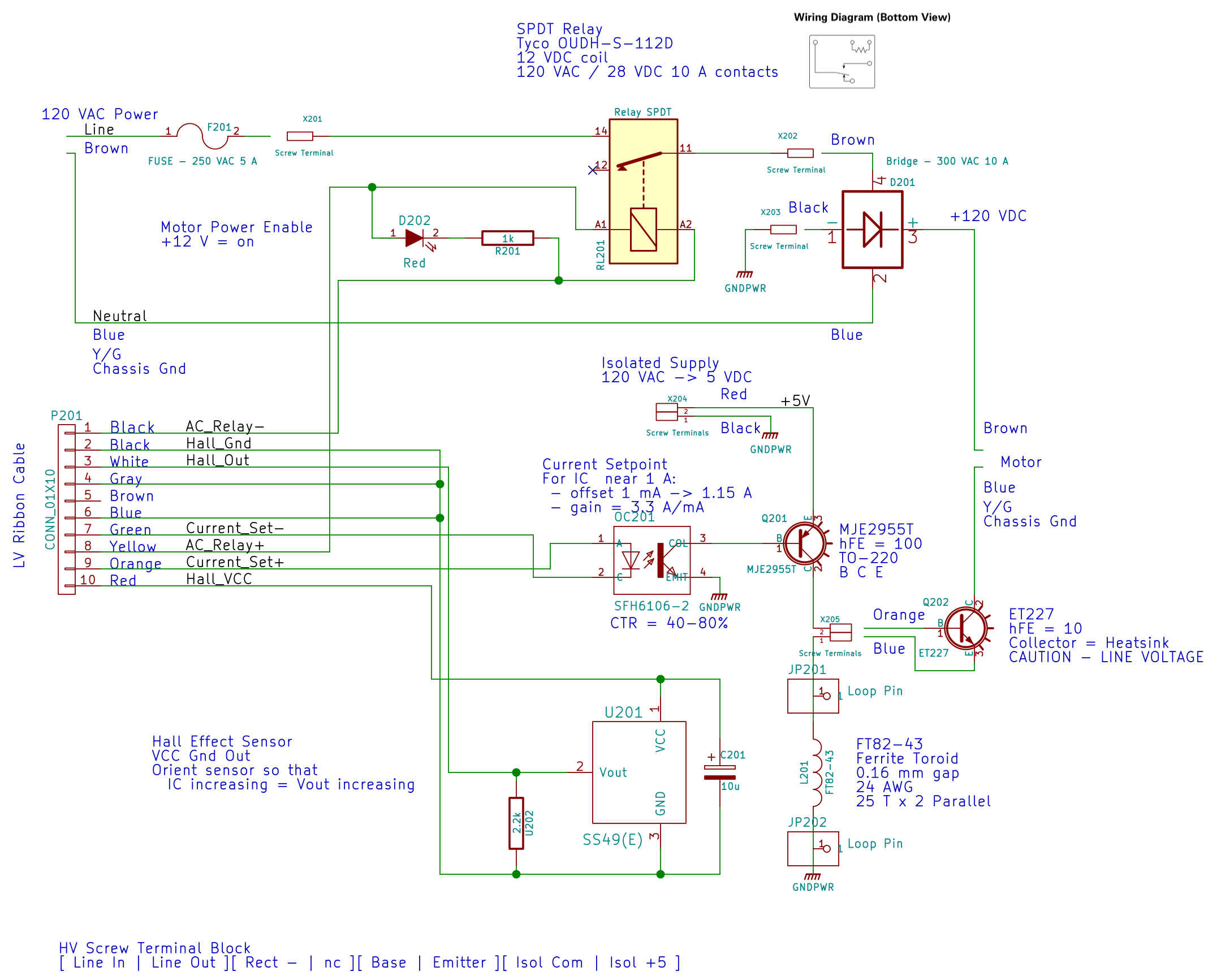
The AC Interface circuitry looks like this:
AC Power Interface
The relay on the top disconnects the AC line from the circuitry when the clamshell case opens.
The key hardware spreads neatly across the middle: the optoisolator, a 2955 PNP power transistor in a TO-220 case on a heatsink as a current amplifier, and the ET227 controlling the motor current. The gain of that mess depends strongly on the transistor temperatures, so there’s not much point in calibrating it. More on that later.
Down at the bottom of the schematic is the slit toroid and knockoff SS49(E) Hall effect sensor that senses the actual motor current.
A closer look at that board:
HV Interface board – detail
The board in the bottom left corner of the overview picture holds the Arduino Pro Mini that runs the whole show (so far, anyway), along with various & sundry analog circuitry that I’ll write up in a bit.
Conspicuous by their absence:
Motor speed sensing
Shaft position sensing
Power to the LED strip lights
Permanent mount for the pedal cable socket
Now I can make measurements without killing myself…
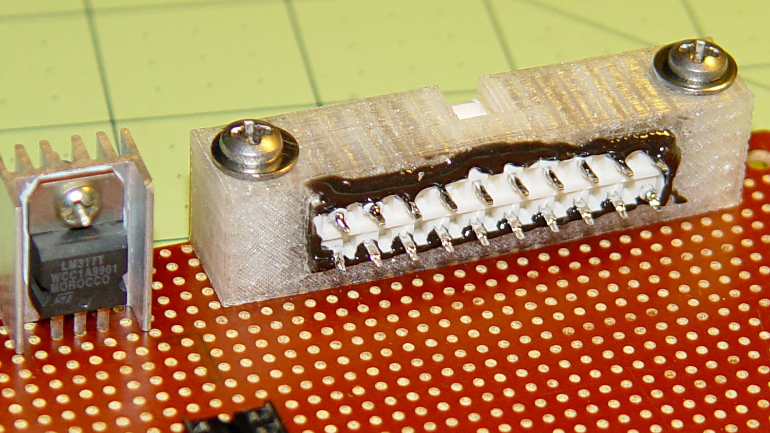
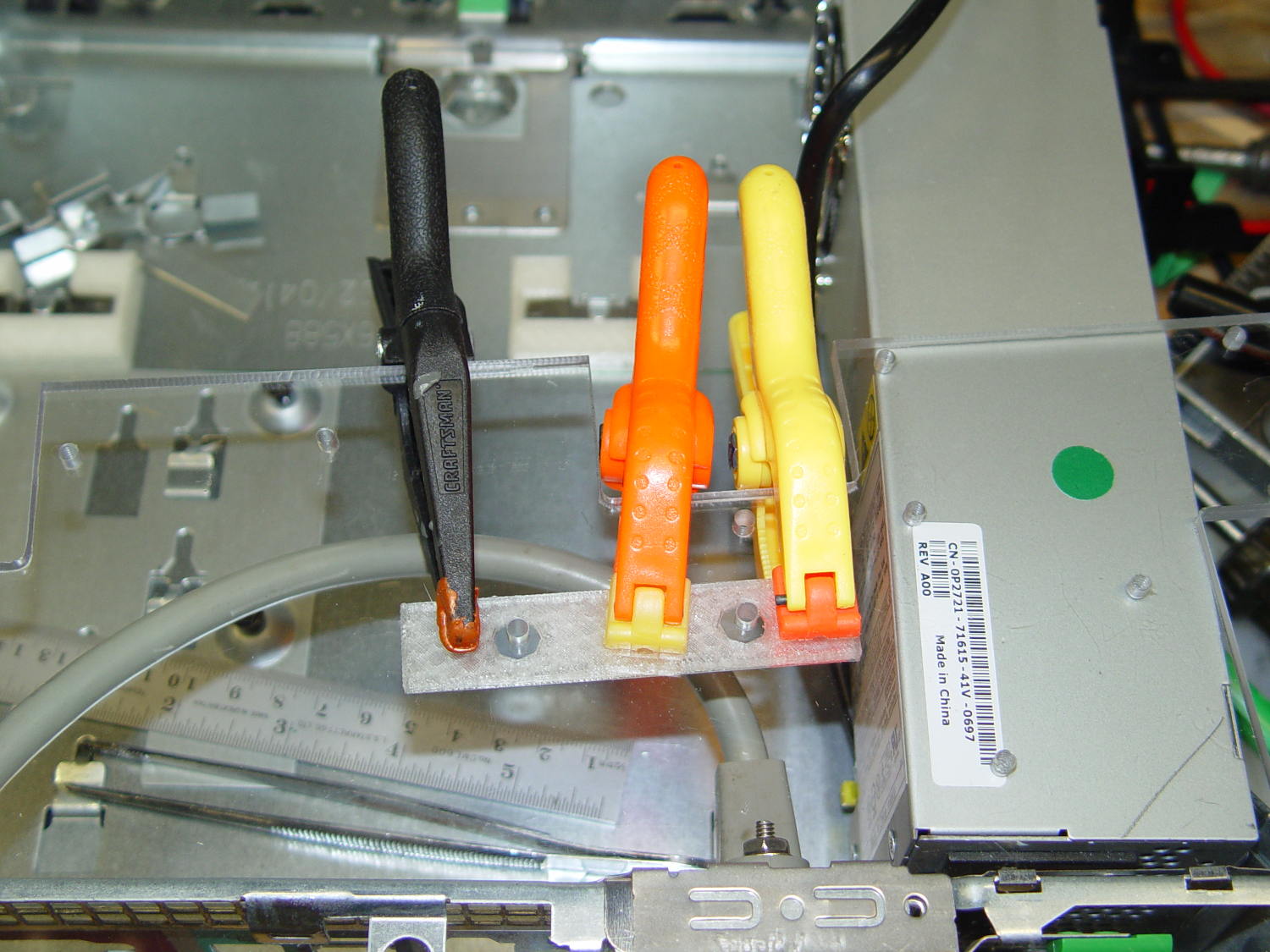
The GX270 case contains a perfectly serviceable ATX power supply that can power all the bits & pieces that don’t run directly from the AC power line. I torched the connector off the system board, but there’s no practical way to mount it standing up through the prototyping board I’m using for the low voltage electronics. This bracket surrounds that connector and holds it at right angles to the board, with a pair of screws clamping it in place:
ATX Connector Bracket – front
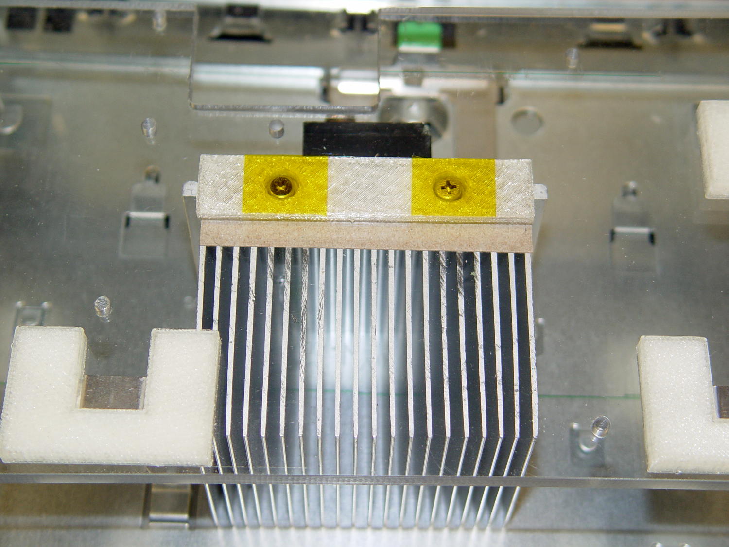
I invoked the shade of Willy McCoy, slashed the outside of the connector with a razor knife, buttered it up with epoxy, and shoved it flush inside the adapter. That messy epoxy bead around the joint should prevent it from pulling out to the front:
ATX Connector Bracket – rear
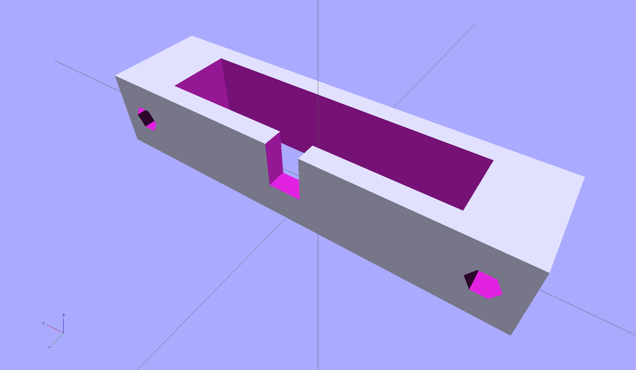
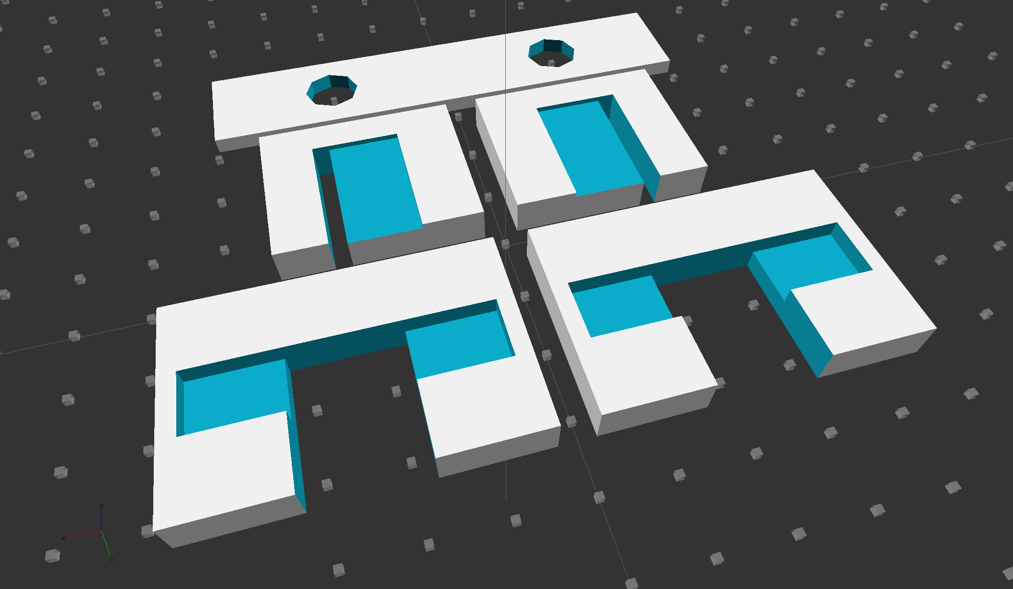
The solid model looks like you’d expect:
ATX Connector Mount
In the unlikely event you need one, make sure the slot clears the locking clip on your ATX connector, as they differ between (at least) the 20 and 24 pin versions. This is actually a split 20/24 connector, with the smaller connector terminating elsewhere to power the LED strips.
Mary finished out the National Bike Challenge with a rank of 3353 of 47 k riders, which, by my reckoning, is wonderfully good. She’s #1 in the Poughkeepsie area (admittedly, of only eight riders), with the second-place rider at 90% of her point score.
She did it by riding on her usual missions, along our usual routes, around the usual obstacles:
NYS Rt 376 at Westview Terrace
Her bike odometer recently rolled past 20 k miles; at least one battery change stole a pile o’ miles from her total, so the bike has accumulated more than that.
As the song goes, my gal is red hot… in the best way!
The Dell GX270 chassis has a small support plate under the CPU, evidently to support the heatsink and fan:
Optiplex GX270 CPU heatsink mount
It slides neatly into those clips on the system board tray, but it’s not actually locked into position. I think that allows it to slide around a bit under the system board, providing vertical support without constraining the board’s horizontal position. Anyhow, it looked like the easiest way to support the prototyping board that will hold the low voltage interface circuitry.
By some mischance, I found a nice aluminum plate exactly the right width, so only one side needed a saw cut and squaring. Coordinate drilling four #6 clearance holes matched the support:
LV Interface Adapter Plate – drilling
That corner of the tray had another system board retaining clip, but rather than bashing it flat, I just sawed a slit in the plate so it can slide right into position. Note the perfect alignment of that screw hole:
LV Interface Adapter Plate – retainer
I love it when all my mistakes cancel out!
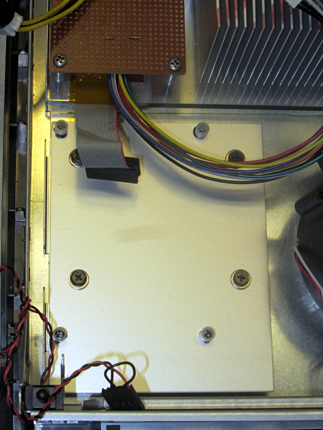
Four more holes matched the prototyping circuit board and, while I had some epoxy mixed up for another part, I fastened four standoffs over the holes. A washer under each original screw soaked up exactly enough space that the screws barely indented the case and, as if by magic, hold the support plate firmly in place:
LV Interface Adapter Plate – installed
Of course, that means I must remove the circuit board to get the tray out, but the AC interface board must also come out, so we’re not talking a spur-of-the-moment operation.
The switch in the lower left corner is the original Dell “intrusion monitoring” switch harvested from a complex metal stamping in the diagonally opposite corner of the case. It’s epoxied to the case wall, with the plunger contacting a shim epoxied to the top of the case, and will eventually disconnect the AC line power from the drive electronics: case open = switch closed = lethal power off.
Back in the day, heatsinks like this sat atop Moah Powah Pentium CPUs:
ET227 transistor on heatsink
I picked it because the hulking ET227 transistor fit neatly on its backside, it seemed capable of handling 30 to 50 W of power, and I have several of them in the Big Box o’ Heatsinks. No careful thermal analysis was involved…
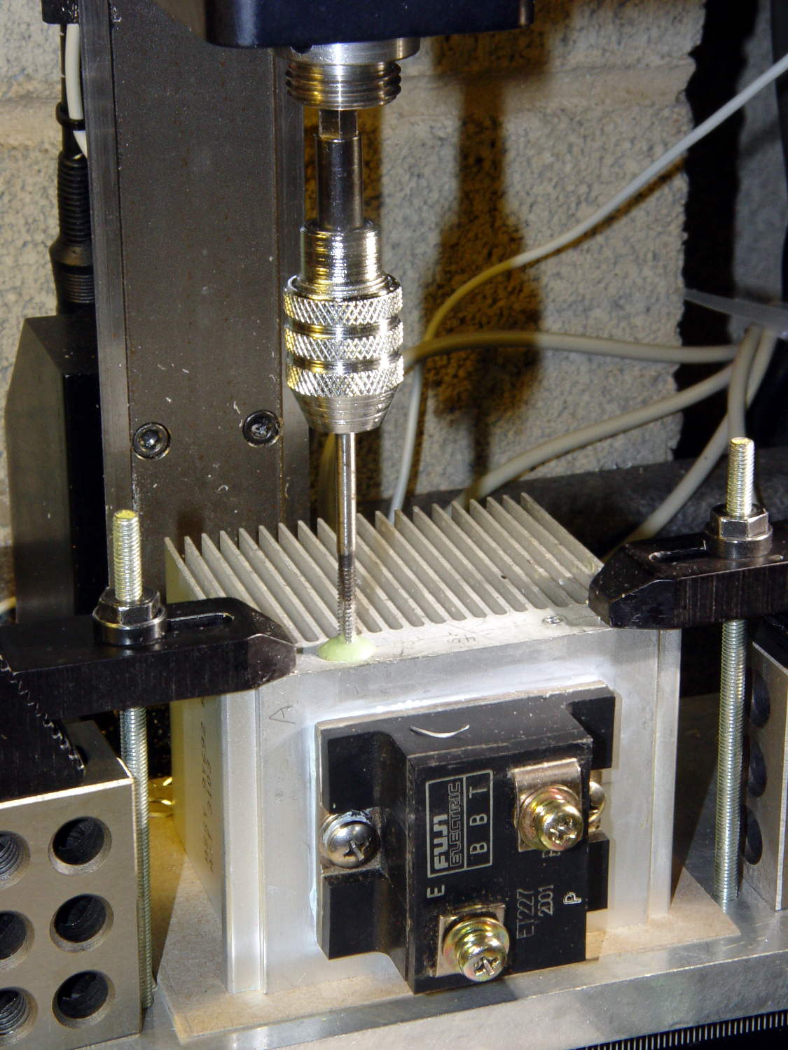
Mounting it on the polycarbonate sheet inside the repurposed GX270 case involved drilling & tapping a pair of 6-32 holes in one side:
ET227 Heatsink – tapping
That’s not rigid tapping on a Sherline, it’s aligning a hand-turned tap in the spindle bore. Sorry.
And, yeah, you’re not supposed to leave the semiconductors mounted when you’re drilling the heatsink. I figure there’s nothing I can possibly do without using a hammer that will bother that transistor in the slightest. What, me worry?
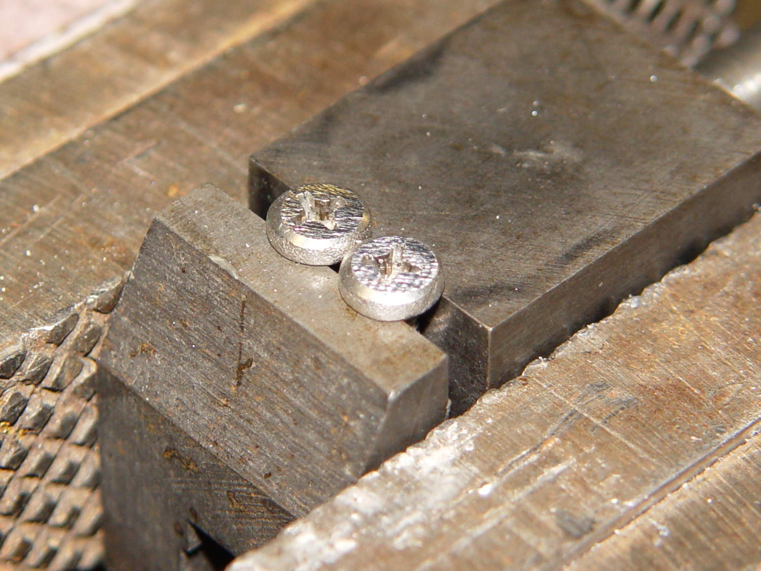
The transistor collector runs at line voltage, which means the entire heatsink will pose a lethal shock hazard. I thought about isolating the collector and failed to come up with anything I’d trust to be both thermally conductive and electrically insulating over the long term; the screw heads must be isolated from the collector plate, too.
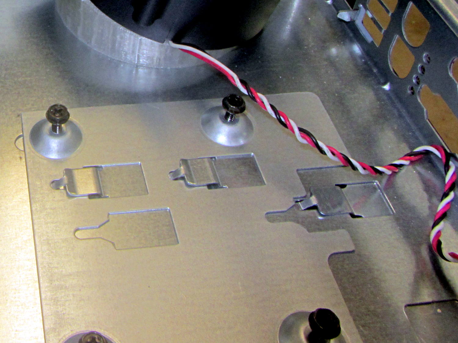
The screws stick out below the polycarbonate sheet, just above the grounded EMI shell lining the case, so I flattened them a bit:
ET227 Heatsink – mounting screws
The simple rectangular strip to the rear of the chassis mounting clips is just slightly thicker than the screw heads, so they can’t possibly contact the case:
Chassis Clips
It gets glued to the underside of the nearly invisible sheet:
ET227 heatsink – gluing screw shield
With Kapton tape over the heads, Just In Case:
ET227 Heatsink – mounted
It makes a nice linear counterpoint to the jumble of AC interface wiring:
AC Interface Chassis
The insulating sheet on the case lid came from the bottom of the original GX270 system board, where I think it served much the same purpose. It’s surely not rated for AC line voltages, but the thought must count for something:
The corn cob sat on the patio after an outdoor supper, awaiting a trip to the trash can, when an all-black woolly bear caterpillar appeared from nowhere.
I’m sure it’s a direct descendant of that one. We put this one in the garden, too, for the same reason.