Ed Nisley's Blog: Shop notes, electronics, firmware, machinery, 3D printing, laser cuttery, and curiosities. Contents: 100% human thinking, 0% AI slop.
The nice countertop and sinks look like obvious replacements since they built this rest area on the NYS Northway up near Saratoga. Unlike the old sinks, however the countertop needed support struts to prevent the backsplash from peeling off the wall when somebody leans on the edge and those struts required planks to make the spacing work out:
NYS Northway Rest Room – Sink Supports
Too bad about that strut right where the drain cleanout plug emerges from the wall. Also too bad that the elaborate welded square doesn’t rest on the wall, so it’s not really supporting anything. Triply too bad about the trim plate that used to conceal the plug; the one that didn’t fit behind the square.
Also: why do the sink drains have such a long horizontal run between the drain tailpiece and the trap? Maybe that’s so they can retrieve rings and other valuables that go down the drain? Perhaps the other trap orientation would put the joint too far forward, where it can be dislodged by an errant knee?
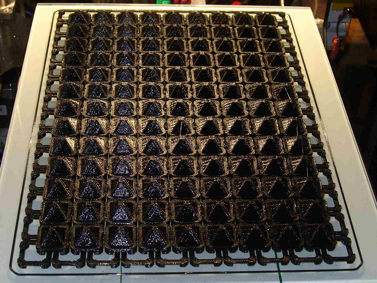
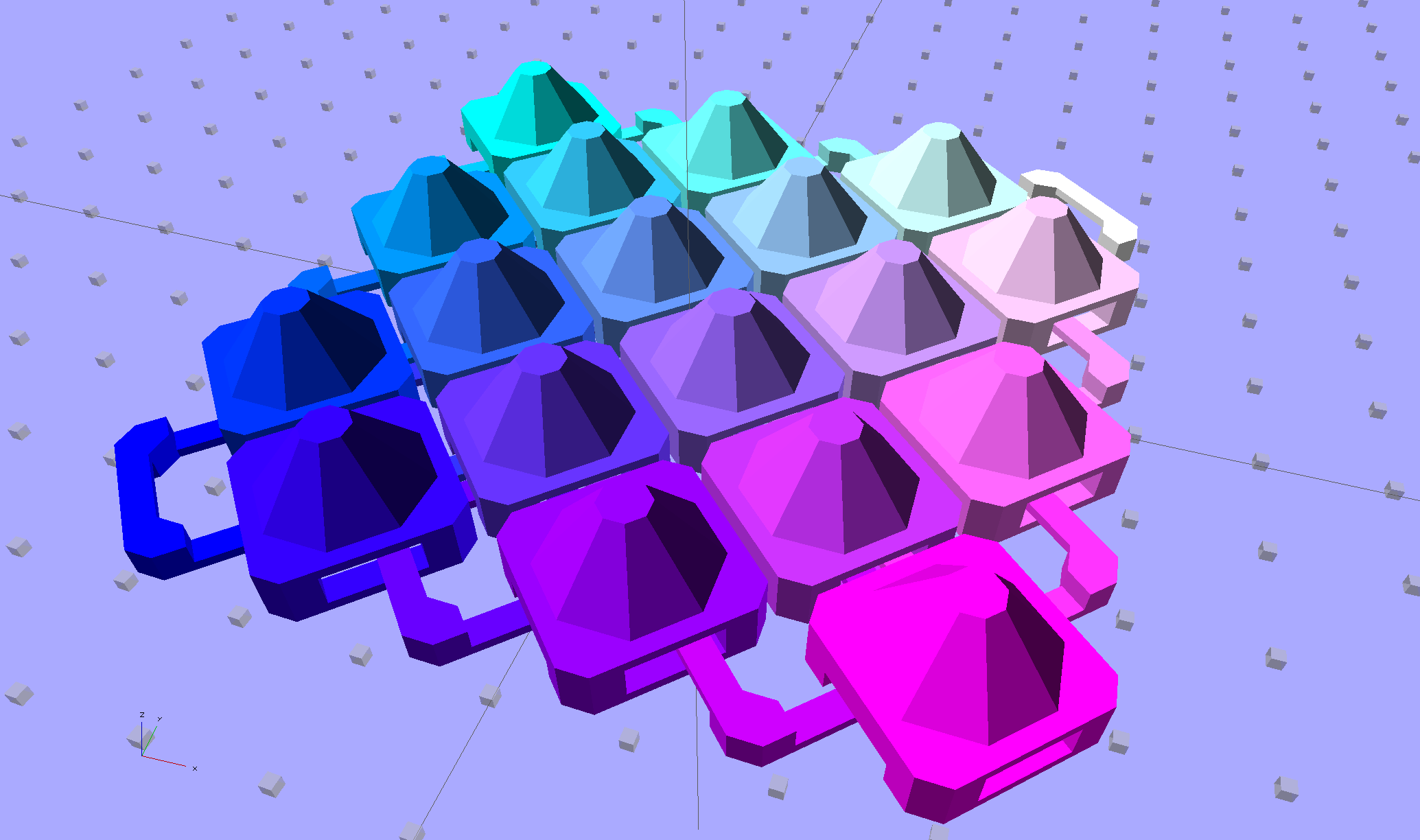
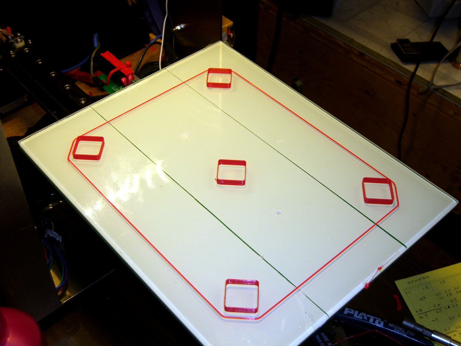
So, with the change of two parameters, the OpenSCAD program can model a 170×230 mm sheet:
Chain Mail Armor – Full Platform Sheet
That works out to a 9×13 array of 117 armor buttons sitting amid 140 connecting links, with two threads = 0.8 mm between adjacent links.
It’s quite imposing in black PLA:
Chain Mail Armor Buttons – full sheet on platform
The skirt thickness varies from 0.15 mm in the X-Y+ corner to 0.25 mm at X+Y-. That’s so close I’m not even tempted to adjust the screws.
As before, all those links pop off right the cool platform without any fuss; the joints had good clearance, the bridges worked, and nothing required post-processing:
Chain Mail Armor Buttons – full sheet folded
You can’t make this through subtractive machining. You can’t make it using molding, either, because the links have barely a sliver of air on all sides: there’s no room for the mold and no way to extract the sheet of links. You could, I suppose, use lost-wax / lost-plastic casting, but cutting the sprue and vent off every link would get really tedious really fast.
Of course, you’re looking at a 5 MB STL file, 22 MB of G-Code, nine continuous hours of printing, and 120 grams of PLA: it’s the largest “single” object I’ve ever printed…
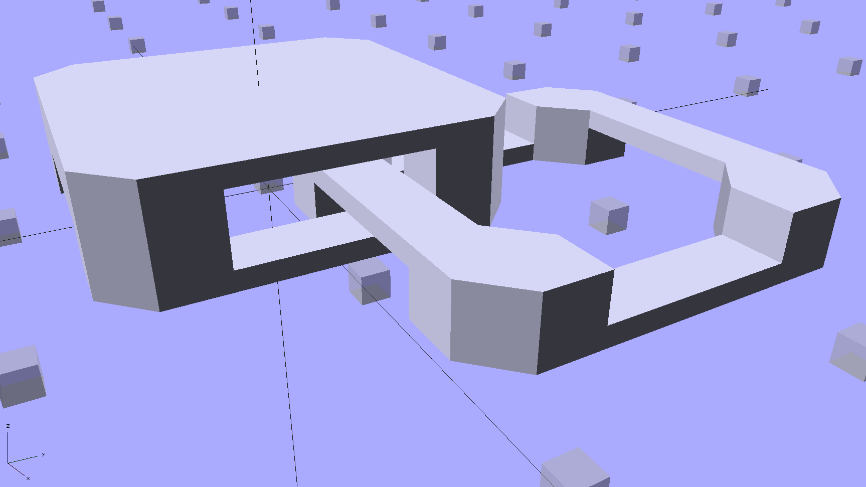
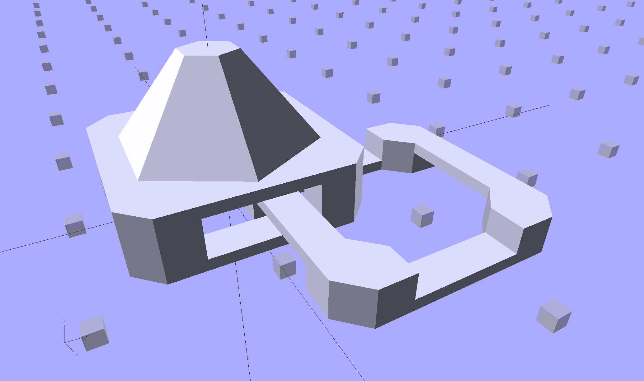
Starting from the improved chain mail link design, extend the top bars enough to clear the cross links, then bridge across them to form a flat cap:
Chain Mail – Armor and Link
The OpenSCAD code makes the links as small as they can possibly be, based on the bar size and clearances, then rounds up to a multiple of the thread width so the flat cap will fill properly. Given the extrusion thread dimensions and the bar sizes, the OpenSCAD code computes everything else: the link model matches the slicer settings that define the printer’s output.
Given:
Thread: 0.4 mm wide x 0.2 mm thick
Bar: 6 thread wide x 4 thread thick = 2.4 x 0.8 mm
Clearances: 2 thread horizontal x 5 thread vertical = 0.8 x 1.0 mm
All the links measure 15.6 mm from side to side, the short connecting links are 2.6 mm tall, and the flat caps are 4.4 mm tall. Interlinked links sit 8.2 mm on center = half the link side plus one thread width clearance, which is 16.4 mm on center for adjacent links.
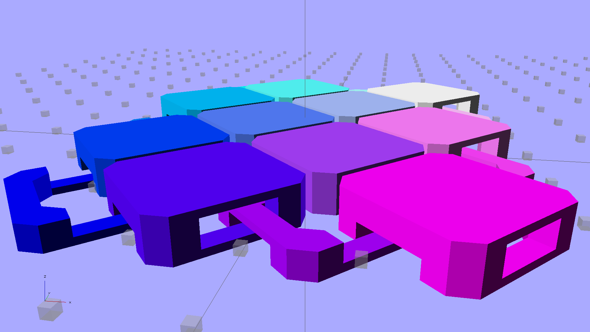
Duplicated appropriately, the caps resemble turtle armor:
Chain Mail – Flat Armor
Which look about the same in real life, minus the cheerful colors:
Armor Buttons – on platform – side
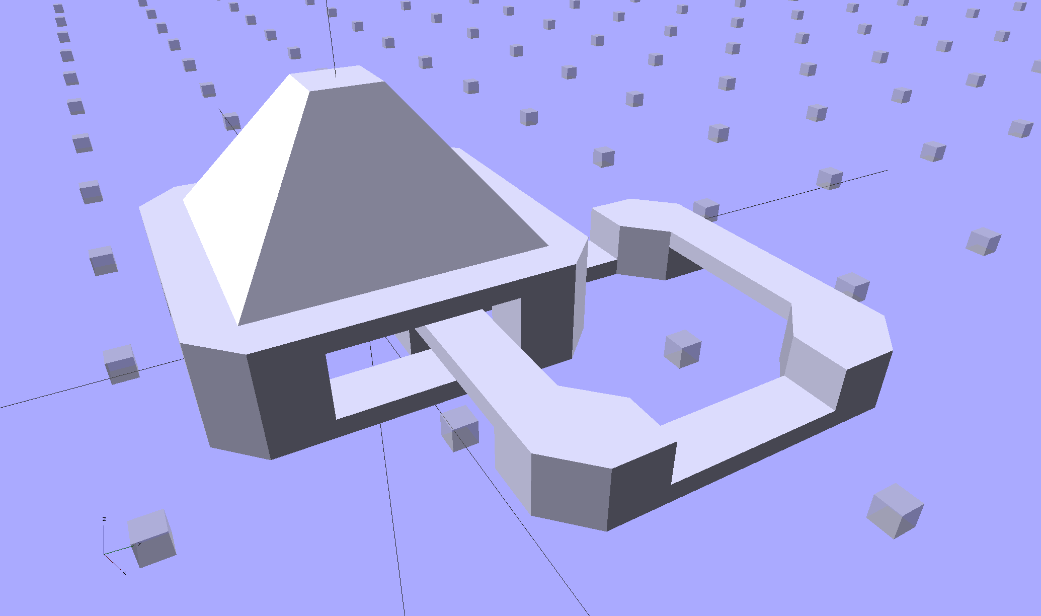
Now, however, you can plunk an armor button atop the cap:
Chain Mail Armor – 4 sided
With any number of sides:
Chain Mail Armor – 6 sided
Up to a truncated cone:
Chain Mail Armor – 24 sided
The flat tip makes the button more durable and user-friendly, but you can make it a bit more pointy if you favor that sort of thing. The button adds 6 mm to the link base, making armor links 10.4 mm tall.
Other printable stuff could fit on that cap: letters, decorations, widgets, whatever.
I think square armor buttons look ever so imposing when they’re arrayed in a sheet:
Chain Mail Armor – square – 4 sided
The general idea being that you could attach the armor sheet to a cloth / leather backing to form a gauntlet or greave; the border of bottom links around the button array should serve for that purpose.
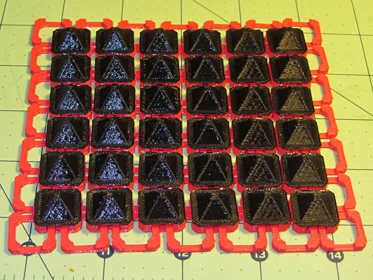
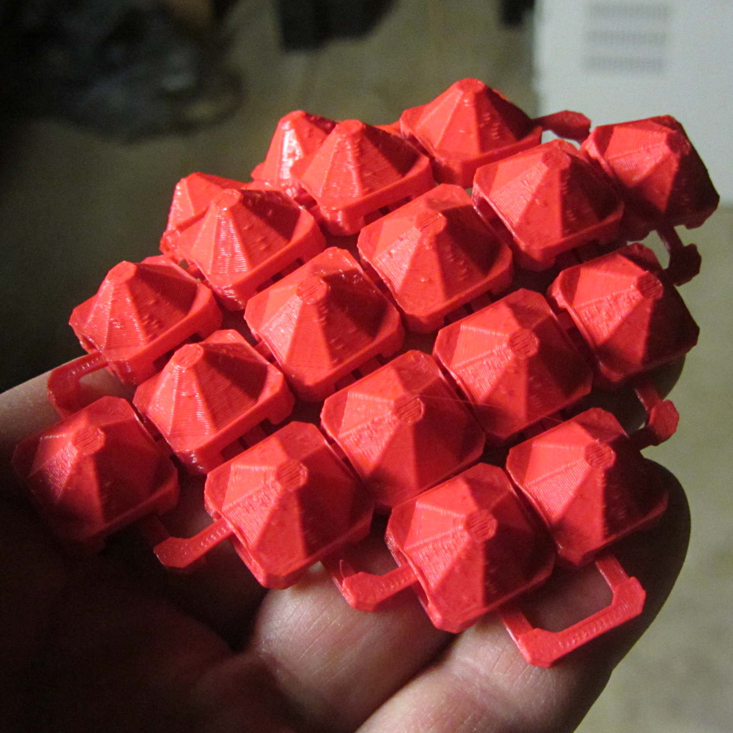
The plastic prints just like the model and pops off the M2’s platform ready to use, with no finishing required:
Chain Mail Armor – square on desk
The two-color effect came from hot-swapping black filament as the red PLA ran out. The 6×6 armor button array and the 7×7 connecting link array holding it together required 14 meters of filament and I guesstimated the red spool held 9 meters: I was ready when the last of the red vanished just after completing the bridging layer under the flat caps. Filament swaps work reasonably well; I’d hate to do that on a production basis.
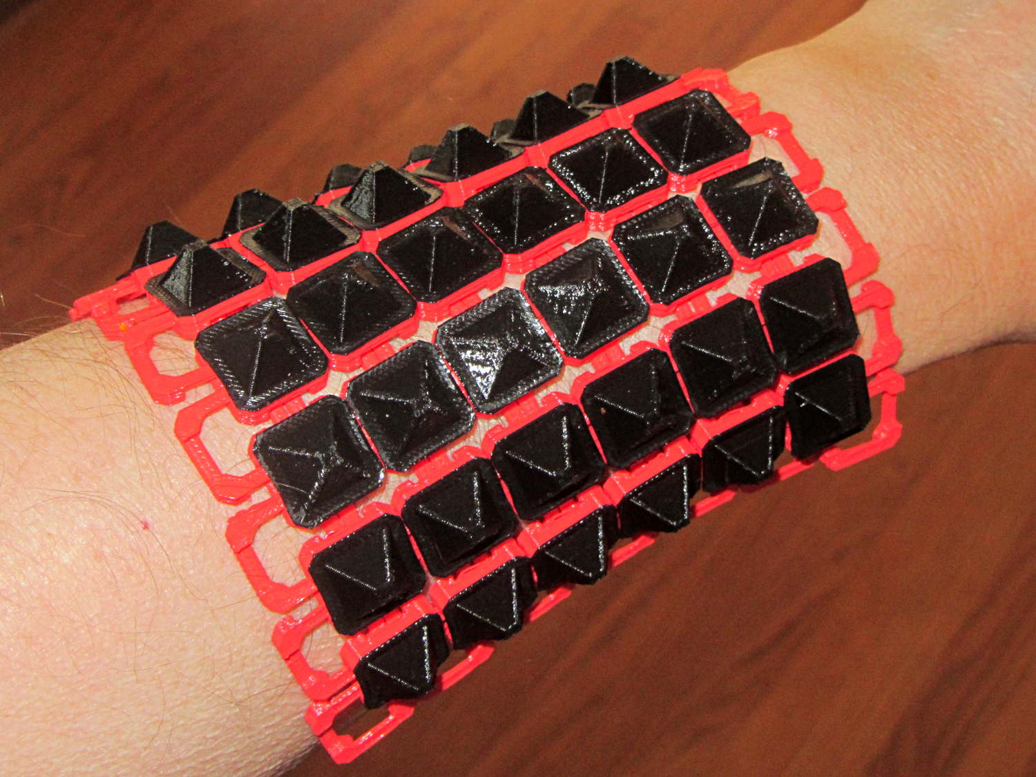
If you don’t mind my saying so, everybody thinks it’s spectacular:
Chain Mail Armor – square on arm
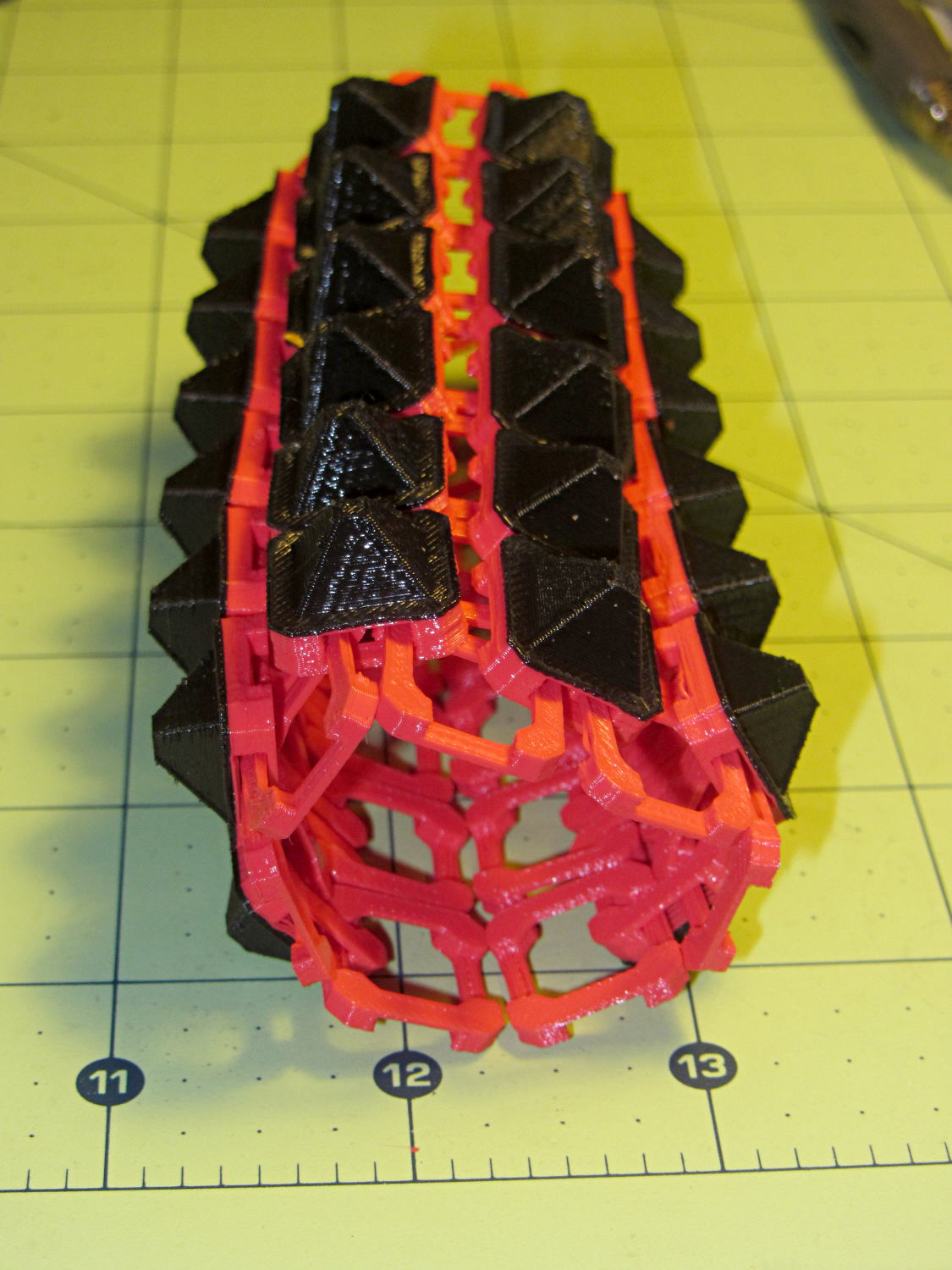
The sheet has a definite “grain” defined by the orientation of the bottom links, making it far more bendy in one direction than the other:
Chain Mail Armor – square rolled
The sheet layout orients the more-bendy direction along the M2’s (longer) Y axis, so that sheets can wrap snugly around your arm (or leg) and extend straight-ish along the bones in the other direction. That should be configurable, I think.
There’s an option to rotate the links by 45° to produce diamond-theme arrays:
Chain Mail Armor – diamond – 8 sided
Which would make good patch armor, if you’re into that sort of thing:
Chain Mail Armor – diamond on hand
Those have octagonal buttons, which IMHO don’t look nearly as crisp as the four-sided version.
Ah! I should generalize the diamond rotation option to select all four useful rotations.
The 6×6 square sheet requires three hours on the M2, with the intial print time estimates being low by nearly a factor of two. The M2 has a 200×250 mm platform and I’ll definitely try a full-size array just to see how it works.
The OpenSCAD source code, which stands badly in need of refactoring:
// Chain Mail Armor Buttons
// Ed Nisley KE4ZNU - November 2014

Layout = "Build";			// Link Button LB Build

//-------
//- Extrusion parameters must match reality!
//  Print with 1 shell and 2+2 solid layers

ThreadThick = 0.20;
ThreadWidth = 0.40;

HoleWindage = 0.2;

Protrusion = 0.1;			// make holes end cleanly

function IntegerMultiple(Size,Unit) = Unit * ceil(Size / Unit);

//-------
// Dimensions

//- Set maximum sheet size

SheetSizeX = 70;
SheetSizeY = 80;

//- Diamond or rectangular sheet?

Diamond = false;					// true = rotate 45 degrees, false = 0 degrees for square
ArmorButton = true;					// true = build button atop cap

// Link bar sizes

BarWidth = 6 * ThreadWidth;
BarThick = 4 * ThreadThick;

BarClearance = 5*ThreadThick;		// vertical clearance above & below bars

//-- Compute link sizes from those values

// Absolute minimum base link: bar width + corner angle + build clearance around bars
//  rounded up to multiple of thread width to ensure clean filling
BaseSide = IntegerMultiple((4*BarWidth + 2*BarWidth/sqrt(2) + 3*(2*ThreadWidth)),ThreadWidth);

BaseHeight = 2*BarThick + BarClearance;           // both bars + clearance

echo(str("BaseSide: ",BaseSide," BaseHeight: ",BaseHeight));

BaseOutDiagonal = BaseSide*sqrt(2) - BarWidth;
BaseInDiagonal = BaseSide*sqrt(2) - 2*(BarWidth/2 + BarWidth*sqrt(2));

echo(str("Outside diagonal: ",BaseOutDiagonal));

//- On-center distance measured along coordinate axis

LinkOC = BaseSide/2 + ThreadWidth;

LinkSpacing = Diamond ? (sqrt(2)*LinkOC) : LinkOC;
echo(str("Base spacing: ",LinkSpacing));

//- Compute how many links fit in sheet

MinLinksX = ceil((SheetSizeX - (Diamond ? BaseOutDiagonal : BaseSide)) / LinkSpacing);
MinLinksY = ceil((SheetSizeY - (Diamond ? BaseOutDiagonal : BaseSide)) / LinkSpacing);
echo(str("MinLinks X: ",MinLinksX," Y: ",MinLinksY));

NumLinksX = ((0 == (MinLinksX % 2)) && !Diamond) ? MinLinksX + 1 : MinLinksX;
NumLinksY = ((0 == (MinLinksY % 2) && !Diamond)) ? MinLinksY + 1 : MinLinksY;
echo(str("Links X: ",NumLinksX," Y: ",NumLinksY," Total: ",NumLinksX*NumLinksY));

//- Armor button base

CapThick = BarThick;

ButtonHeight = BaseHeight + BarClearance + CapThick;
echo(str("ButtonHeight: ",ButtonHeight));

//- Armor ornament size & shape

ArmorSides = 4;
ArmorAngle = true ? 180/ArmorSides : 0;			// rotate half a side?

ArmorThick = IntegerMultiple(6,ThreadThick);	// keep it relatively short

ArmorOD = 1.1 * BaseSide;						// tune for best fit at base

ArmorID = 10 * ThreadWidth;						// make the tip wide & strong

//-------

module ShowPegGrid(Space = 10.0,Size = 1.0) {

  RangeX = floor(95 / Space);
  RangeY = floor(125 / Space);

	for (x=[-RangeX:RangeX])
	  for (y=[-RangeY:RangeY])
		translate([x*Space,y*Space,Size/2])
		  %cube(Size,center=true);

}

//-------
// Create base link

module BaseLink() {

render()
	rotate(Diamond ? 45 : 90)			// 90 = more bendy around X axis
		difference() {
			translate([0,0,BaseHeight/2]) {
				difference(convexity=2) {
					intersection() {		// outside shape
						cube([BaseSide,BaseSide,BaseHeight],center=true);
						rotate(45)
							cube([BaseOutDiagonal,BaseOutDiagonal,BaseHeight],center=true);
					}
					intersection() {		// inside shape
						cube([(BaseSide - 2*BarWidth),
							  (BaseSide - 2*BarWidth),
							  (BaseHeight + 2*Protrusion)],
							 center=true);
						rotate(45)
							cube([BaseInDiagonal,
								  BaseInDiagonal,
								  (BaseHeight +2*Protrusion)],
								 center=true);
					}
				}
			}

			translate([0,0,(BaseHeight/2 + BarThick)])
				cube([(BaseSide - 2*BarWidth - 2*BarWidth/sqrt(2)),
					  (2*BaseSide),
					  BaseHeight],
					 center=true);
			translate([0,0,(BaseHeight - BaseHeight/2 - BarThick)])
				cube([(2*BaseSide),
					  (BaseSide - 2*BarWidth - 2*BarWidth/sqrt(2)),
					  BaseHeight],
					 center=true);
		}
}

//-------
// Create button link

module ButtonLink() {

render()
	rotate(Diamond ? 45 : 90)			// 90 = more bendy around X axis
		union() {
			difference() {
				translate([0,0,ButtonHeight/2])		// outside shape
					intersection() {
						cube([BaseSide,BaseSide,ButtonHeight],center=true);
						rotate(45)
							cube([BaseOutDiagonal,BaseOutDiagonal,ButtonHeight],center=true);
					}
				translate([0,0,(BaseHeight + BarClearance - Protrusion)/2])
					intersection() {		// inside shape
						cube([(BaseSide - 2*BarWidth),
								(BaseSide - 2*BarWidth),
								(BaseHeight + BarClearance + Protrusion)],
								center=true);
						rotate(45)
							cube([BaseInDiagonal,
									BaseInDiagonal,
									(BaseHeight + BarClearance + Protrusion)],
									center=true);
				}

				translate([0,0,((BarThick + 2*BarClearance)/2 + BarThick)])
					cube([(BaseSide - 2*BarWidth - 2*BarWidth/sqrt(2)),
						(2*BaseSide),
						BarThick + 2*BarClearance],
						center=true);

				translate([0,0,(BaseHeight/2 - BarThick)])
					cube([(2*BaseSide),
						(BaseSide - 2*BarWidth - 2*BarWidth/sqrt(2)),
						BaseHeight],
						center=true);

			}

			if (ArmorButton)
				translate([0,0,(ButtonHeight - Protrusion)])		// armor on cap
					rotate(ArmorAngle)
					cylinder(d1=ArmorOD,
							 d2=ArmorID,
							 h=(ArmorThick + Protrusion),
							 $fn=ArmorSides);
		}
}

//-------
// Build it!

ShowPegGrid();

if (Layout == "Link") {
	BaseLink();
}

if (Layout == "Button") {
	ButtonLink();
}

if (Layout == "LB") {
	ButtonLink();
	translate([LinkSpacing,LinkSpacing,0])
		BaseLink();
}

if (Layout == "Build") {
	for (ix = [0:(NumLinksX - 1)],
		 iy = [0:(NumLinksY - 1)])
			assign(x = (ix - (NumLinksX - 1)/2)*LinkSpacing,
				   y = (iy - (NumLinksY - 1)/2)*LinkSpacing)
			translate([x,y,0])
			color([(ix/(NumLinksX - 1)),(iy/(NumLinksY - 1)),1.0])
				if (Diamond)
					if ((ix + iy) % 2)						// armor at odd,odd & even, even points
						ButtonLink();
					else
						BaseLink();							// connectors otherwise
				else
					if ((iy % 2) && (ix % 2))				// armor at odd,odd points
						ButtonLink();
					else if ((!(iy % 2) && !(ix % 2)))		// connectors at even,even points
						BaseLink();
}
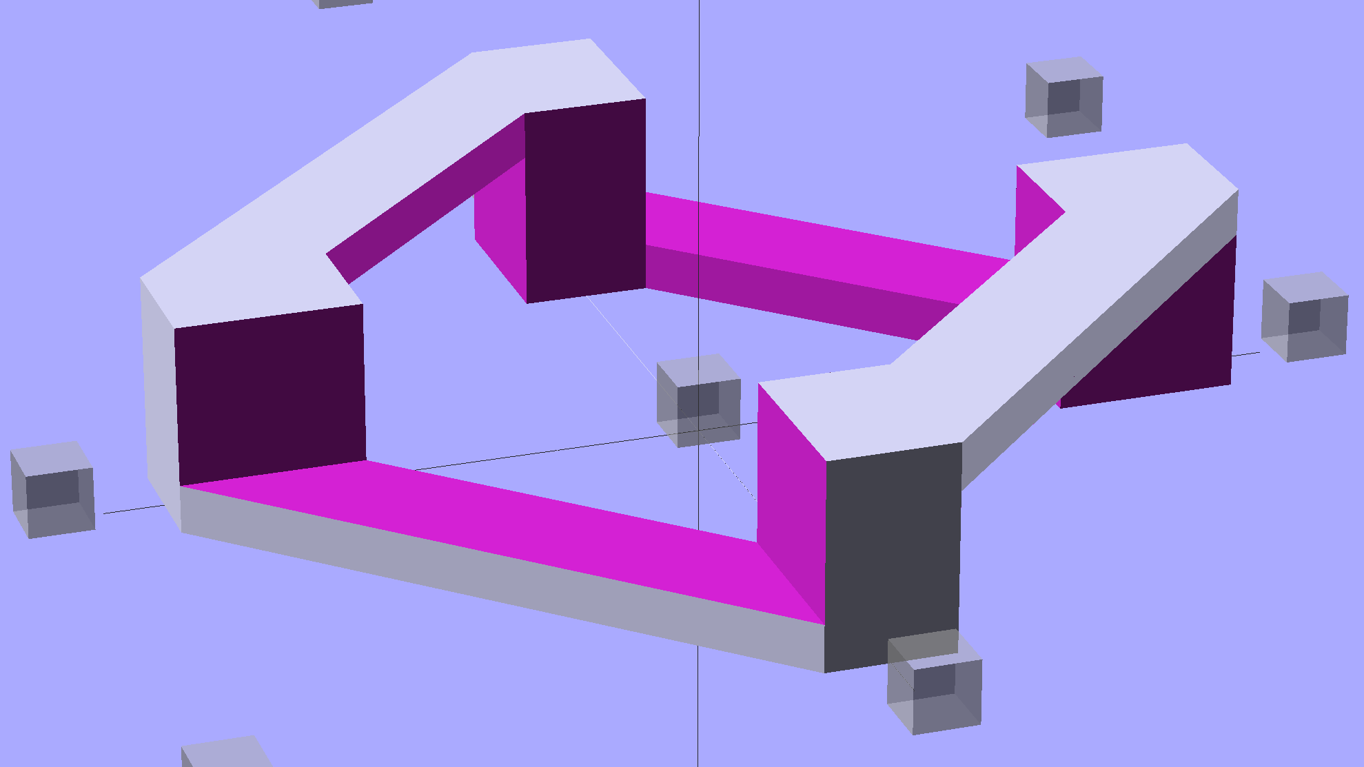
The rectangular posts in my chain mail resemble Zomboe’s original design, but with dimensions computed directly from the bar (and, thus, thread) widths and thicknesses to ensure good fill and simple bridging:
Chain Mail Link
They fit together well, but the angled post edges make the bridge threads longer than absolutely necessary along the outside edge of each link:
Chain Mail Sheet – detail
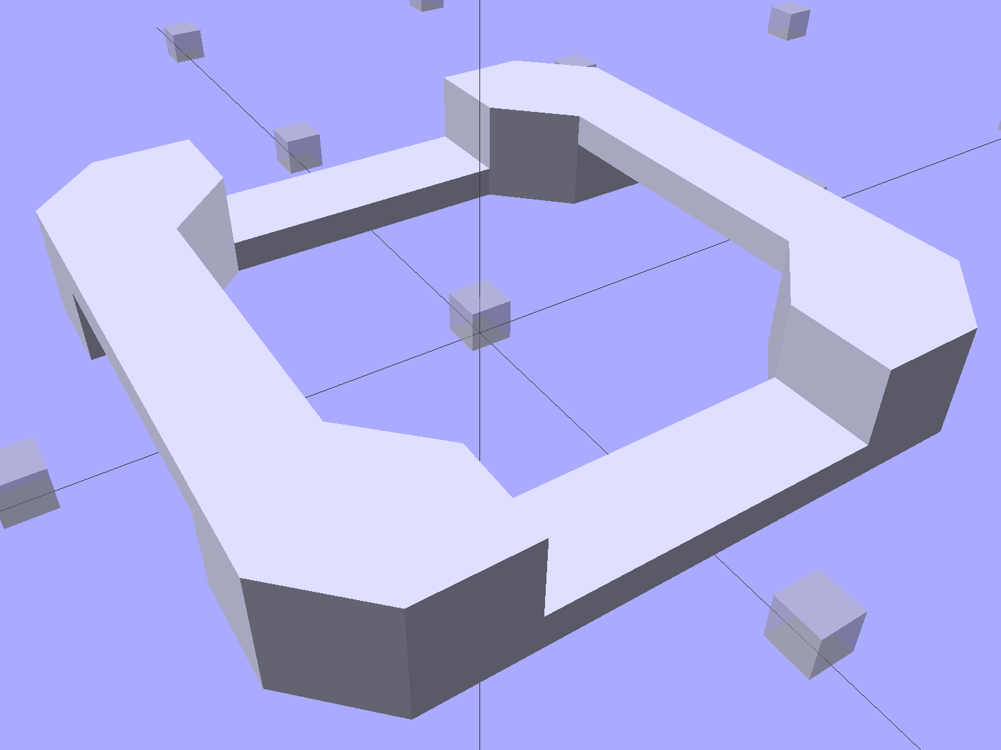
A bit of fiddling produces a squared-off version:
Chain Mail Link – Improved Posts
Which nest together like this:
Chain Mail – Improved Posts – Bottom View
Now all the bridge threads have the same length, which should produce better results.
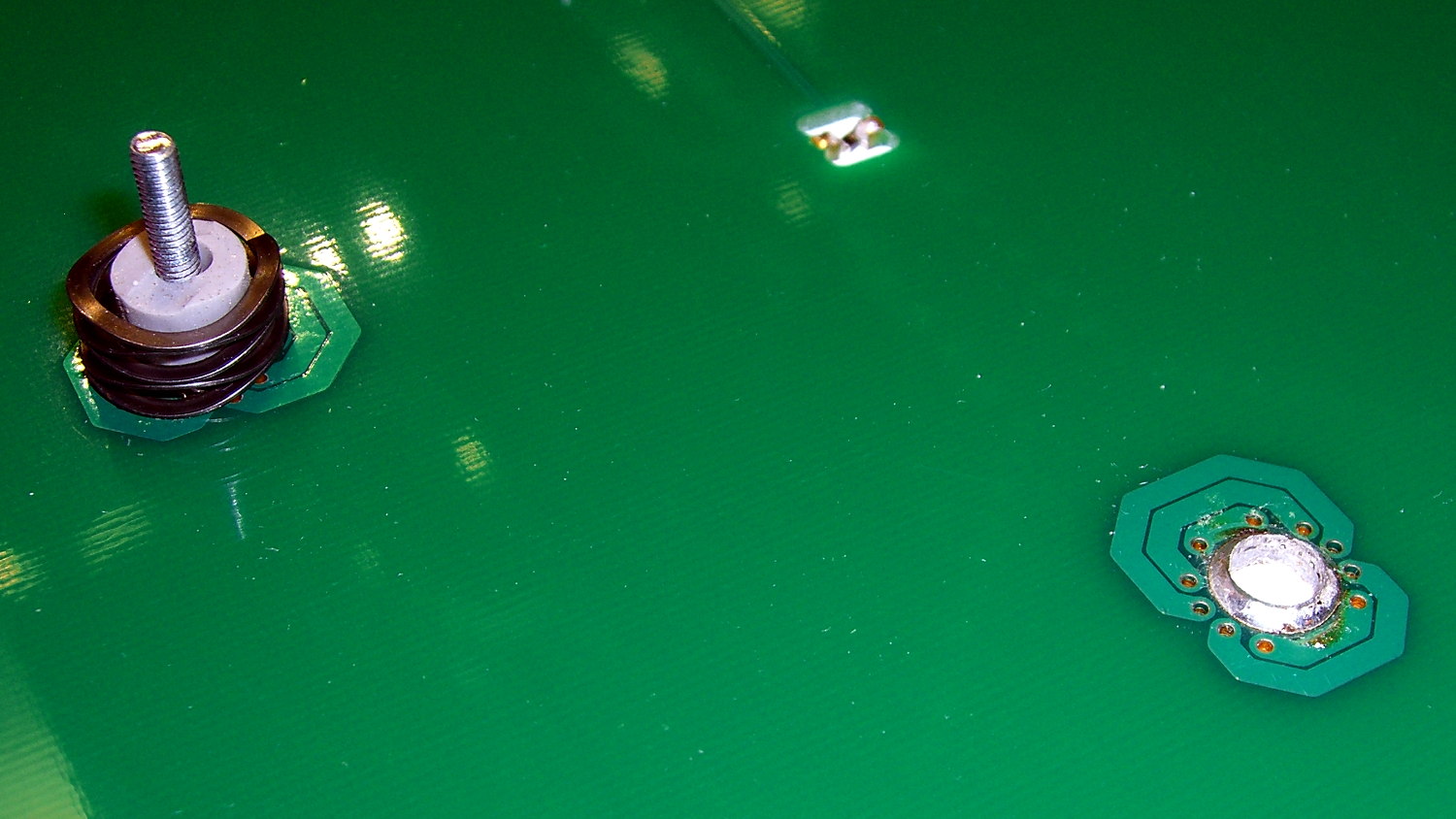
The hotrod build platform I’m using with the Makergear M2 consists of a PCB heater bonded to a glass plate, supported by three socket head cap screws soldered into the PCB. The print quality recently took a nosedive that seemed related to the first layer height, with which I fiddled more than usual, and finally the front of the platform became obviously, visibly, no-way-around-it far too high. Peering under the platform showed that the front support stud had pulled out of the solder fillet securing it to the PCB:
M2 Hotrod Platform – support stud pullout
Those PCB patterns conduct the heater current around the mounting holes: the hotrod platform has better heat distribution than the OEM M2 platform.
The offending screw didn’t go anywhere:
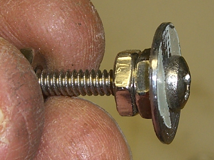
M2 Hotrod Platform – support stud in spring
The wavy spring and silicone plug press on the PCB, so the solder fillet had to support all the stress. It seemed as though the solder hadn’t bonded to the stainless SHCS, but, rather than try to fix that, I decided to put a washer on the screw. That way, the spring bears on the washer and the screw head supports the strain, with the solder fillet responsible for holding the PCB and glass plate in position.
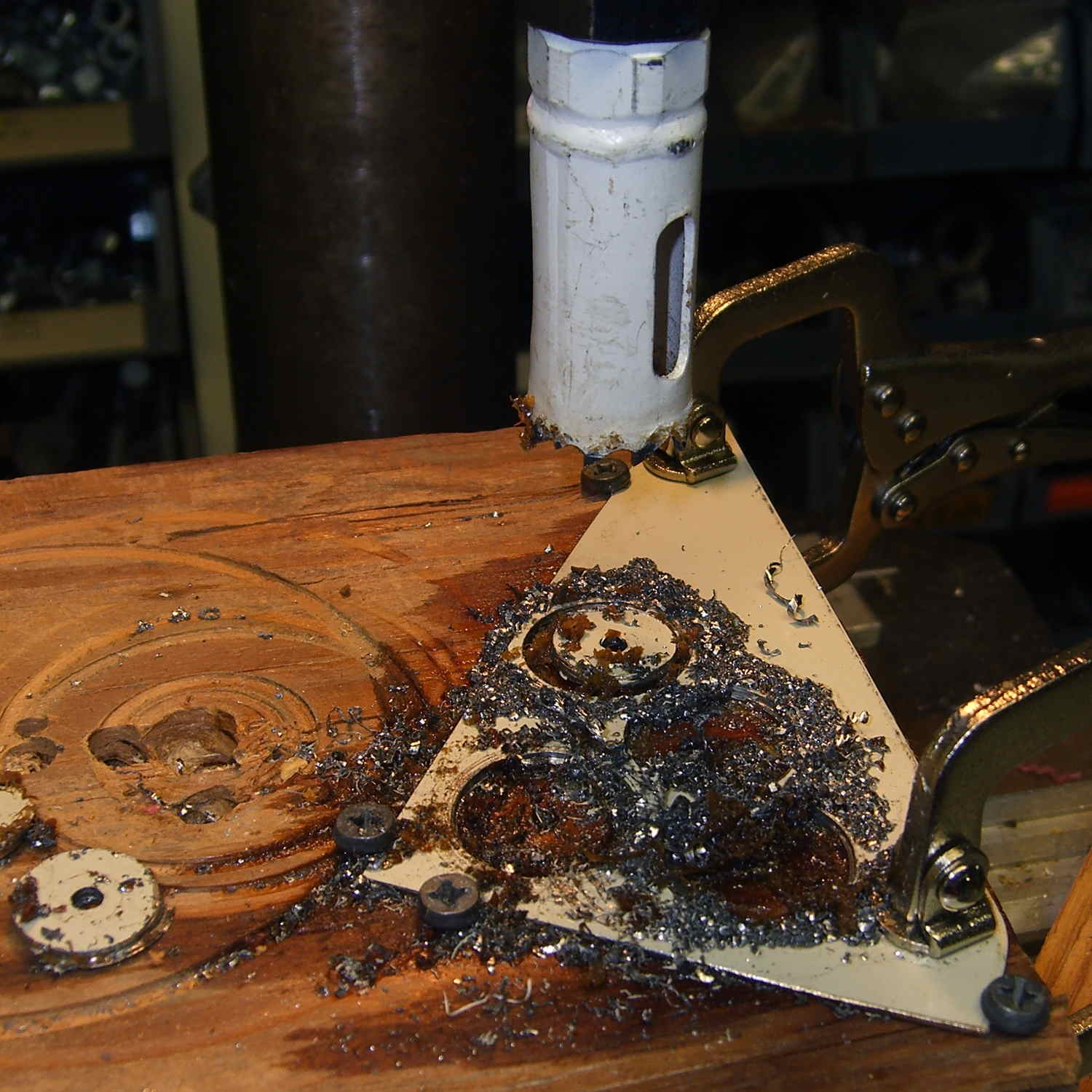
Alas, I didn’t have any washers small enough on the inside (3 mm) and big enough on the outside to support the springs, so I cut some out of a sheet steel scrap by drilling the center hole to the proper diameter, then applying a hole saw without its (far too large) pilot drill:
M2 Hotrod Platform – hole-sawing washers
That’s a lethally bad idea, as the pilot-less saw can grab the sheet and toss it across the shop. Notice the screws holding the sheet down and absorbing the cutting torque, plus the two clamps enforcing the “stay put” edict.
The other problem with not having a pilot drill in the hole saw is that it’s not guaranteed to cut a cookie that’s concentric with the center hole. Instead of taking the time to make a pilot, I just drilled and cut a few extra washers, then picked the best three of the set for finishing:
M2 Hotrod Platform – rough-cut washers
Using a screw as a mandrel, I lathe-turned the OD of the better ones to make them nice and round:
M2 Hotrod Platform – washer on mandrel
Two of the three PCB support screws were in the right place (they hadn’t come loose), so I used the M2 as an alignment fixture for the third:
M2 Hotrod Platform – aligning washers
That’s a layer of good old JB Industro Weld epoxy, rated for much higher temperatures than the platform will ever see, between the big washers and the PCB. I buttered up the head of the errant screw and the inside of the solder fillet, shoved it in, and then stacked everything together. The small washers held the big washers perpendicular to the screws while the epoxy cured.
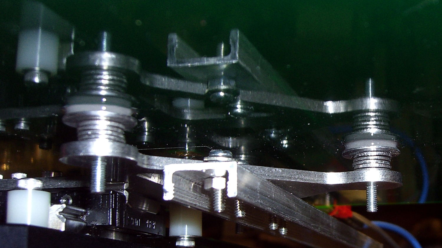
After that, I removed the small washers, reinstalled springs + silicone plugs, tightened the nyloc nuts, aligned the platform, ran off a few thinwall hollow boxes, tweaked the alignment, and it was all good:
M2 Hotrod Platform – thinwall box alignment
The rest of the story: that mumble screw pulled loose on the Friday evening before the Mini Maker Faire on Saturday morning. I did all the shop work after supper, then let the epoxy cure overnight with the platform set to 95 °F while I got a good night’s sleep. Reinstalling and realigning the platform took the better part of half an hour around breakfast, after which I tore it all down, packed it all up, and headed off to the Mini Maker Faire.
In truth, that’s the most trouble I’ve had with the M2 and it’s not Makergear’s fault: it’s not their platform. After reinstalling the platform, the alignment was no big deal and it’s been stable ever since.
It seems the batch of Energizer CR2032 lithium cells I bought a while ago reached the end of their shelf life:
Energizer CR2032 – short life
In point of fact, I replaced three CR2032 cells this month, all with anomalously short lives: one month counts as a complete failure. The Energizer date code YA isn’t helpful in determining when they were manufactured or what the shelf life might be.
Admittedly, I bought that batch in late 2009, so they might have used up most of their shelf life on somebody else’s shelf. There’s no way to know.
It’s not clear one can buy known-good cells from any supplier these days, as the counterfeiters evidently get genuine holograms from the same factory as the Brand Names.