Ed Nisley's Blog: Shop notes, electronics, firmware, machinery, 3D printing, laser cuttery, and curiosities. Contents: 100% human thinking, 0% AI slop.
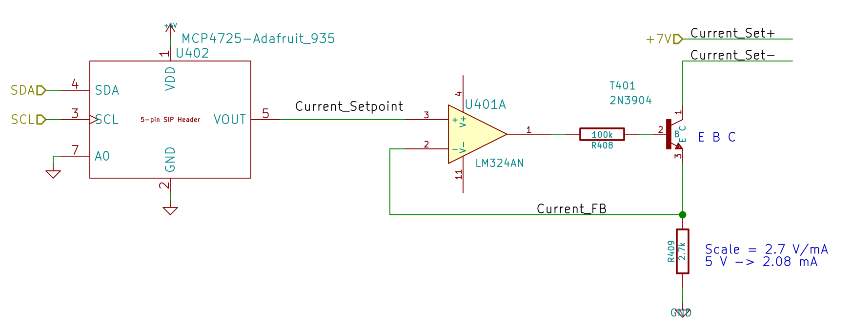
Because the motor will draw more current during pulsed operation, the ET227 needs more base drive. The existing circuit topped out around 2.5 A, so I reduced the current sampling resistor by a bit:
Optoisolator Driver
If you care about the exact current, you’d use a 1% resistor, but if you care about the current, you’ll be doing closed-loop feedback to compensate for the transistor gain variations. Compared to those, the resistor doesn’t matter.
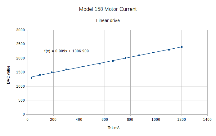
Running the MCP4725 DAC through its range produces a nice graph:
Current Calibrate – DAC – 270k Hall 2.7k opto
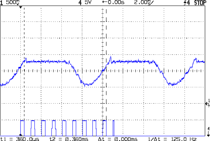
The X axis comes from the Tek Hall-effect current probe, so the numbers don’t depend on the ferrite toroid & differential amp calibration. They do, of course, require a bit of eyeballometric calibration to extract the flat top from the waveform, as shown by this old waveform:
Motor current – ADC sample timing
Ya gotta start somewhere.
The linear fit to those dots gives the DAC value required to produce the observed current, at least for these particular transistors at whatever temperature they’re at in a rather chilly Basement Laboratory.
Of course, the observed current tops out at 1.2 A: the motor’s peak current during normal linear operation. The line looks so pretty that I’ll assume it continues upward to the maximum 12-bit DAC value of 4095 and the corresponding ET227 current. Working backwards, that will be 3.1 A and should suffice for all but the highest peaks at high line voltage.
Reducing the differential amp gain fits a higher current into the Arduino’s fixed 5 V ADC range:
Hall Sensor Differential Amp
Those are 1% resistors, chosen from the heap for being pretty close to what I needed. Given that it’s an LM324 op amp, we’re not talking instrumentation grade results here.
The same calibration run that produced the DAC plot gave these values:
Current Calibrate – ADC – 270k Hall 2.7k opto
The linear fit gives the actual current, as seen by the Tek probe, for a given ADC reading.
The trimpot controls the offset voltage at zero current; working backwards, ADC = 0 corresponds to 140 mV, a bit higher than the actual 90 mV. Close enough, at least for a linear fit to eyeballed data, sez I.
Working forward, the maximum ADC value of 1023 corresponds to 4 A, which should suffice.
Although small power diodes make fine flyback diodes for relays, the motor can draw several amps during the startup pulse, which will be a bit out of spec for the usual 1N4007-class diodes. Pressing an old 5 A / 200 V stud diode into service produces the ungainly black-and-blue lump eating the end of the green wire:
Motor flyback diode – installed
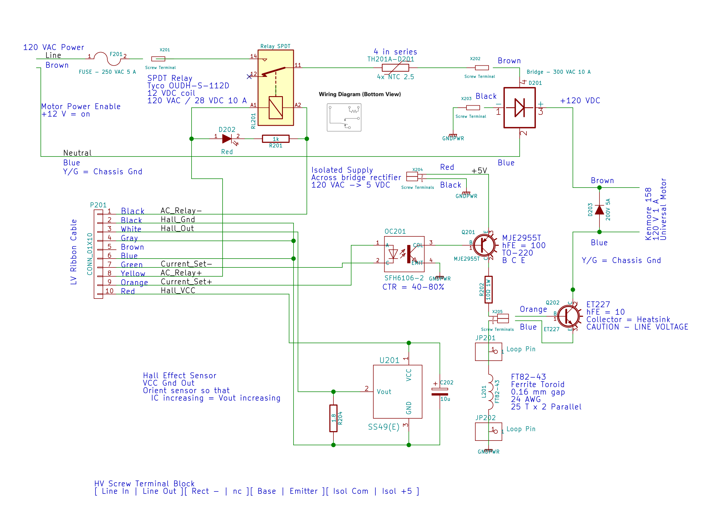
For completeness, here’s the entire AC line interface part of the schematic:
AC Power Interface
The diode’s 200 V limit should suffice, even for cold starts at high line peaks, but, when you build this with new parts, get something rated a bit higher, OK?
A Circuit Cellar reader sent me a lengthy note describing his approach to slow-motion AC motor drives, designed for an already ancient truck mounted radar antenna back in 1972-ish, that prompted me to try it his way.
The general idea is to pulse the motor at full current for half a power line cycle with an SCR (rather than a triac) at a variable pulse repetition rate: the high current pulse ensures that the motor will start turning and the variable repetition frequency determines the average speed. As he puts it, the motor will give off a distinct tick at very low speeds and the maximum speed will depend on how the motor reacts to half-wave drive.
Note that this is not the chopped-current approach to speed control: the SCR always begins conducting at the first positive-going 0 V crossing after the command and continues until the motor current drops to zero. There are no sharp edges generating high-pitched acoustic noise and EMI: silence is golden.
The existing speed control circuitry limits the peak current and assumes that the motor trundles along more-or-less steadily. That won’t be the case when it’s coasting between discontinuous current pulses.
When I first looked at running the motor on DC, these measurements showed the expected relationship:
Kenmore Model 158 AC Motor on DC – Loaded and Unloaded RPM vs Voltage
Eyeballometrically, the slowest useful speed will be 2 stitch/s = 120 shaft RPM = 1300 motor RPM. At that speed, under minimal load, the motor runs on about 20 V and draws 550 mA. At that current, the 40 Ω winding drops 22 V, which we’ll define as “about 20 V” for this discussion, so the back EMF amounts to pretty nearly zilch.
That’s what you’d expect for the fraction of a second while the motor comes up to full speed, but in this case it never reaches full speed, so the motor current during the pulses will be limited only by the winding resistance. At the 200 V peak I’ve been using for the high-line condition, that’s about 5 A peak, although I’d expect 4 A to be more typical.
So, in order to make this work:
the optocoupler driving the base needs more current
the differential amp from the Hall effect sensor needs less gain
Given the ease with which I’ve pushed the hulking ET227 transistor out of its SOA, the motor definitely needs a flyback diode to direct the winding current away from the collector as the transistor shut off at the end of the pulse. Because it’s running from full-wave rectified AC, the winding current never drops to zero: there will definitely be enough current to wreck the transistor.
The firmware needs reworking to produce discrete pulses at a regular pace, rather than slowly adjusting the current over time, but that’s a simple matter of software…
An unused parking behind Yet Another Abandoned Commercial Building, out on Tucker Drive in Arlington, features this tableau:
Crunched tank truck – overview
A closer look:
Crunched tank truck – detail
Something snagged the tank while the truck backed up and ripped that seam open, while completely missing the side marker light in the lower right that sticks out beyond the edge of the tank.
The outer shell conceals maybe four inches of fibrous insulation around the inner tank, so it’s not like they were leaking toxic juice all over the scenery. In fact, the lettering on the rear of the tank says it once belonged to a water trucking company with an area code of 717, used for phones around the spot where I grew up in Pennsylvania. The trailer has no license plate, so it’s not going anywhere…
The Thanksgiving Snowfall didn’t amount to much, but it did bring down a bunch of branches across the area. A few days later, as we rode along the DCRT on an errand, we admired the freshly sawed fallen trees and piles of brush by the side of the trail: evidently, a DC DPW crew had just cleared the trail.
Then we encountered this at Mile Marker 7.0:
DCRT – fallen tree
As nearly as we can tell, that tree fell minutes before we arrived; the trunk snapped about five feet off the ground. There were bike tire tracks on the (wet!) trail directly below the trunk, but none stopped on one side and resumed on the other, so we were the first bikes on the scene.
We portaged the bikes, continued the mission, and called it in when we got to an information sign with the DPW contact number.