Ed Nisley's Blog: Shop notes, electronics, firmware, machinery, 3D printing, laser cuttery, and curiosities. Contents: 100% human thinking, 0% AI slop.
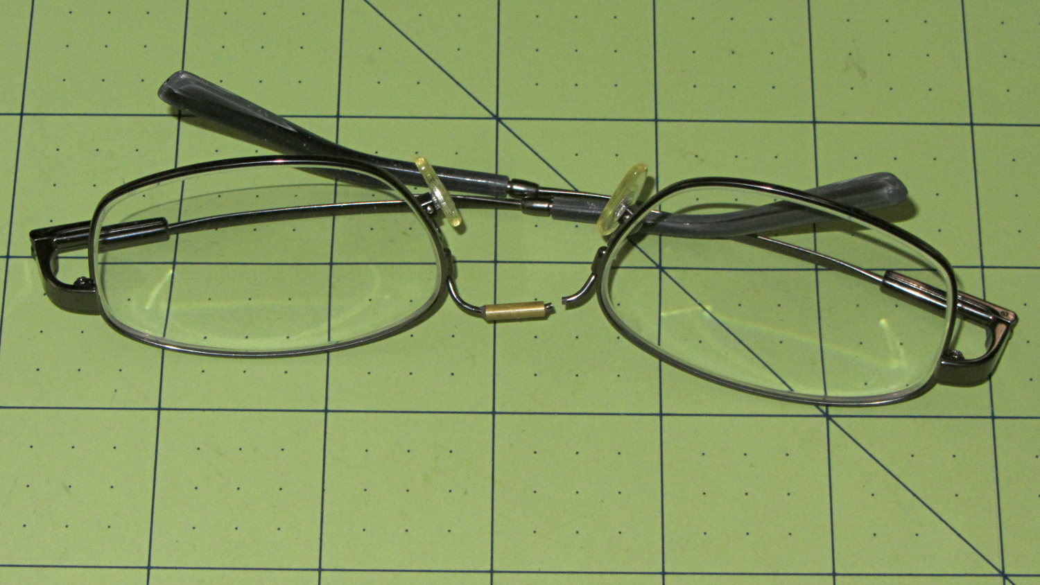
Having repaired these once before, I wasn’t too surprised when this happened:
Eyeglasses – broken nose bridge wire
Evidently the “titanium” has fatigued, because the repair lasted barely nine months.
Rather than try to fix them again, I sent my new prescriptions halfway around the planet and, a bit under two weeks later, had three glasses: normal, computer, and sun. This time, I went with 38 mm tall lenses, a heavier nose bridge, and traditional aviator sunglasses.
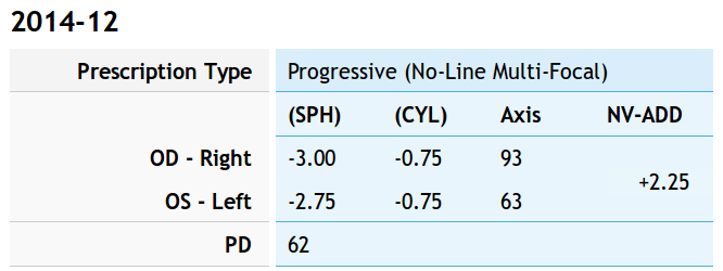
For the record, the regular prescription was:
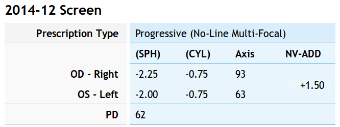
Tweaking that by +0.75 diopter on the sphere puts my far point focus on the monitors across the desk and backing -0.75 diopter from the adder keeps the same near-point reading correction:
Computer prescription – 2014-12
They’re all no-line progressive bifocals made from 1.57 high-index plastic with anti-reflection coating, for a grand total of $135 delivered.
Part of the flailing about while working around the Ubuntu video driver update glitch included blindly swapping a Displayport cable, which triggered another failure after everything settled down: the (empty) DVD drive’s activity light remained dimly lit with the PC off and both monitors in power-save mode. Unplugging the PC’s power cord extinguished all the internal LEDs on the system board, but left the drive light shining the same dim green. Disconnecting the USB cables to the monitors (they both have USB hubs) had no effect. Unplugging the monitors extinguished the LED after a bit. Unplugging one of the Displayport cables turned it off instantly, which was a clue that took a while to recognize.
Worse, the landscape monitor, a year-old Dell U2711, now refused to wake up from power-save mode during boot, even when it was the only monitor connected to the PC. Searching with an assortment of relevant keywords produced severalinterestingresults, including a lengthy Dell support forum thread, all suggesting a deeper and surprisingly longstanding problem with Displayport connections on big Dell monitors.
I knew most of the remedies weren’t relevant, because this failure happened while the BIOS felt around to identify the monitors: not a driver issue (not in effect yet), not a Windows issue (fer shure!), not a Linux issue, and not a BIOS configuration issue (nothing changed, plus Dell doesn’t allow much configuration).
It turns out that the original pair of Displayport cables bore Amphenol logos on the connector shells and cable. One of the replacements was a Genuine eBay cable from halfway around the planet, bearing no markings of any sort. Given the hints in those search hits, I discovered that the Amphenol-branded cables did not carry pin 20 between the connectors, but the eBay cables did: just a little something extra from eBay!
Installing the two Amphenol cables extinguished the DVD drive light by preventing the monitor standby power from backfeeding the PC through the video card and the monitor woke up correctly on the next two boots. Whether that will permanently cure the startup problem remains to be seen, as it was somewhat intermittent with the wrong cable and the forum threads suggest that the monitor will continue to work for a while before failing again.
While pondering all that, I severed the pin 20 connection in one of the eBay cables, just to have a different cable in hand. This diagram from the Wikipedia article, with pin 20 highlighted, shows it sitting under the longer blank section above one of the keys:
DisplayPort Connector – pin 20 highlight
The connector shell has snap latches that succumb to gentle prying with a razor knife, revealing the hot-melt-glue potted interior, with the orange wire snaking away from pin 20 at the top of the other side:
DP connector – latch side
One snip, a bit of prying to extract the end from the glue, and it’s ready to be buttoned up again:
DP connector – pin 20 wire cut
Both Amphenol cables and the modified eBay cable now have labels noting that they do not connect pin 20. We’ll see if that makes any difference…
case PD_RUN :
	if (PedalPosition > 5) {
		if (MotorDrive.State != RUNNING) {
			EnableMotor();
			MotorDrive.State = RUNNING;
		}

		BaseDAC.setVoltage(0x0fff,false);								// give it a solid pulse
		SampleCurrent(PIN_CURRENT_SENSE);								// sample over a half cycle
		if (DriveOnTime > CurrentSamplingTime) {
			delay(DriveOnTime - CurrentSamplingTime);
		}

// Pedal to the metal?
//   ... if so, stall here with motor drive fully on until the pedal releases

		while ((MotorDrive.SpeedRange == SPEED_HIGH) && (PedalPosition >= 100)) {
			PedalPosition = PedalPercent(ReadAI(PIN_PEDAL));
		}

		BaseDAC.setVoltage(0,false);									//  ... then turn it off

		delay(map(constrain(PedalPosition,0,PedalMaxClamp),
				0,100,
				DriveOffTime,0));
	}
	else {
		if (MotorDrive.State == RUNNING) {
			if (MotorSensor.RPM) {
				printf("Coast: %d\r\n",MotorSensor.RPM);
				delay(100);
			}
			else {
				printf("Parking ");
				ParkNeedle(MotorDrive.ParkPosition);
				MotorDrive.State = STOPPED;
				printf(" stopped\r\n");
			}
		}
	}
	break;
The magic happens in highlighted statement, which flips the sense of the pedal motion and linearly scales the result into a delay() value ranging from 120 ms (pedal barely pressed) down to 0 ms (pedal almost fully pressed). If the pedal is all the way down, then the preceding while() locks up until it’s released a bit, whereafter the delay will be nearly zero.
That sorta-kinda worked, but the user community said that the pedal response required pushing too hard for top speed: it should get faster, sooner. The problem came from the simplistic way I set the speed: it was inversely proportional to the position.
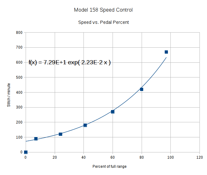
Plotting speed against pedal position shows the problem:
Speed vs pedal – period control
I figured the right approach was to make the speed vary linearly with the pedal position, so the trick was to plot the off-time delay vs. the actual speed:
Off-time delay vs speed – period control
The second-order equation bottles up a bunch of nonlinear things. Given that this was using the original code, I made the dubious assumption that more-or-less the same delay in the new code would produce more-or-less the same speed.
The new code discards the current-sampling routine that I was using to get a fixed delay (because I don’t need to know the current in pulse-drive mode), then used that time for the floating-point calculation required to find the off-time delay. That chunk of code took a bit of fiddling to get right:
case PD_RUN :
	if (PedalPosition > 5) {
		if (MotorDrive.State != RUNNING) {
			EnableMotor();
			MotorDrive.State = RUNNING;
		}

		BaseDAC.setVoltage(0x0fff,false);								// give it a solid pulse
		MillisOn = millis() + (unsigned long)DriveOnTime;

		TargetSpeed = (float)map(constrain(PedalPosition,0,PedalMaxClamp),
				0,100,
				0,700);						// quick and dirty 0 to 700 stitch/min range
		OffTime = (int)((1.94e-4*TargetSpeed - 0.286)*TargetSpeed + 106.0);
		OffTime = constrain(OffTime,0,120);								// clamp to reasonable range
		MillisOff = MillisOn + (unsigned long)OffTime;					// compute end of off time

		while (millis() <= MillisOn) {									// wait for end of pulse
			continue;
		}

		if ((PedalPosition >= 100) && (MotorDrive.SpeedRange == SPEED_HIGH)) {	// pedal down in full speed mode?
			printf("Full speed ... ");
			OffTime = 0;
			while (PedalPosition >= 100) {								//  ... full throttle!
				PedalPosition = PedalPercent(ReadAI(PIN_PEDAL));
			}
			BaseDAC.setVoltage(0,false);								//  pedal released, start coasting
			printf(" done\r\n");
		}
		else {															// pedal partially pressed
			BaseDAC.setVoltage(0,false);								// pulse done, turn motor off
			while (millis() <= MillisOff) {								// wait for end of off period
				continue;
			}
		}
	}
But the result looks as pretty as you could possibly expect:
Speed vs pedal – linearized speed control
The pedal still provides a soft-start transition from not moving to minimum speed, which remains an absolute requirement: having an abrupt transition to that straight line would be a Bad Thing. Fortunately, the nature of the magnet moving toward the Hall effect sensor gives you that for free.
Although we’re still evaluating the results, the user community seems happier…
So there’s been a conflict between Ubuntu’s kernel update procedure (which has trouble with non-GPL kernel modules) and the nVidia proprietary drivers (which you must use in order to Make Things Work). Ever since 14.04LTS came out, some-but-not-all kernel updates have produced anything from no problem at all to a totally broken system requiring esoteric manual tweakage that shouldn’t be expected of mere mortals.
**WARNING:** This bug has been widely reported and has *many* automatic subscribers. Please be considerate.
The most recent update to my desktop box clobbered it hard enough that the landscape display didn’t start up properly and the portrait display wasn’t rotated. The same update to other boxes seems to have worked, but that may be a set of unwarranted assumptions; the boxes simply haven’t displayed any obvious symptoms.
After having to fix this mess every now and again over the last year, this worked:
sudo apt-get install --reinstall nvidia-331-uvm
As nearly as I can tell, reinstalling any nVidia package that’s already installed simply retriggers the failing step, resulting in a clean and workable installation. There’s apparently something wrong with the Dynamic Kernel Module Support structure that works the second time around, but I have no idea (and little interest) about the details.
However, that “fix” required this sequence:
Boot the rescue session from the Grub menu
Activate networking
Clean out any broken packages
Drop to a root shell prompt
Do the apt-get dance
Power off
Unplug the portrait montitor’s Displayport cable
Boot to the BIOS settings to force-start the landscape monitor
Power off
Reconnect the portrait monitor
Reboot into Xubuntu as usual
Reset the monitor positions
Reload the desktop backgrounds
Now, at least, all that’s written down where I can refer to it the next time this happens… on a separate laptop, of course.
This has been happening for nigh onto a year in what Ubuntu charmingly calls a “long term support” release.
Adjusting the output voltage vs. position for the sewing machine’s food pedal quickly revealed that the code shouldn’t depend on the actual ADC values. That’s blindingly obvious in hindsight, of course.
The maximum with the pedal in its overtravel region doesn’t change by much, because the Hall effect sensor output voltage saturates in a high magnetic field. I used a hardcoded word PedalMax = 870; which comes from 4.25 V at the ADC input.
On the low end, the sensor output can change by a few counts depending on small position changes, so I sampled the (presumably released) pedal output during the power-on reset:
	PedalMin = ReadAI(PIN_PEDAL);				// set minimum pedal input value
	printf("Set PedalMin: %u\r\n",PedalMin);
	PedalMaxClamp = 100;						// set upper speed limit
Given the complete ADC range, this function normalizes a value to the range [0,100], conveniently converting the pedal position into a percent of full scale:
int PedalPercent(word RawPos) {
int Clamped;

	Clamped = constrain(RawPos,PedalMin,PedalMax);
	return map(Clamped,PedalMin,PedalMax,0,100);
}
Graphing the normalized values against pedal position would have the same shape as the ADC values. All I’m doing is rescaling the Y axis to match the actual input limits.
The top of the main loop captures the pedal position:
Now, it’s easy to add a slight deadband that ensures the sewing machine doesn’t start when you give the pedal a harsh look; the deadband is now a percent of full travel, rather than a hard-coded ADC count or voltage.
For example, in needle-follows-pedal mode, you must press the pedal by more than 10% to start the stitch, slightly release it to finish the stitch, and then almost completely release it to proceed to the next stitch:
	case PD_FOLLOW:
		if (PedalPosition > 10) {
			printf("Pedal Follow\r\n");
			ParkNeedle(NS_DOWN);
			do {
				PedalPosition = PedalPercent(ReadAI(PIN_PEDAL));
			} while (PedalPosition > 10);
			ParkNeedle(NS_UP);
			do {
				PedalPosition = PedalPercent(ReadAI(PIN_PEDAL));
			} while (PedalPosition > 2);
		}
		break;
Adjusting percentages turns out to be much easier than fiddling with ADC values.