Ed Nisley's Blog: Shop notes, electronics, firmware, machinery, 3D printing, laser cuttery, and curiosities. Contents: 100% human thinking, 0% AI slop.
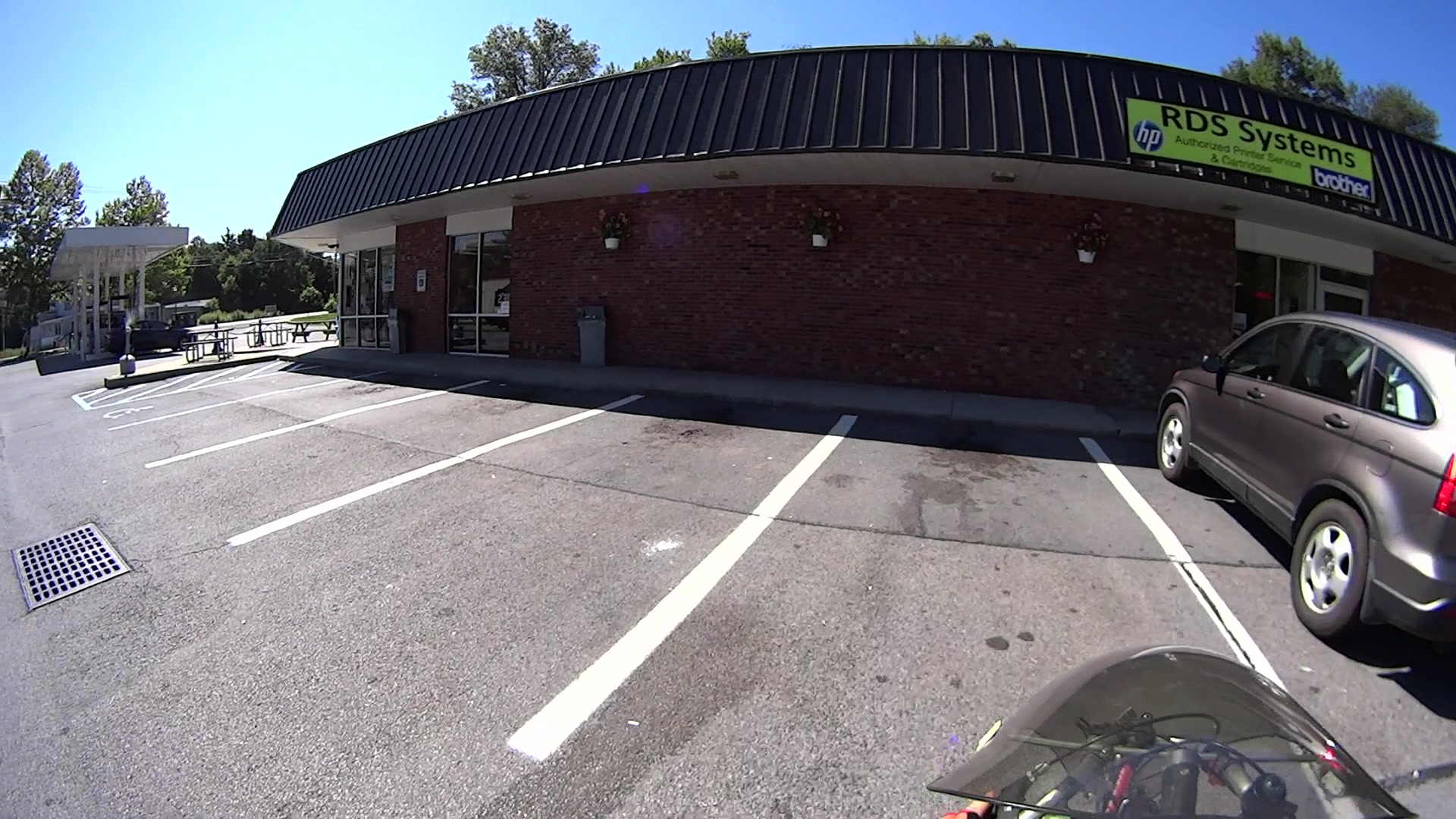
My Sony HDR-AS30V is an action camera, but requires an external case / frame to mount it on anything. Here’s the camera inside its AKA-SF1 Skeleton Frame atop my helmet:
Sony HDR-AS30V camera on bike helmet – inverted
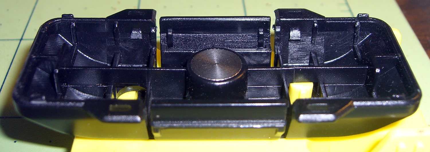
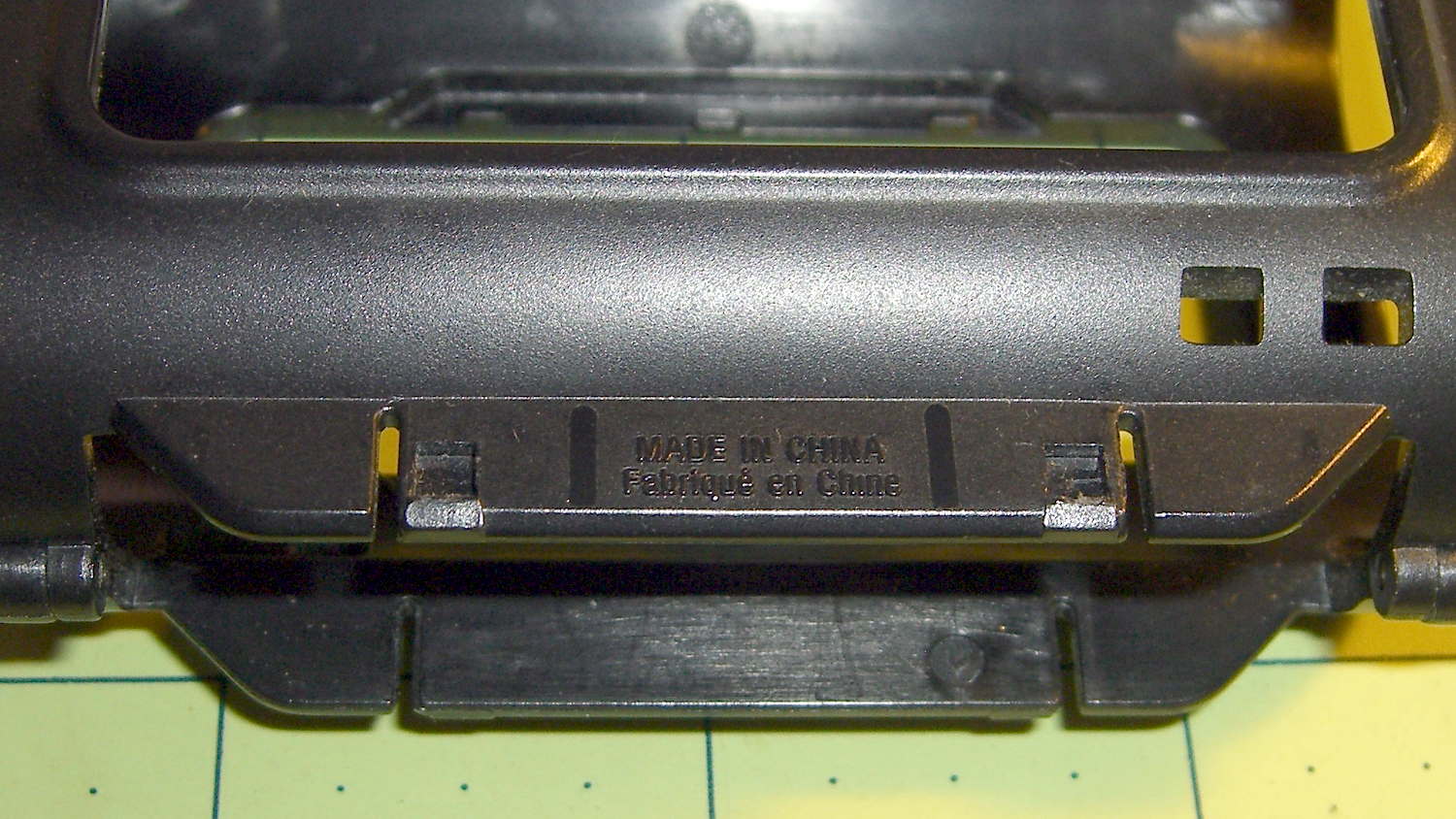
Four 1 mm tall ramps on the inside of the black base (the part just above the yellow sled) snap into 2.6 mm square sockets in the skeleton frame surrounding the camera. For an unknown reason(s) that surely involves applying forces I don’t remember, an opposing pair of those ramps broke off, leaving the other pair to loosely hold one end of the camera in place.
In this picture, the left ramps (one visible) are missing, leaving a square-ish gray scar that’s nearly indistinguishable from the reflection on the intact ramp on the right:
Sony HDR-AS30V Skeleton Mount – broken latch ramps
Surprisingly, the round head of a brass 0-80 machine screw fits neatly inside the square socket on the frame; they’re a bit more than 1 mm deep. The approach ramps visible below the sockets guide the latches on the base:
Sony HDR-AS30V Skeleton Mount – frame sockets
So I figured I could just shave off the remaining two latch ramps, drill four holes at the proper spots, and replace the plastic ramps with metal screws.
I clamped the skeleton frame to the Sherline’s tooling plate, aligned it parallel to the X axis, put the laser spot dead center in the square socket, then snapped the base onto the frame. The laser spot shows where the drill will hit:
Sony HDR-AS30V Skeleton Mount – laser hole alignment
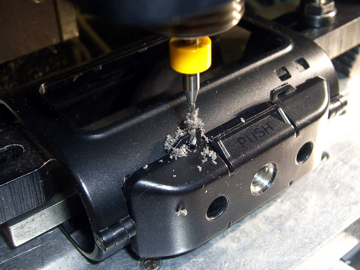
A carbide drill did the honors:
Sony HDR-AS30V Skeleton Mount – 0-80 hole drilling
That’s a #55 = 0.0520 hole for 50% thread, rather than the proper 3/64 = 0.0469 hole for 75% thread, because that’s the closest short carbide drill I had; an ordinary steel twist drill, even in the screw-machine length I use on the Sherline, would probably scamper away. The hole isn’t quite on the sloped bottom edge of the base, but it’s pretty close.
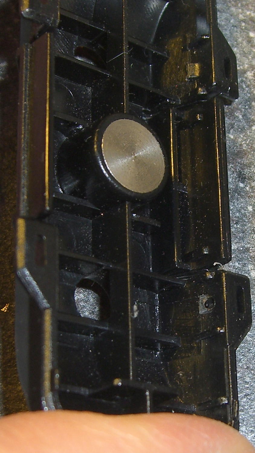
The first hole didn’t emerge quite in the center of its ramp scar:
Sony HDR-AS30V Skeleton Mount – hole position – interior
Which made sense after I thought about it: the ramp tapers to nothing in the direction of the offset, so the hole actually was in the middle of the matching socket.
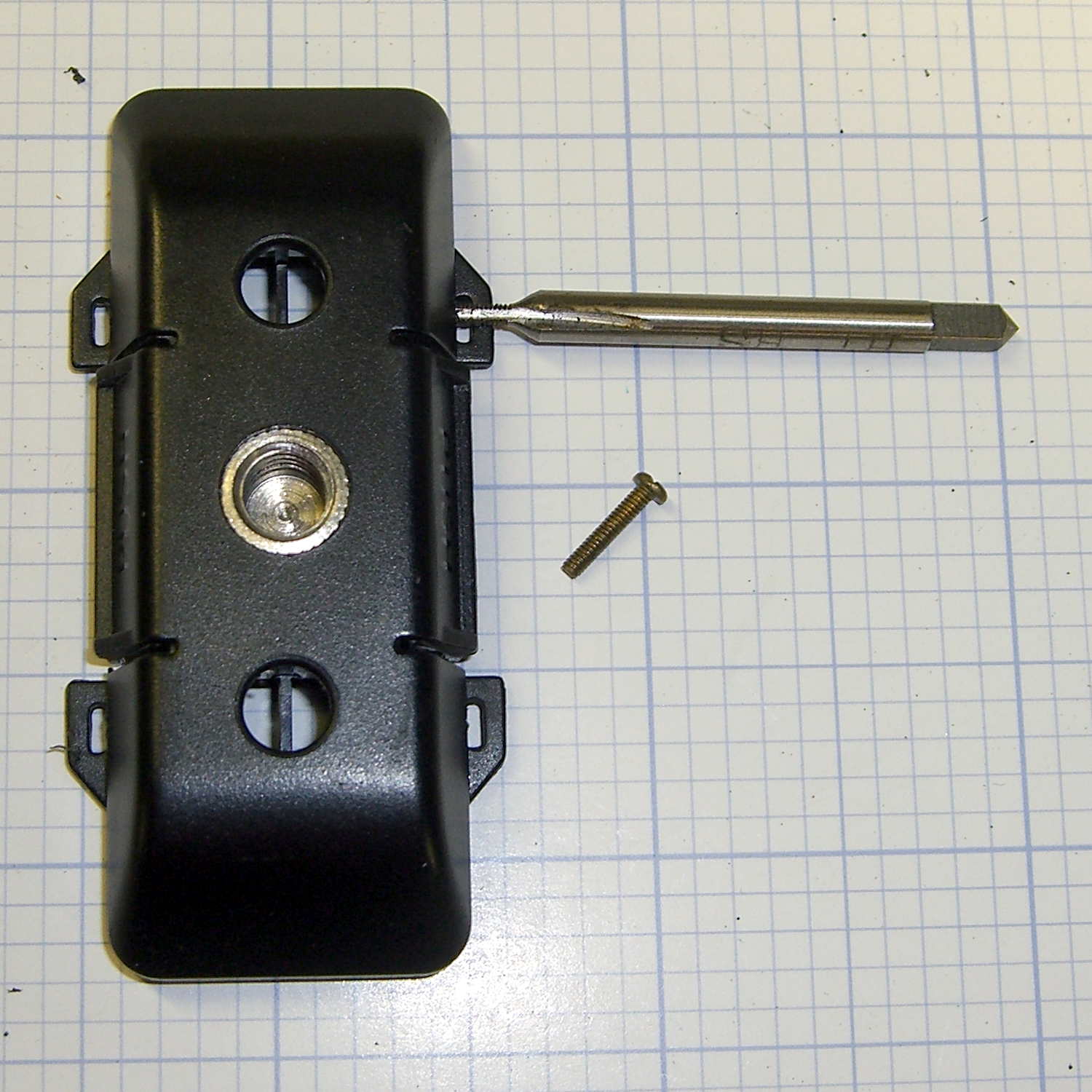
Threading the holes required nothing more than finger-spinning an 0-80 tap:
Sony HDR-AS30V Skeleton Mount – tapping 0-80
The feeble thread engagement didn’t matter, because those mysterious tabs-with-slots (possibly for tie-down strings?) just above the holes were a perfect fit for 0-80 brass nuts:
Sony HDR-AS30V Skeleton Mount – reassembled
The screw heads extend into the sockets, hold the frame solidly in the base, and make it impossible to pull out. Although the frame still slides / snaps into the base, that seems like it will wear out the sockets in fairly short order, so I’ll unlatch the frame (with the yellow slide latch on top), open it up, ease it into position, and then latch it in place. That was the only way to remove it from the original latches, so it’s not a big deal.
I should add a drop of epoxy to each of those nuts and perhaps fill the screw slots with epoxy to keep them from abrading the plastic inside the sockets. Maybe a dab of epoxy on the heads, followed by latching the frame in place, would form four square pegs to exactly fill the sockets.
This was a straightforward repair that should not have been necessary…
Compiling it from source required installing two dependencies, which I discovered by the simple expedient of iteratively smashing into “fatal error: parted/parted.h: No such file or directory” messages:
libudev-dev
libparted0-dev
With those in place, unleashing f3probe on the most recent replacement Sony 64 GB MicroSD card went swimmingly:
sudo ./f3probe --time-ops /dev/sdb
F3 probe 5.0
Copyright (C) 2010 Digirati Internet LTDA.
This is free software; see the source for copying conditions.
Please unplug and plug back the USB drive. Waiting... Thanks
Please unplug and plug back the USB drive. Waiting... Thanks
Please unplug and plug back the USB drive. Waiting... Thanks
Please unplug and plug back the USB drive. Waiting... Thanks
Please unplug and plug back the USB drive. Waiting... Thanks
Please unplug and plug back the USB drive. Waiting... Thanks
CAUTION		CAUTION		CAUTION
No more resets are needed, so do not unplug the drive
Probe finished, recovering blocks... Done

Good news: The device `/dev/sdb' is the real thing

Device geometry:
	        *Real* size: 60.37 GB (126613504 blocks)
	     Announced size: 60.37 GB (126613504 blocks)
	             Module: 64.00 GB (2^36 Bytes)
	Physical block size: 512.00 Byte (2^9 Bytes)

Probe time: 61.19 seconds
Probe read op: count=775, total time=4.00s, avg op time=5.16ms
Probe write op: count=753, total time=3.77s, avg op time=5.00ms
Probe reset op: count=6, total time=53.42s, avg op time=8903.21ms
As predicted, most of the time passed while I fiddled with the SD Card adapter in the slot on the side of the U2711 monitor: push to release, push to insert, repeat as prompted.
Despite the f3fix program’s ability to “repair” counterfeit USB memory by resetting the partition to the actual capacity, I think that’s a Bad Idea. Based on my admittedly limited experience, counterfeit junk generally doesn’t come from the middle of the quality-control bell curve, so expecting that crap to actually work over the long term seems, shall we say, overconfident.
The f3 doc also told me about lsblk, which may come in handy every now & again:
lsblk
NAME   MAJ:MIN RM   SIZE RO TYPE MOUNTPOINT
sda      8:0    0 111.8G  0 disk
├─sda1   8:1    0  56.8G  0 part /
└─sda2   8:2    0   9.3G  0 part [SWAP]
sdb      8:16   1  60.4G  0 disk
└─sdb1   8:17   1  60.4G  0 part /media/ed/9C33-6BBD
sr0     11:0    1  1024M  0 rom
Now I have a reminder of how to do this for The Next Time…
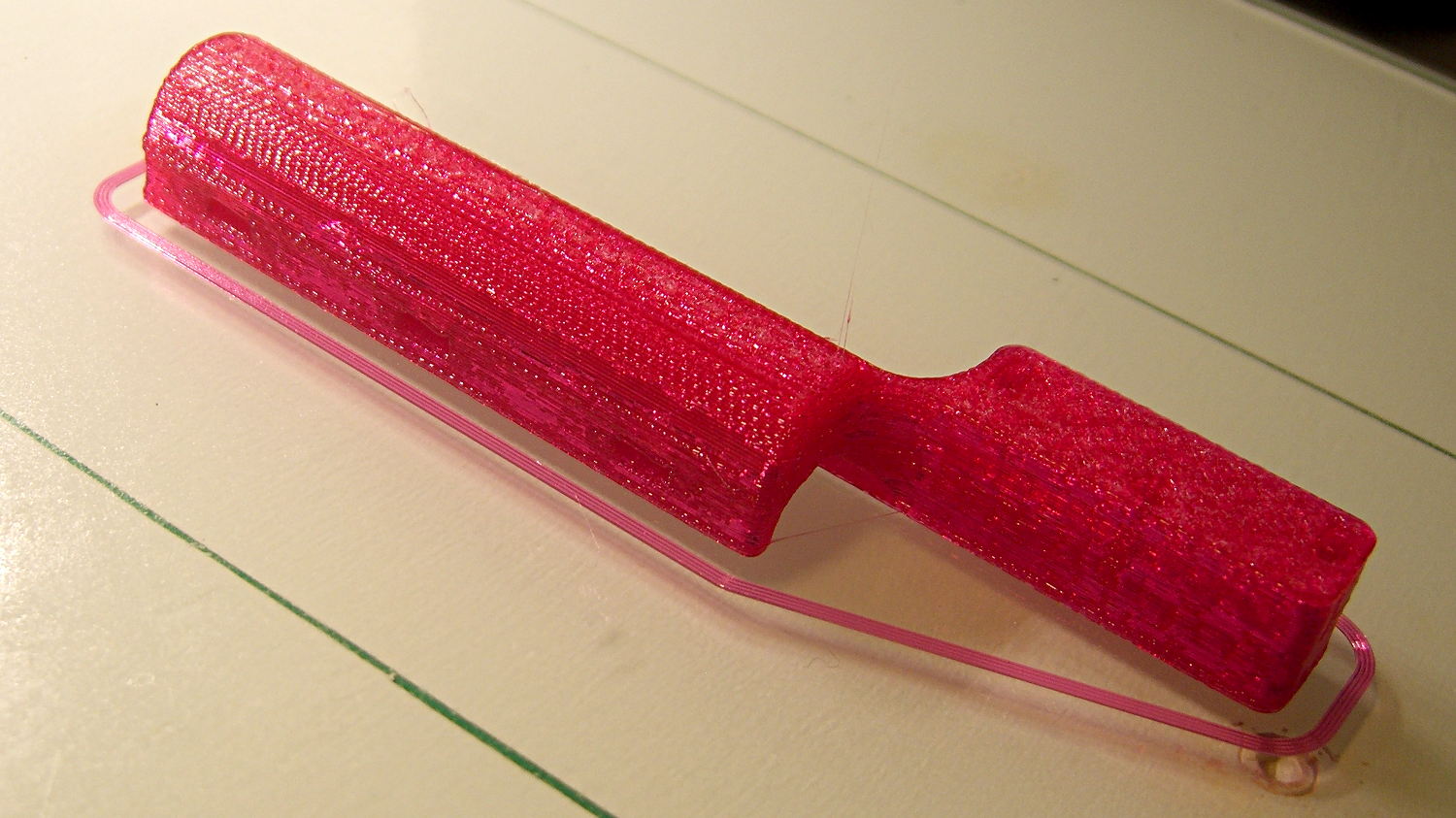
The elevation tension adjustment on both our bike helmet mirror mounts have become a bit sloppy. That’s no surprise, because I expected the tiny set screw in the tiny square hole near the top to eventually wear a depression in the ABS plastic arc upon which it bears:
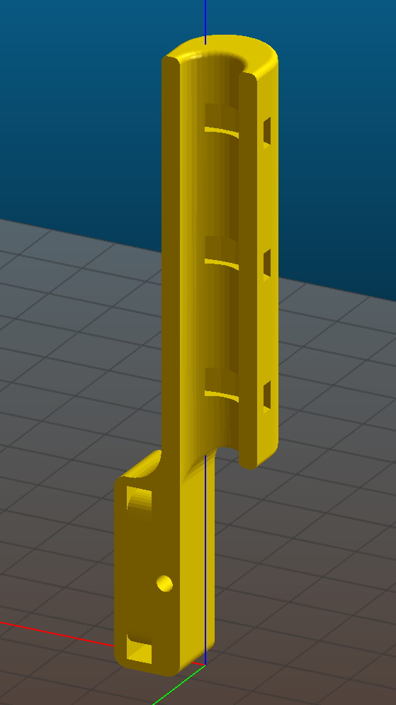
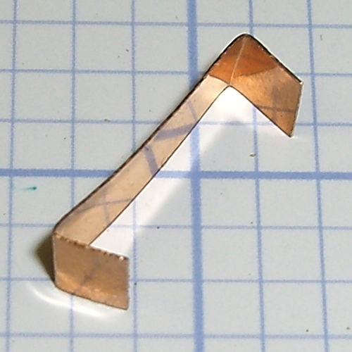
So I got to do something I planned pretty much from the beginning of the project: cut a snippet of phosphor bronze spring stock to go between the Elevation mount and the arc, then bend the ends bent inward so they don’t slash an errant fingertip:
Helmet mirror mount – elevation slide
Slipped in place, the ends look like they stick out anyway, but they’re really just about flush:
Helmet mirror mount – El slide in place
Tightening the set screw pushes the strip against the arc, where it provides enough resistance to prevent slipping and enough smoothness for easy adjustment.
While I had the mounts up on the repair stand, I unscrewed the mirror shaft and snugged up the Azimuth pivot screw by a micro-smidgen to tighten that motion.
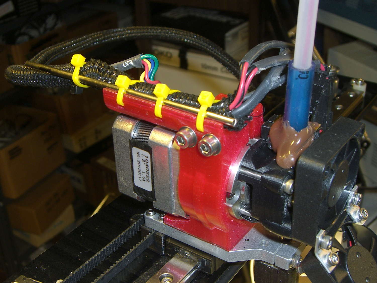
Four years ago, those ABS parts popped off the much-hacked Thing-O-Matic’s platform. The M2 produces somewhat better-looking results, but that yellow plastic has a certain charm…
Plotters date back to the days before companies started using DRM to protect their monopoly positions, so refilling plotter pens requires little more than prying out the plug and squirting in more ink. Refilling the disposable liquid ink pens and the green ceramic pen suggested this would work.
I shaved down the side of a Genuine HP pen to find out why the plug didn’t pop out. It turns out the plug has a long and aggressively ribbed profile to ensure a gas-tight fit:
HP Plotter Pen – exposed plug
The easiest way to refill those is to drill an off-center 1/16 inch hole in the plug, then inject ink into the sponge with a syringe and blunt needle (and bulk ink!) from an inkjet cartridge refill kit. Angling the needle through the sponge close to the pen wall, then filling slowly, loads the sponge from the bottom up and expels the air along the way.
Inmac pens have a shallow plug, more of a flat cap, that pries out with zero drama:
Inmac Plotter Pen – removed plug
Dripping the ink atop the sponge seems to work well, although that sponge is definitely over-filled.
Inmac caps push back in place with zero drama.
The pens have fiber nibs with vent channels along their sides that allow air into the reservoir, so overfilling the sponge nets you a mess when you take the cap off the nib: those same channels allow excess ink to run from the reservoir around the nib, without (much to my surprise) wetting the fiber tip.
About 0.2 ml of ink fills the reservoir to saturation, 0.1 ml leaves it wet, and 0.05 ml seems to work well. The 1.0 ml syringes I’m using require about 0.05 ml to fill the (blunt!) needle shaft & hub, plus the syringe tip below the 0.0 ml index, so measuring the ink by drops might make practical sense.
The old physician’s trick of expelling that air by inverting the syringe and pressing the plunger until liquid squirts from the needle is so not happening…
I’ve had zero success refilling fossilized pens, probably because the OEM ink slowly evaporating from the nib clogs all the gaps between the fibers with pigment or coagulated solvent. Preemptively refilling good pens when they first show signs of running dry generally works well.
Given the number of New Old Stock pens I have that are still in their original wrappers, this is more of a “Does it work?” exercise than a necessity.
But, y’know, maybe becoming the last plotter pen refiller on the planet will be my ticket to fame & fortune! For sure, we’ve all seen over-hyped Internet startups with worse business plans and (the admittedly few) typewriter repair shops occupy a stable niche.
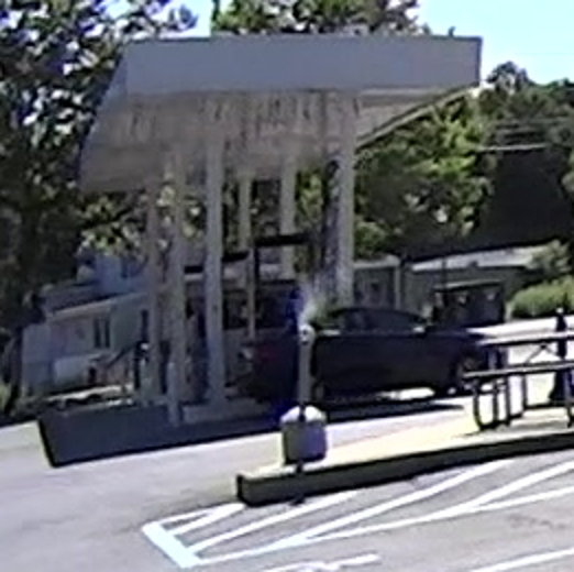
As I rolled into the Stewart’s Shop on a milk-and-eggs run, a plume of smoke spiraled out of the cigarette butt station near the door, way off on the left side:
Smoldering Cigarette Dump
A closer look:
Smoldering Cigarette Dump – Detail
By the time I unhitched myself from the bike and reached the door, two smoke jets squirted from the top and a pall of breathtakingly foul smoke filled the parking lot. I mooched a big cup of water from the folks behind the counter and pulled off the container’s lid, which let in enough oxygen to ignite a full-up fire in the heap of cigarette packs, plastic wrappers, butts, lottery tickets, receipts, and other combustible junk atop the sand bucket in the base of the butt dump. Sprinkling the water over the blaze knocked it back; I replaced the lid and declared victory.
I always take a shower after returning home from a ride, but, this time, we also ran all my bike clothing through the washer right away.
Phew…
Verily, it is written: Kissing a smoker is like licking an ashtray.