Ed Nisley's Blog: Shop notes, electronics, firmware, machinery, 3D printing, laser cuttery, and curiosities. Contents: 100% human thinking, 0% AI slop.
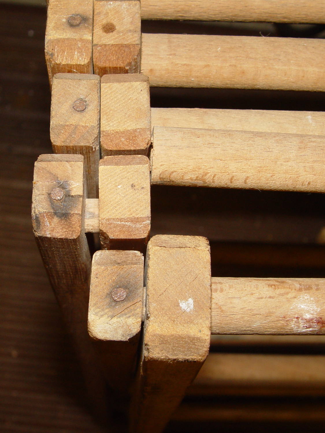
One of the rungs in the drying rack that keeps my bath towel from crawling away broke:
Drying Rack – broken rung
The rungs have turned-down pegs on the ends that slide through the inner side strut and anchor into the outer strut with a nail through the end. You can see the peg between the struts.
Removing the nail split the end of the strut, so I slobbered urethane glue into the crack and clamped it together overnight:
Drying Rack – strut gluing
Rather than removing the strut and doing it right, I gingerly freehanded a 3/8 inch hole into the end with a Forstner bit:
Drying Rack – drilled reinforced rung
Yes, that’s off-center, but it’s dead on the scar where the peg broke off. I have no idea how they could turn down a cylinder to get an eccentric peg on the end.
The black heatstink tubing reinforces the absurdly thin wood shell remaining around the hole. It’s probably not required, given that I’m about to fill the hole with a hardwood peg; nothing exceeds like excess.
Cut a suitable length from a nearby foam paint brush handle that just happens to be both hardwood and 3/8 inch in diameter, dab urethane glue in the holes (but not in the inner strut!), stuff peg through inner strut, seat in outer strut, stretch things enough to slide peg into rung, separate struts to avoid inadvertently pasting them together:
Drying Rack – reassembled
Took about fifteen minutes over the course of three days while the glue cured.
Done!
Those of long memory may recall a similar repair to the previous rack; we do, occasionally, toss things. I did, of course, add some of its dowels to the Long Things Stockpile.
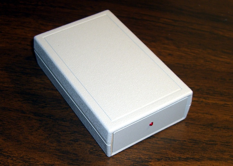
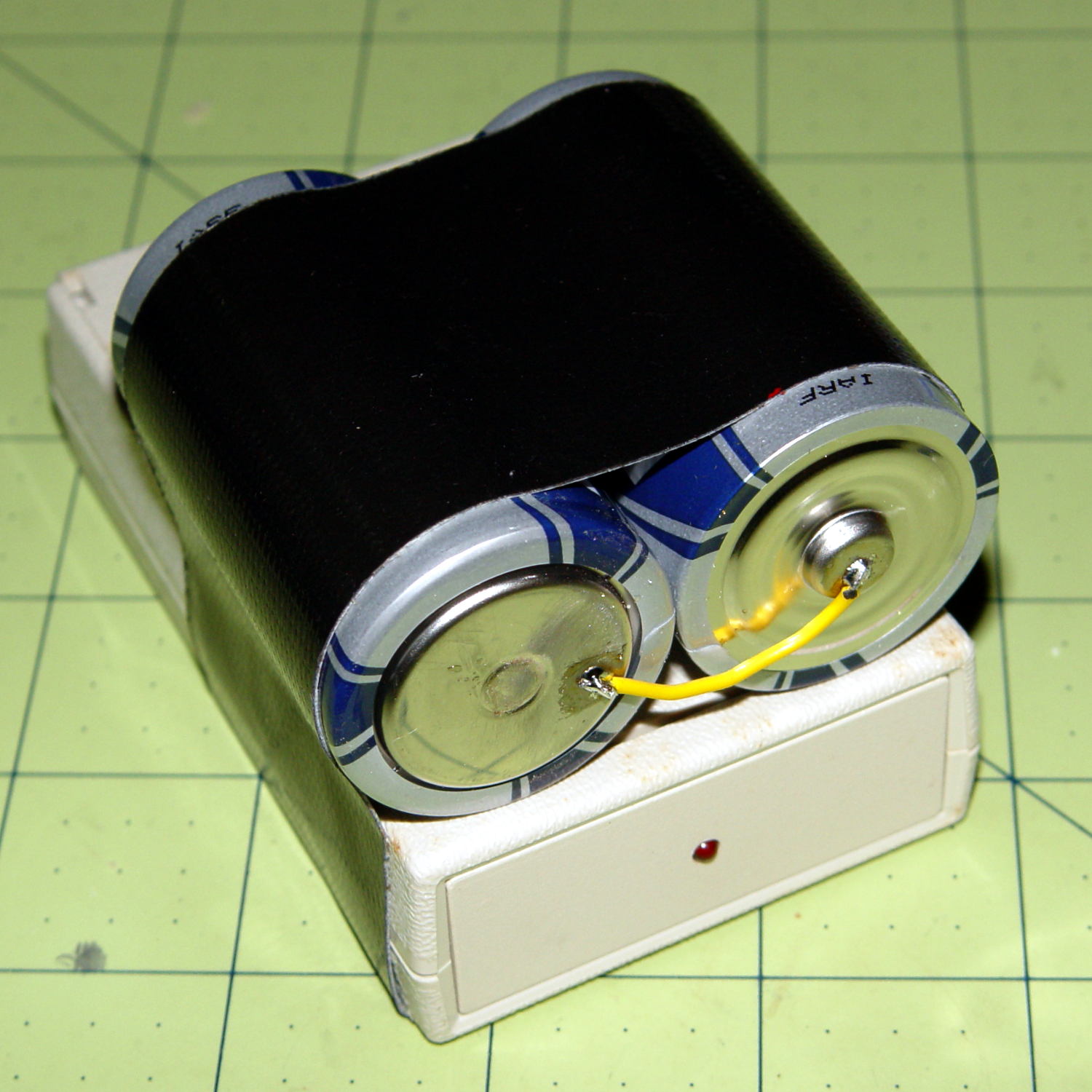
I duct-taped a pair of D cells onto the case and returned it to the bedroom shelf. According to the date scrawled on the tape, that was five years ago: 26 November 2010.
Over the last few months, the LED gradually faded from a blink to a steady glow as the battery voltage dropped below 2 V and the WWVB receiver output no longer reached the MOSFET’s threshold.
We’ll see how long these last:
Alpha Geek Clock – new batteries
Yeah, I should probably do something involving 3D printing…
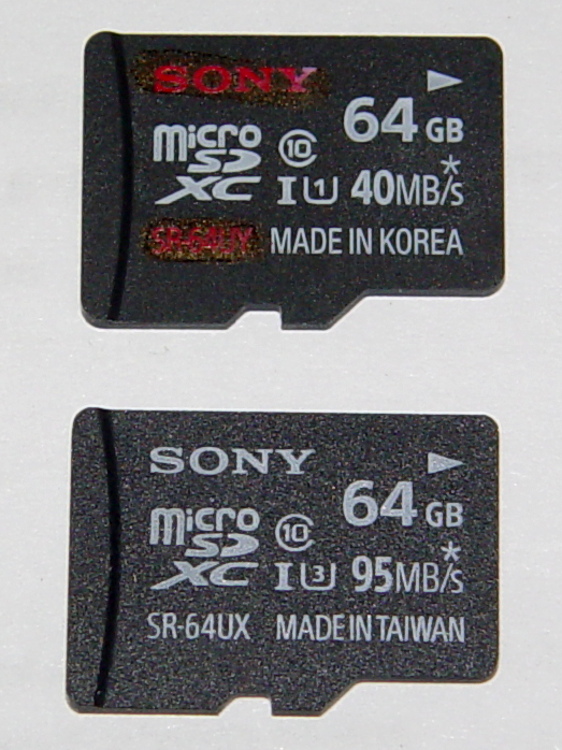
A little over a year ago, I bought two Sony 64 GB MicroSDXC cards (let’s call them A and B). Both cards failed after less than six months in service and were replaced under warranty with Cards C and D:
Sony 64 GB MicroSDXC cards – front
The top card (C) is the most recent failure, the bottom (D) is the as-yet-unused replacement for Card D. Note that the difference: SR-64UY vs. SR-64UX, the latter sporting a U3 speed rating.
Note that the failure involves the card’s recording speed, not its read-write ability or overall capacity. Card C still has its nominal 64 GB capacity and will store-and-replay data just fine, but it can’t write data at the 25 Mb/s rate required by the camera… which is barely a third of the card’s speed rating. Also note that the writing speed is always a minute fraction of the reading speed that you see on the card.
I use these in a Sony HDR-AS30V action camera on my bike, so it’s pure Sony all the way. Although I don’t keep track of every trip, I do have a pretty good idea of what happened…
In service: about 2015-07-10
Failed to record 1920×1080 @ 60 f/s video: 2015-09-22
In round numbers, that’s 70 days of regular use.
My NAS drive has room for about a month of video, depriving me of a complete record of how much data it absorbed, but from 2015-08-21 through 2015-09-22 there’s 425 GB from 25 trips in 30 days. Figuring the same intensity during the complete 70 days, it’s recorded 800 to 900 GB of data (including my verification test). With 60 GB available after formatting, that amounts to filling the card 14 times.
That’s reasonably close to the 1 TB of data I’d been estimating for the failures of Cards A and B, so these Sony cards reliably fail their speed rating after recording 750 GB, more or less, of data.
The simplest possible electrometer amplifier that might work:
Electrometer amp – LMC6081 schematic
The general idea is that the op amp will drive the (essentially) open-circuited inverting input to match the 2 V offset at the noninverting terminal, so that the output will stabilize above the LMC6081’s minimum useful output voltage (of about 1 V) and the gamma-ray pulses will go downward from there (it’s an inverting amp). The rebiasing network downstream from the output cap doesn’t appear in the hardware.
The small cap across the feedback resistor that would compensate / roll off the high-frequency response isn’t possible, unless you have a stockpile of teeny glass vacuum capacitors: the leakage resistance must be far more than 100 GΩ and my collection lacks anything like that. A Teflon-insulated gimmick capacitor wouldn’t be stable enough and would probably still leak crazy current.
Normal electrometer amps operate at essentially DC and amplify an actual current from the ionization chamber. In this case, the radiation level is zero, there’s no chamber current, I’m looking for small pulses generated by gamma ray events, and the amplifier must have reasonable AC response. It’s not clear that circuit can work, but it’s a starting point.
It turned into a hairball:
Electrometer Amp – 10 Gohm Rf
The LMC6081IN is socketed, with the inverting input pin bent outward and soldered to the flying junction of the 100 kΩ input / OMG resistor (which prevents inadvertent shorts from the 24 V chamber bias) and the glass-body feedback resistor. The socket sits end-on in a puddle of epoxy, so I can swap op amps as needed.
The 100 GΩ feedback resistor didn’t work well at all:
LMC6081 100 G – out – noninv level – matched
The lower trace shows the 10.2 VDC offset at the noninverting input, which is what it took to drive the output from near 0 V to the 11.4 V in the upper trace, with no proportional change in between. I replaced the schematic’s 1 MΩ / 220 kΩ resistors with the 20 turn trimpot shown in the photo in order to find that bias condition. Obviously, the op amp acts as an open-loop comparator, not a linear amplifier, and no amount of waiting for it to stabilize would change that outcome.
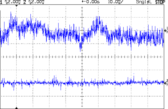
It’s possible the resistor has failed open, but, frankly, the difference between “100 GΩ” and “open circuit” probably doesn’t amount to much. Note, however, that there’s absolutely no 60 / 120 Hz interference or noise, which continues to surprise me; removing the shield cap and teasing the twiddlepot slams the output with a 60 Hz trapezoid:
LMC6081 100 G – out – noninv level
Swapping in a 10 GΩ resistor produced a smoothly changing output for biases between about 1 V and 8 V, so it’s behaving like an op amp should. Setting the non-inverting terminal to 8 V puts the output voltage at 6.3 V, which means the 10 GΩ resistor drops about 1.7 V to pull 170 pA from the inverting input (which is presumably at 8 V give-or-take a bit) and the chamber electrode. The LMC6081 spec says a maximum of 4 pA (for the I version, which is what I have), so:
My cleanliness isn’t up to par
The chamber delivers quite a bit more zero-radiation current than I expected
The op amp’s input got toasted despite my efforts toward a static-free installation
Hard to choose among those options, it is, indeed.
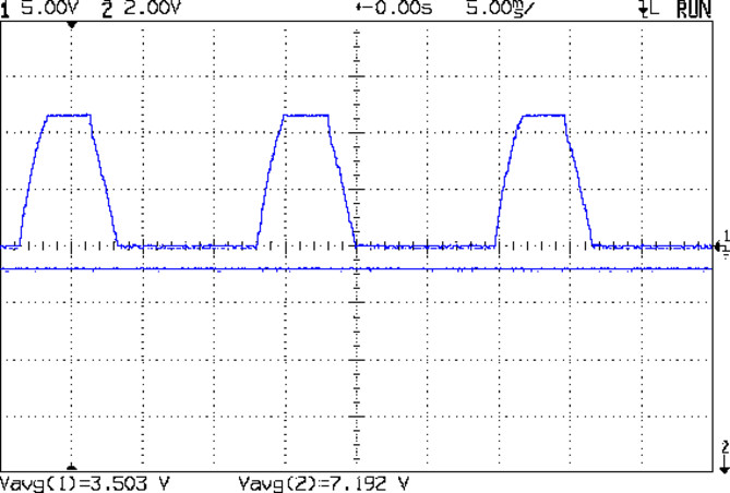
With the bias set to produce a 6 VDC output, the AC coupled signal doesn’t seem promising:
LMC6081 10 G Rf – out and Vplus in – AC 2 mV div
The lower trace is the bias voltage applied to the noninverting input, which looks reasonably clean. The sweep triggers from the power line; there’s still no 60 Hz interference.
All those flying components are, as you’d expect, microphonic beyond belief: jumping on the concrete basement floor produces a corresponding bounce in the trace that may be due to air currents or noise, for all I can tell. Even with the chamber sitting on a loose cloth pad, tapping the workbench produces 10 s of slowly decaying oscillation, admittedly at a much lower frequency than the noise in that trace.
A single gamma ray event producing an unreasonably high 10 fA chamber current will cause a downward (it’s an inverting amplifier) pulse that amounts to a mere 100 µV, a pulse that obviously isn’t visible against all that racket. You might convince yourself that the event at the center of the top trace comes from a gamma ray, but you’d probably be wrong.
In a normal electrometer amp, a stiff low-pass filter discards all the noise and isolates the DC signal corresponding to the steady-state chamber current from the ionizing radiation. Given that the pulses are on the order of 5 ms wide, there’s no obvious way to discard most of the noise without also tossing the signal.
Pending more thought, I’d say this was definitely fun while it lasted…
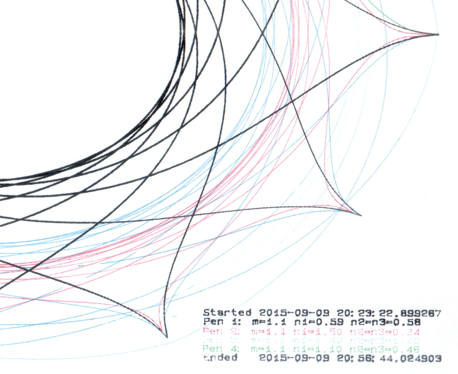
The big bag o’ new-old-stock Inmac ball-point plotter pens had five different colors, so I popped a black ceramic tip pen in Slot 0 and ran off Yet Another Superformula Demo Plot:
HP 7475A – Inmac ball pens – weak blue
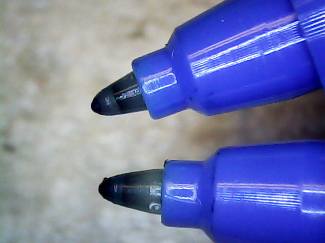
All the ball pens produce spidery lines, but the blue pen seemed intermittent. Another blue pen from the bag behaved the same way, so I pulled the tip outward and tucked a wrap of fine copper wire underneath. You can see the wire peeking out at about 5 o’clock, with the end at 3-ish:
HP 7475A – Inmac ball pen – wire spacer
The wire holds the tip slightly further away from the locating flange and, presumably, makes it press slightly harder against the paper:
HP 7475A – Inmac ball pen – stock vs. extended
A bit more pressure helped, but not enough to make it dependable, particularly during startup on the legend characters:
HP 7475A – Inmac ball pens – extended blue
That black line comes from an ordinary fiber-tip pen that looks like a crayon on a paper towel by comparison with the hair-fine ball point lines.
Delicacy doesn’t count for much in these plots, so I’ll save the ball pens for special occasions. If, that is, I can think of any…