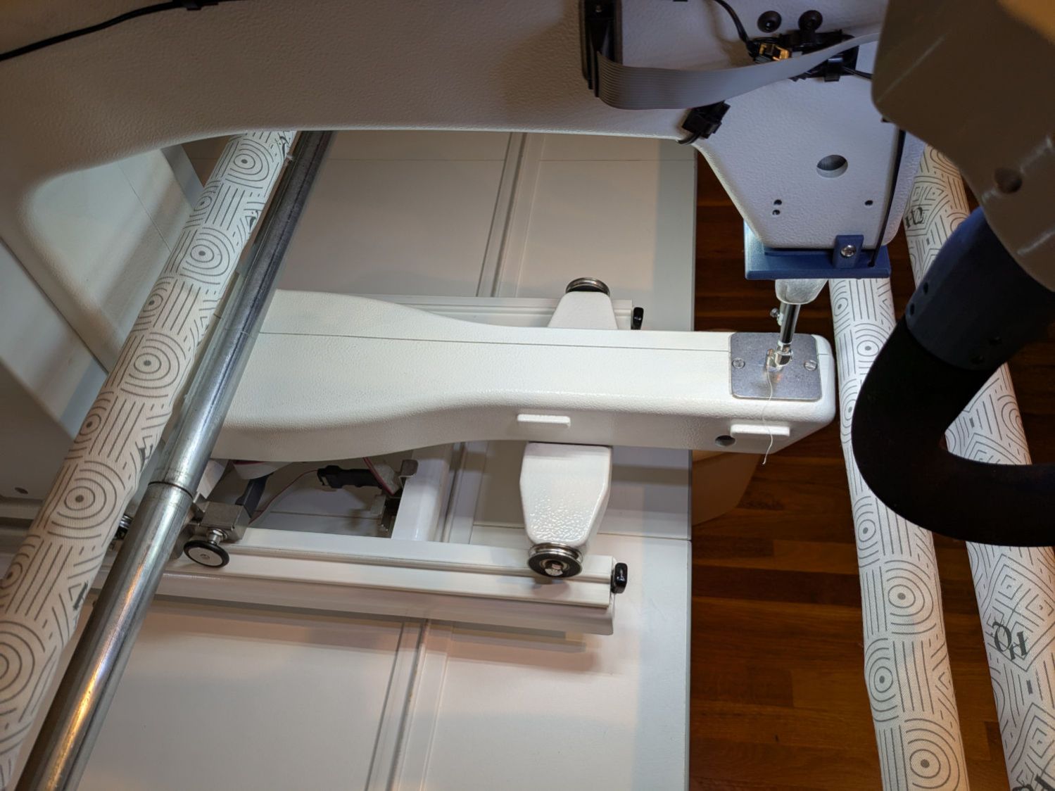
The upstairs Sewing Room came with a couch-like bed incorporating a roll-out trundle bed. It doesn’t get a lot of use, but it lacks wheel locks and tends to scoot away unless you get into it rather more carefully than seems reasonable.
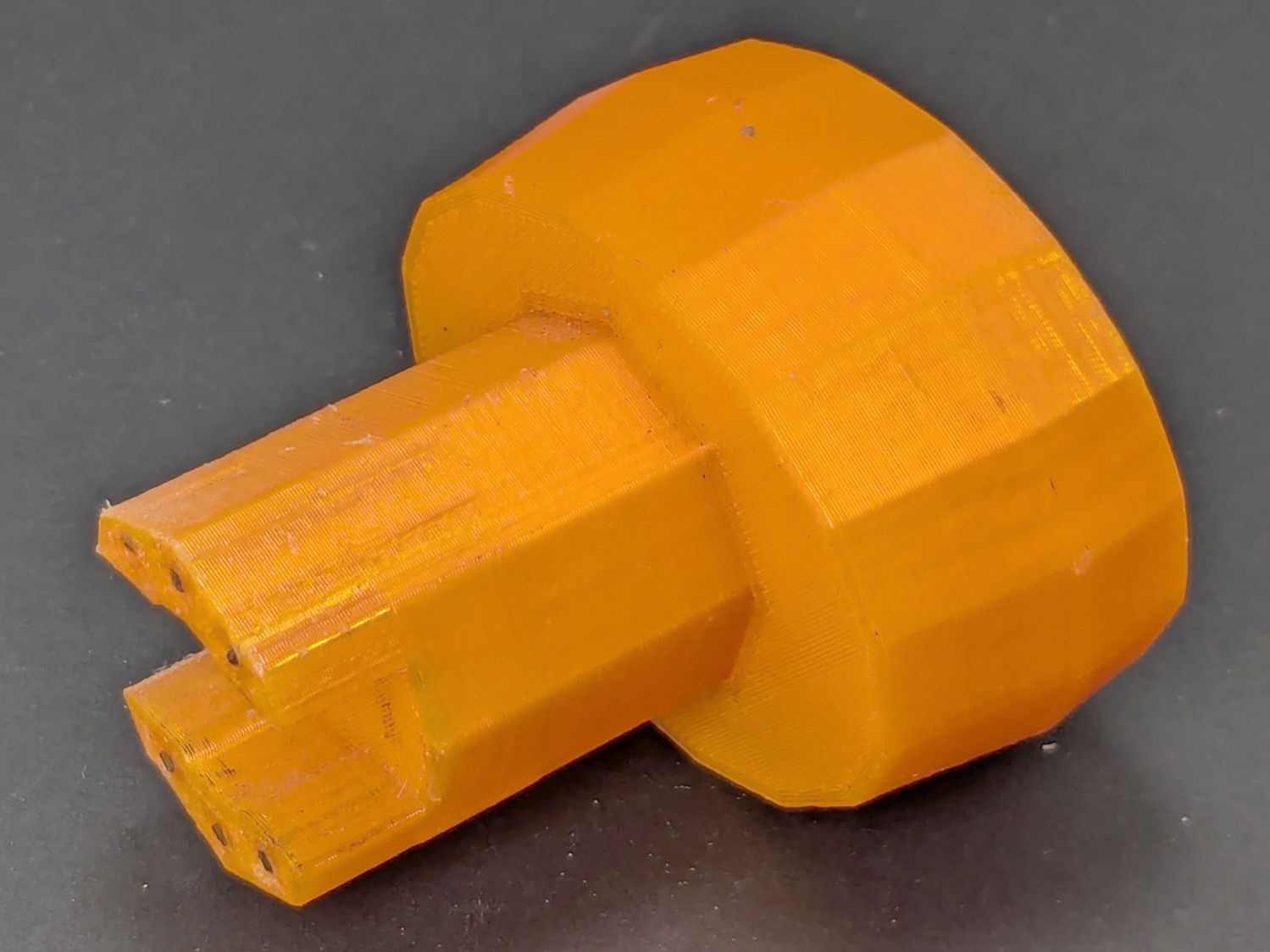
So I made a pair of stops to capture the wheels:
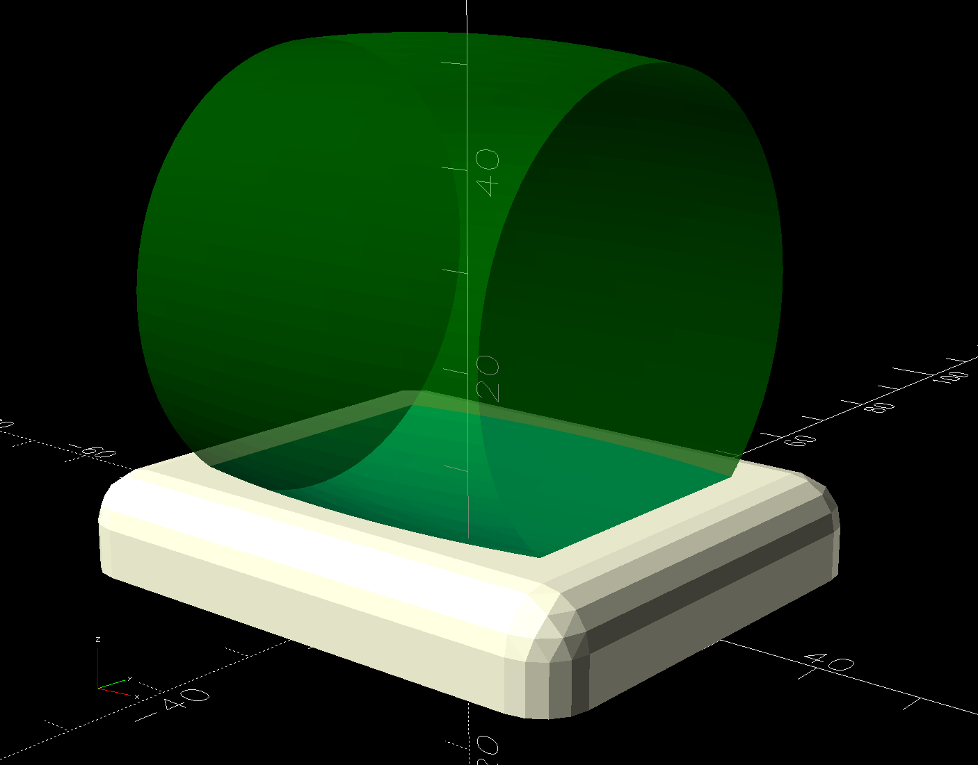
The solid model shows they’re just plastic blocks minus a model of the roller wheel:
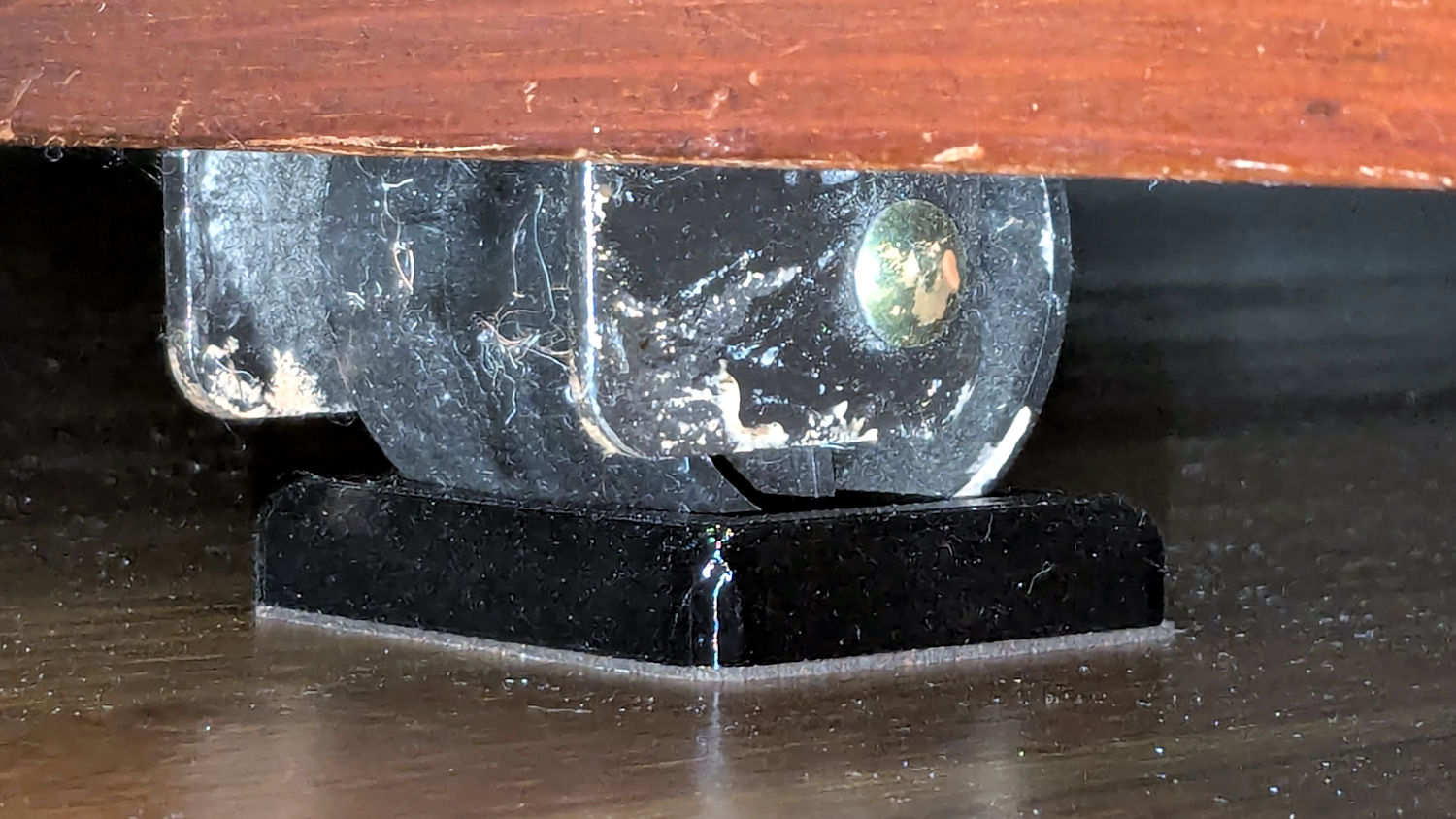
I like the wood-grain effect of the doubly curved recess on printed plastic layers, even if nobody will ever see it:

The OpenSCAD code also exports a projection of the block as an SVG file to laser-cut the cork pad.
Roll the trundle bed into position, push the stops against the wheels, lift and pull forward an inch, let it down, and the wheels snap into those recesses.
These are considerably fancier than some of the other wheel stops / feet around the house, if only because I got to use the Chord Equation to solve for the radius of the circle parallel to the axle for a snug socket.
The OpenSCAD source code as a GitHub Gist:
| // Rolling Bed roller stops | |
| // Ed Nisley – KE4ZNU | |
| // 2025-06-16 | |
| include <BOSL2/std.scad> | |
| Layout = "Show"; // [Show,Build,Roller,Plan] | |
| /* [Hidden] */ | |
| HoleWindage = 0.2; | |
| Protrusion = 0.1; | |
| ID = 0; | |
| OD = 1; | |
| LENGTH = 2; | |
| WallThick = 10.0; // default width for things | |
| BaseThick = 3.0; // bottom thickness | |
| RollerOA = [47.2,49.8,40.0]; // min & max dia, length | |
| FrameClearance = 11.0; // max height under bed frame at roller | |
| PadOA = [RollerOA[LENGTH] + 2*WallThick,RollerOA[OD],FrameClearance – 1.0]; | |
| //———- | |
| // Define Shapes | |
| module Roller() { | |
| m = (RollerOA[OD] – RollerOA[ID])/2; | |
| RollerR = (m^2 + (RollerOA[LENGTH]^2)/4) / (2*m); | |
| up(RollerOA[OD]/2) | |
| yrot(90) | |
| rotate_extrude($fa=1) | |
| intersection() { | |
| left(RollerR – RollerOA[OD]/2) | |
| circle(r=RollerR,$fa=1); | |
| rect([RollerOA[OD]/2,RollerOA[LENGTH] + 2.0],anchor=LEFT); | |
| } | |
| } | |
| module RollerStop() { | |
| difference() { | |
| cuboid(PadOA,anchor=BOTTOM,rounding=WallThick/2,except=BOTTOM); | |
| up(BaseThick) | |
| Roller(); | |
| } | |
| } | |
| //———- | |
| // Build things | |
| if (Layout == "Plan") { | |
| projection(cut=true) | |
| RollerStop(); | |
| } | |
| if (Layout == "Roller") { | |
| Roller(); | |
| } | |
| if (Layout == "Show") { | |
| RollerStop(); | |
| color("Green",0.5) | |
| up(BaseThick) | |
| Roller(); | |
| } | |
| if (Layout == "Build") { | |
| RollerStop(); | |
| } |