This carton went through the date coder with its lid open:

They made a fine breakfast …
The Smell of Molten Projects in the Morning
Ed Nisley's Blog: Shop notes, electronics, firmware, machinery, 3D printing, laser cuttery, and curiosities. Contents: 100% human thinking, 0% AI slop.

This carton went through the date coder with its lid open:
They made a fine breakfast …

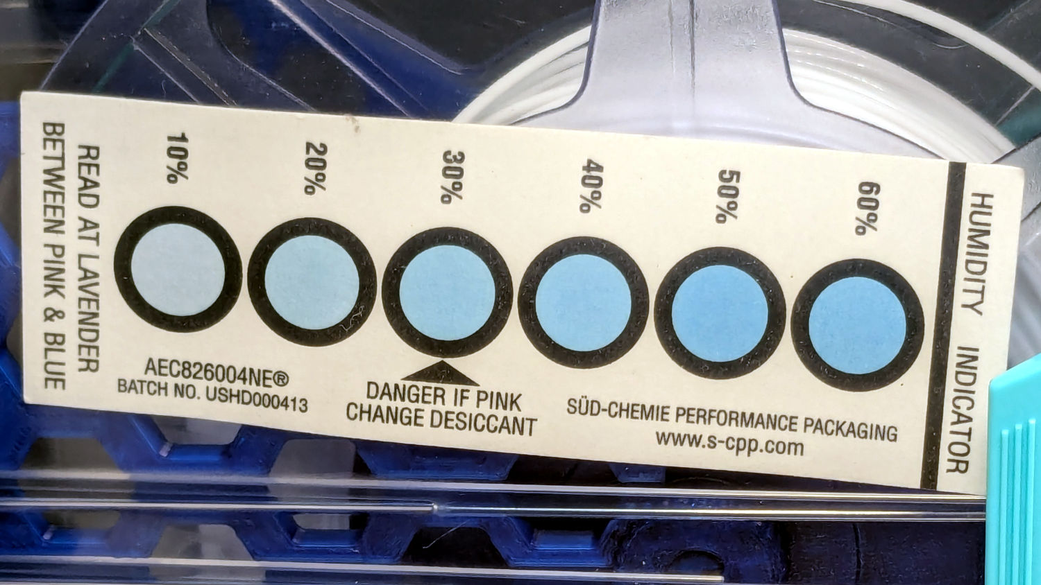
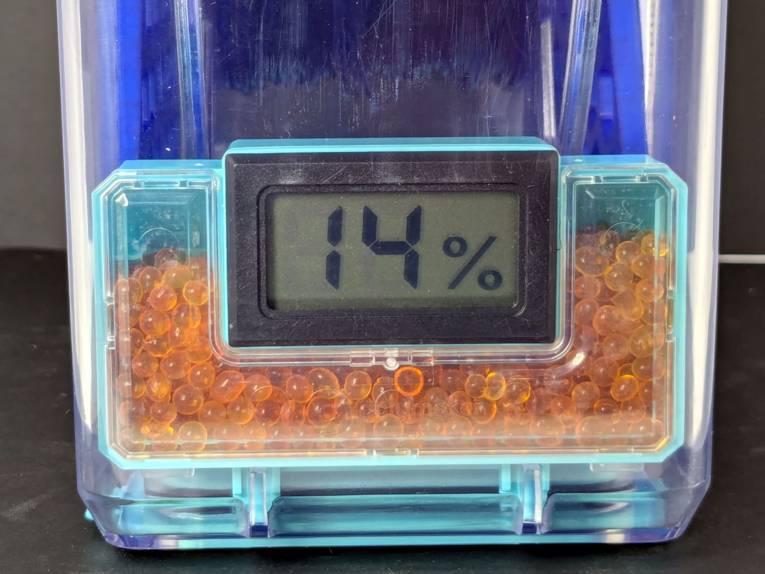
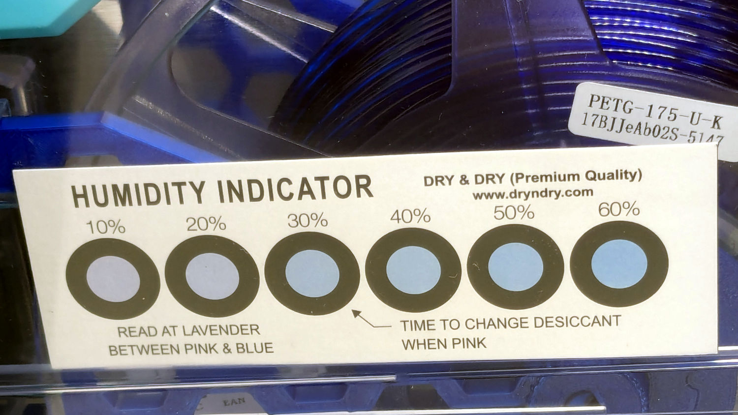
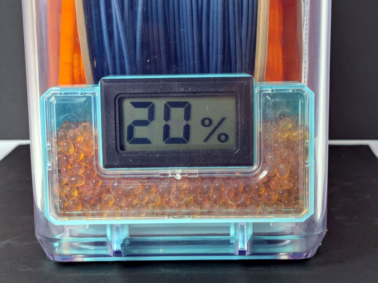
A week after installing 25 g of fresh silica gel, without any outside influence other than using some of the filaments to build things, I recorded the humidity meter reading, the indicator card colors, and the weight gain.
Click on any picture for more dots and to get rid of the captions and their stylin’ photo-blur.
White PETG, gain 0.6 g:

Black PETG, gain 0.8 g:

Orange PETG, gain 1.0 g:

Blue PETG, gain 0.4 g:
Blue PETG-CF, gain 1.3 g:
Black PETG-CF, gain 2.1 g:

Gray PETG-CF, gain 2.1 g:
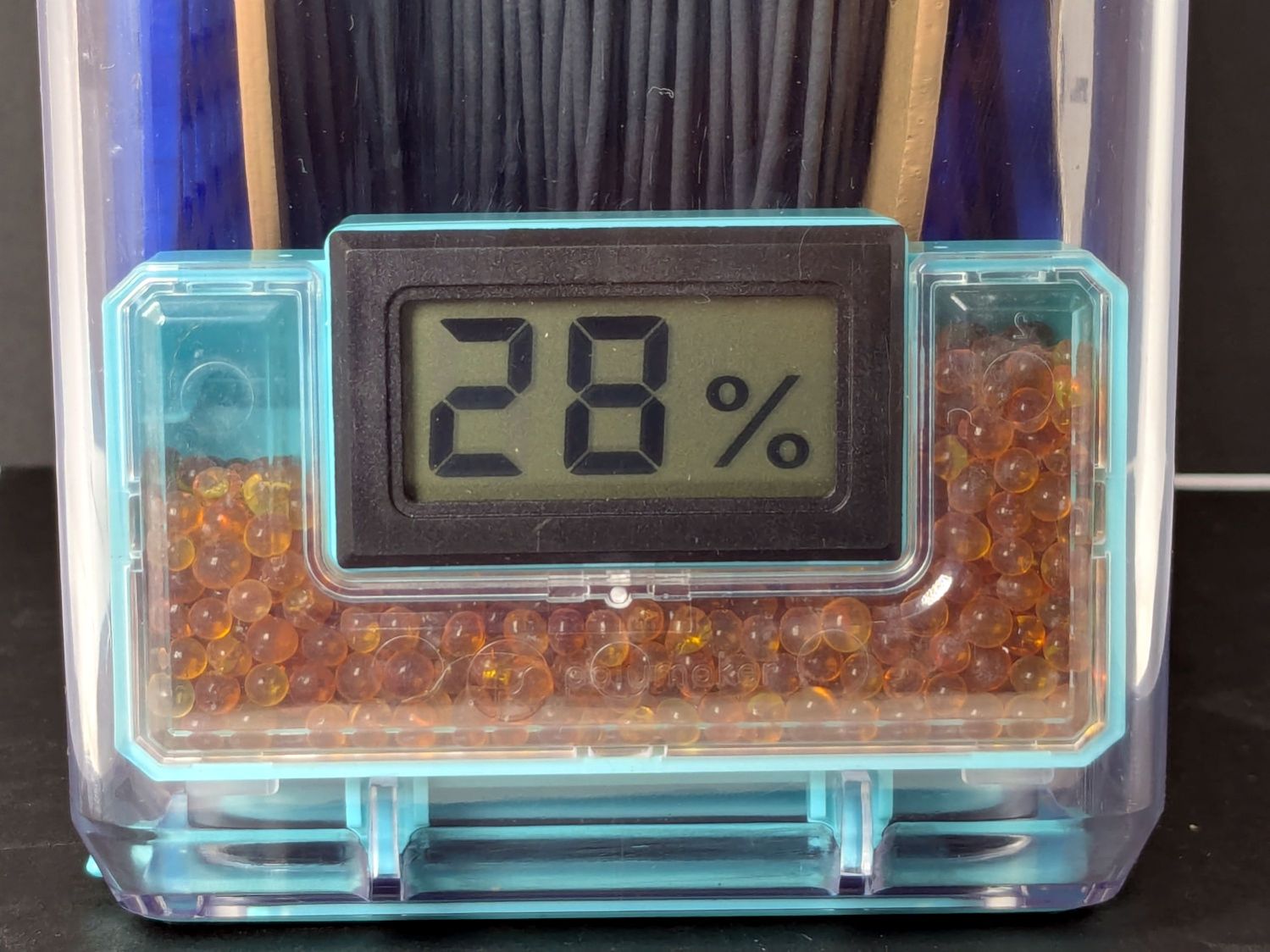
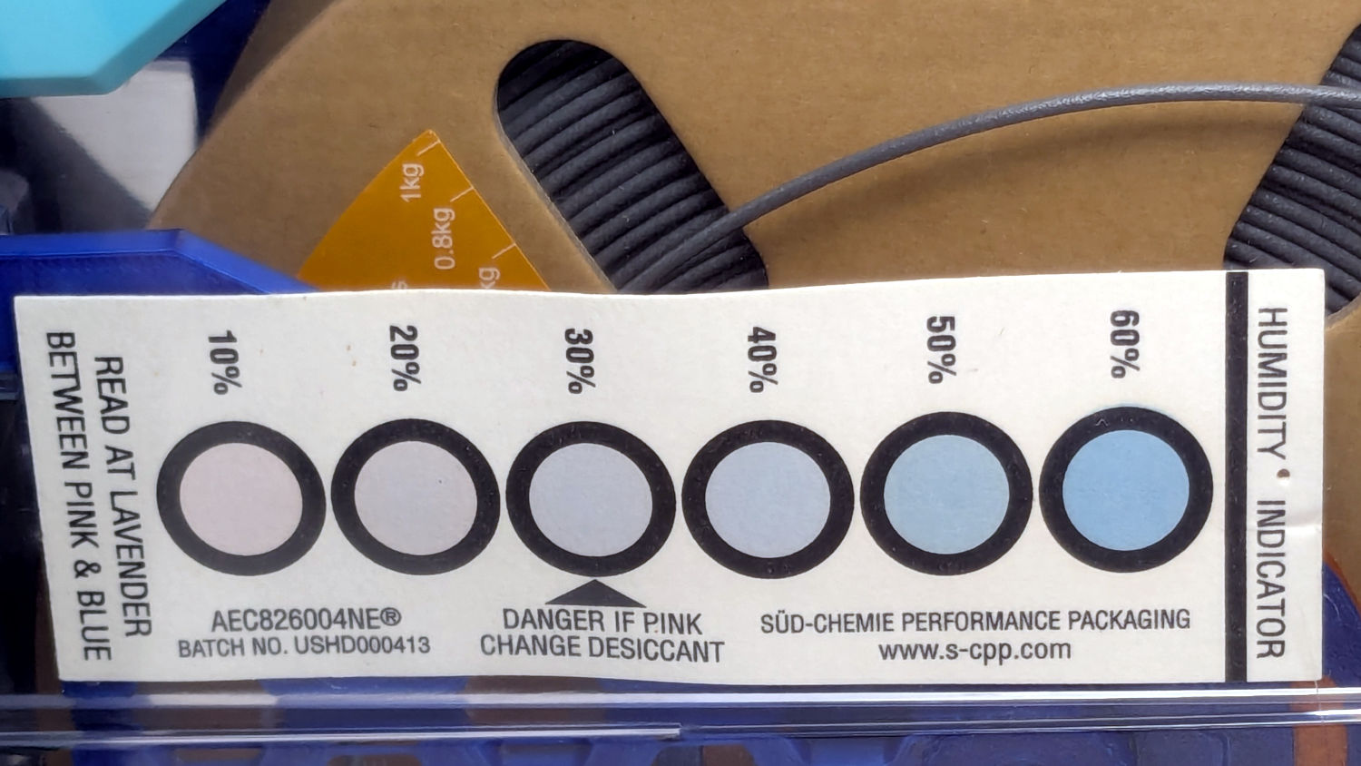
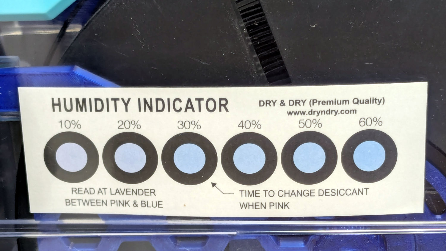
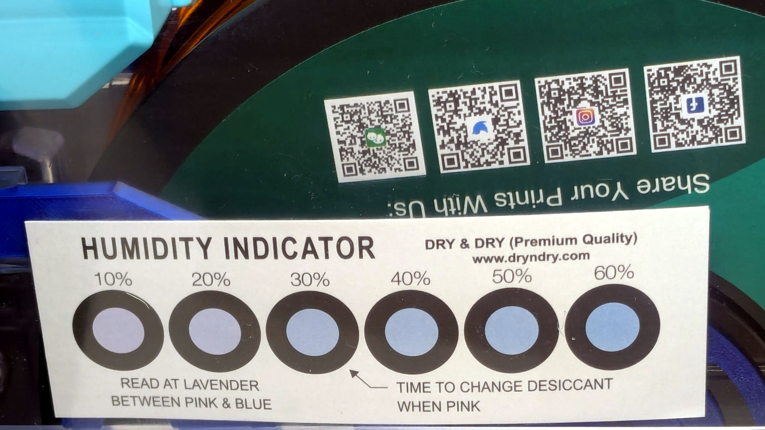
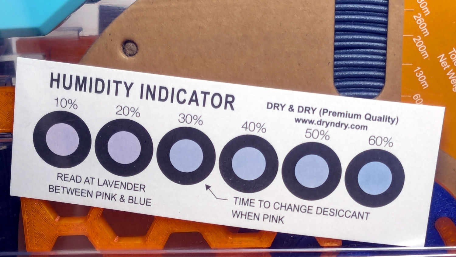
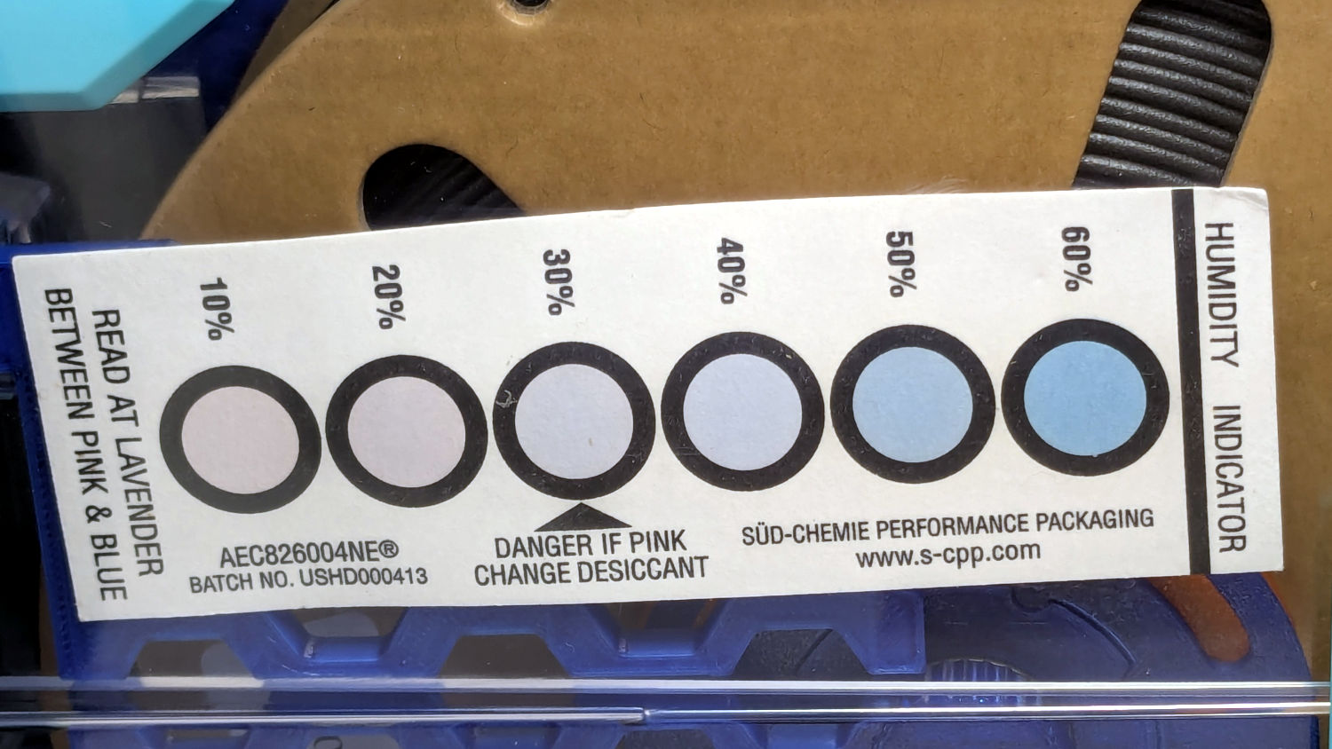
The (newer) indicator cards with the smaller dots / larger black borders seem less acute than the (older) large-dot cards. The two 28 %RH cards look about right, but the 20 and 21 %RH cards seem more different than the similar humidity would suggest.
Under 20 %RH, all the spots look pretty much the same, but AFAICT any humidity below 20 %RH is Good Enough for 3D printing.
The Blue PETG-CF went directly from its sealed bag into the PolyDryer box, unlike the Black and Gray PETG-CF spools that sat in the 50% RH basement long enough to soak up the ambience. The Blue has outgassed enough water to suggest spools do not arrive “bone dry” from the factory, although the Black and Gray prove the Basement Shop is wetter than the factory.
All of the silica gel together weighed 184.2 on the same scale I originally measured the 25 g quantities that should have totalled 175 g, but the individual measurements total 183.3 g. I don’t trust the scale to be better than ±0.1 g on any measurement, so half a percent is likely as good as it gets.
The silica gel weighed 187 g on the kitchen scale, sweated down to 179 g after 7 minutes in the microwave being defrosted like 1.5 pounds of fish, and, depending on which numbers you believe, released 8 to 10 g of water in the process.
Microwaving something containing so little water means the silica gel absorbs very little of the energy: the dish, glass turntable, and metal walls got absurdly hot. I think using the induction cooktop and cast iron pan makes more sense, even if it takes longer.
With fresh silica gel in place, perhaps waiting two weeks will produce interesting numbers.

A recent quilt photo shoot degenerated into me chasing several bright orange clamp jaws across the deck as they popped off their clamps hanging from the photo backdrop scaffold. Most clamps have jaws snapping onto actual rods, but these clamps have molded-in-place “rods” much smaller than the 2 mm expected by the jaws and much more irregular than seems reasonable.
Trace and scan the nose of a clamp:

Curiously, the molded rod is not centered in the nose:

Use LightBurn to coerce a scan of the first sketch into a suitable path, laser-cut some MDF, and glue up a drill fixture:
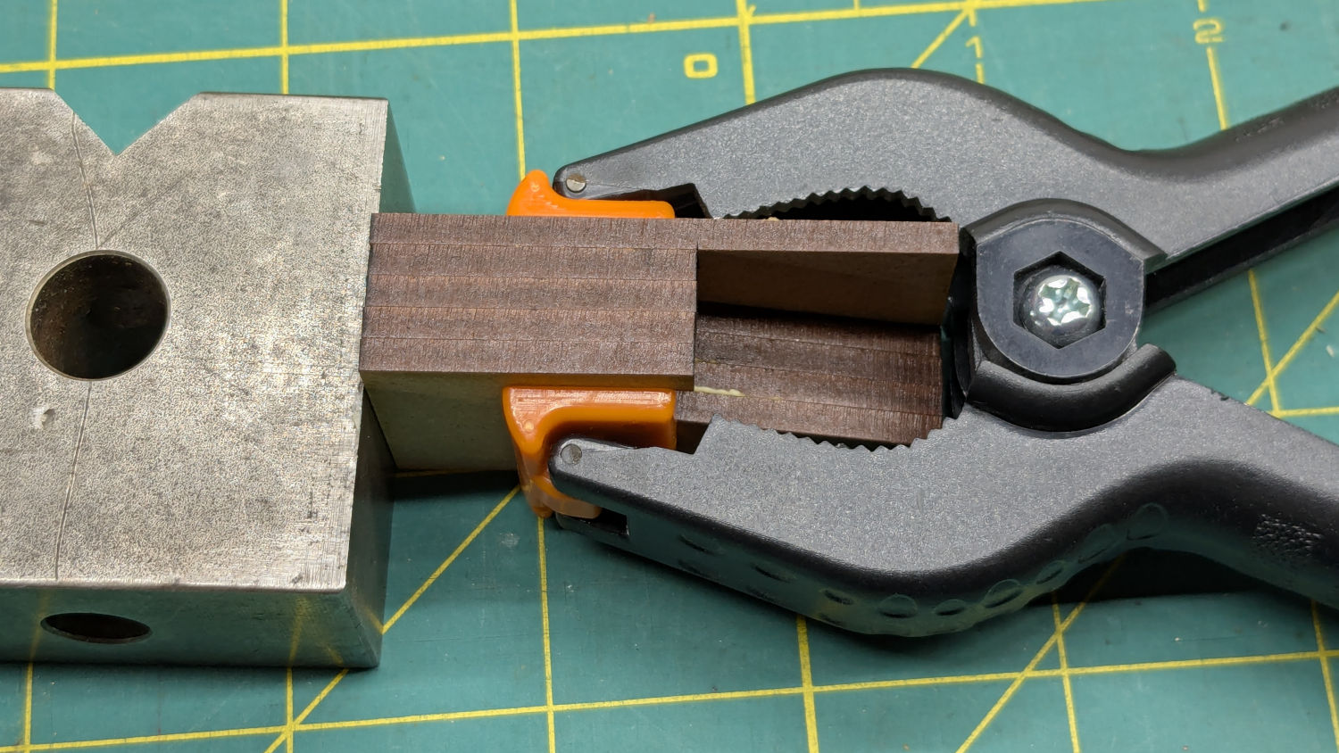
Align the drill to the center of the off-center hole marked on the bottom layer:

The drilling setup looks casual, but hand-holding the clamps against the rear wall and into the form-fitting nose recess sufficed:

I snipped the plastic “rods” out before drilling the holes, then rammed 2 mm steel rods in place:

They’re really 5/64 inch = 1.98 mm rods from the oil-hardening drill rod stash, but entirely sufficient for the purpose.
With one clamp in hand, though, there was obviously no reason for the rods to be off-center. So I centered the drill in the nose, punctured the rest of the clamps, and pressed 2 mm carbon fiber rods in place:

The rods were cut to 20 mm by rolling them across a pad with firm pressure from a utility knife. That was mostly to get some experience cutting carbon fiber, which is obviously overqualified for the job.
Snap the orange jaws in place and I shall never suffer the embarrassment of chasing them again …
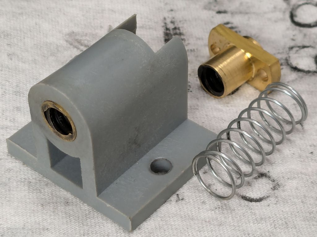
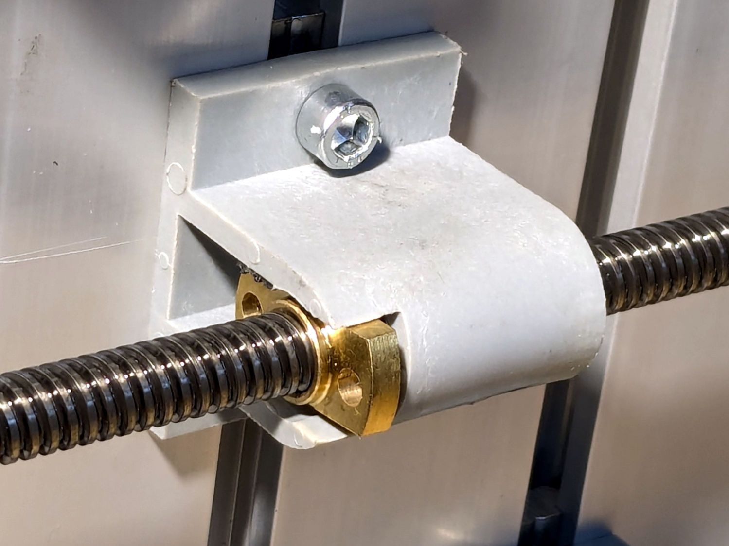
A confluence of unrelated events led me to unboxing and setting up the CNC-3018XL most recently used to plot Homage Tek Circuit Computer decks, but the table slid along its rods entirely too easily. A peek at the leadscrew revealed an assortment of parts last seen when I extended the frame:

The featureless cylinder is the leadscrew follower nut, which evidently popped out of its proper place in the table drive block:

The crude chamfer suggests that end went into the block first, so that’s what I did:

It seems snug enough in there, at least for a machine used solely for plotting and maybe drag knife cuttery, so I’ll assume the box received some rough handling during our move.
It’s now back in place and seems to work well enough:
I briefly considered adding some setscrews to hold it in place, but came to my senses. If it pops out again, maybe it’ll be time to rebuild that block with proper retention.
The software side of the thing surely needs TLC, too.

For reasons I do not profess to understand, GIMP 3.0 does not work with plugins written for GIMP 2.0, including the XSane plugin that handles scanning. This seems like an obvious oversight, but after three months it also seems to be one of those things that’s like that and that’s the way it is.
Protracted searching turned up gimp-xsanecli, a GIMP 3.0 plugin invoking XSane through its command-line interface to scan an image into a temporary file, then stuff the file into GIMP. Unfortunately, it didn’t work over the network with the Epson ET-3830 printer / scanner in the basement.
It turns out gimp-xsanecli tells XSane to output the filename it’s using, then expects to find the identifying XSANE_IMAGE_FILENAME string followed by the filename on the first line of whatever it gets back:
if result != 'XSANE_IMAGE_FILENAME: ' + png_out:
  Gimp.message('Unexpected XSane result: ' + result)
  return Gimp.ValueArray.new_from_values([GObject.Value(Gimp.PDBStatusType, Gimp.PDBStatusType.EXECUTION_ERROR)])
The font ligature that may or may not mash != into ≠ is not under my control.
Protracted poking showed the scanner fires a glob of HTML through proc/stdout into gimp-xsanecli before XSane produces its output, but after the scan completes:
<!DOCTYPE HTML PUBLIC "-//W3C//DTD HTML 4.01//EN "
"http://www.w3.org/TR/html4/strict.dtd">
<html>
<head>
… snippage …
</head>
<body><noscript>Enable your browser's JavaScript setting.</noscript></body></HTML>XSANE_IMAGE_FILENAME: /tmp/out.png
Complicating the process:
gimp-xsanecli expectsSo …
Insert a while loop into the main loop to strip off the HTML glob line by line by line:
        while True:
                # Wait until XSane prints the name of the scanned file, indicating scanning is finished
                # This blocks Python but that is ok because GIMP UI is not affected

                # discard HTML header added by scanner to first scan
                while True :

                        result = proc.stdout.readline().strip()

                        if r'</body>' in result :
                                result = result.partition(r'</HTML>')[-1]
                        #        Gimp.message('Found end of HTML: ' + result)
                                break

                        elif 'XSANE_IMAGE_FILENAME:' in result :
                        #        Gimp.message('Found filename: ' + result)
                                break

                        else :
                        #        Gimp.message('Discarding: ' + result)
                                continue

                if result == '':
                        # XSane was closed
                        break

                if result != 'XSANE_IMAGE_FILENAME: ' + png_out:
                        Gimp.message('Unexpected XSane result: ' + result)
                        return Gimp.ValueArray.new_from_values([GObject.Value(Gimp.PDBStatusType, Gimp.PDBStatusType.EXECUTION_ERROR)])

                # Open image
                image = Gimp.file_load(Gimp.RunMode.NONINTERACTIVE, Gio.File.new_for_path(png_out))
                Gimp.Display.new(image)

                # Remove temporary files
                os.unlink(png_out)

                if not SCAN_MULTIPLE:
                        proc.terminate()
                        break

        os.rmdir(tempdir)

        return Gimp.ValueArray.new_from_values([GObject.Value(Gimp.PDBStatusType, Gimp.PDBStatusType.SUCCESS), GObject.Value(Gimp.Image.__gtype__, image)])
While it’s tempting to absorb the whole thing in one gulp with proc.stdout.read().strip(), that doesn’t work because nothing arrives until the XSane subprocess terminates, which is not what you want.
A scan to show It Just Works™ :
I expect it doesn’t work under a variety of common conditions, but … so far so good.

A pair of the 2022 batch of Newmowa NP-BX1 lithium batteries for the Sony AS-30V helmet camera no longer survive a typical hour-long bike ride:
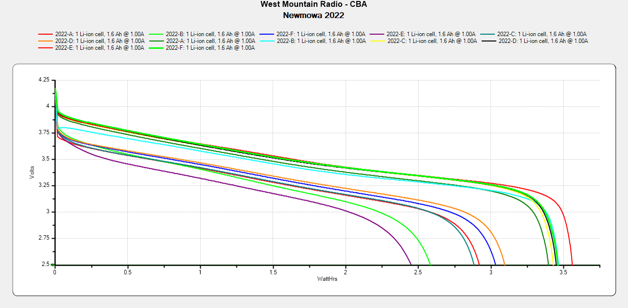
The best four have a capacity down 14% from the good old days and the weakest pair are down 29%.
The camera uses 1.9 W, so a battery with 2.5 W·hr capacity should last 78 minutes, but about 400 mV of voltage depression causes the camera to give up before using its full capacity.
So they have a useful lifetime of maybe two years in our regular bike riding schedule and I should have bought replacements last year. I hope the next batch isn’t New Old Stock or recycled cells.

Having accumulated a bunch of used activated alumina desiccant, I figured now was a good time to try regenerating it. Industrial applications use dry gas and very high temperatures, but perhaps holding it over 100 °C for a few hours will suffice for my purposes.
I pressed our daily driver cast iron skillet and induction cooktop into service:

After an hour the surface temperature was around 150 °F, so I covered the pan with a water-cooled lid to see if any vapor condensed on it:
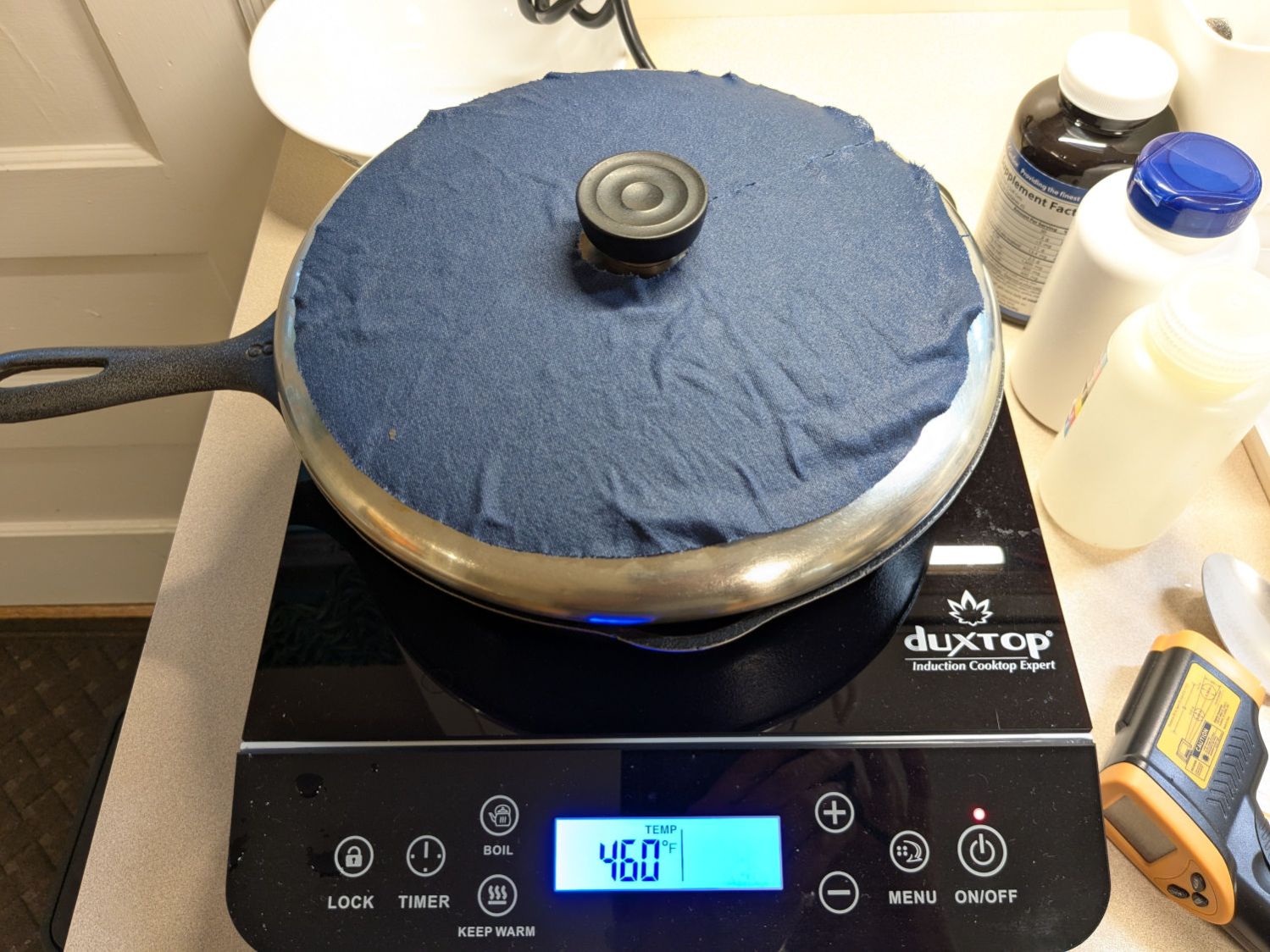
It did, indeed, so I alternated covering and exposing the pan, which was likely a waste of my time, until the alumina dried enough that the lid didn’t collect any condensation. The whole process took just under four hours with the cooktop set to its maximum of 460 °F for most of the time.
The beads then cooled to room temperature in a covered dish:

The beads weighed 626 g at the start of the adventure and sweated down to 593 g, parting with 33 g = 1.2 oz of water in the process for a loss of 5.6%. I have no idea how dry they are now, but they’re an ounce drier than before.
