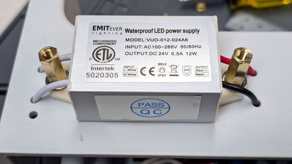
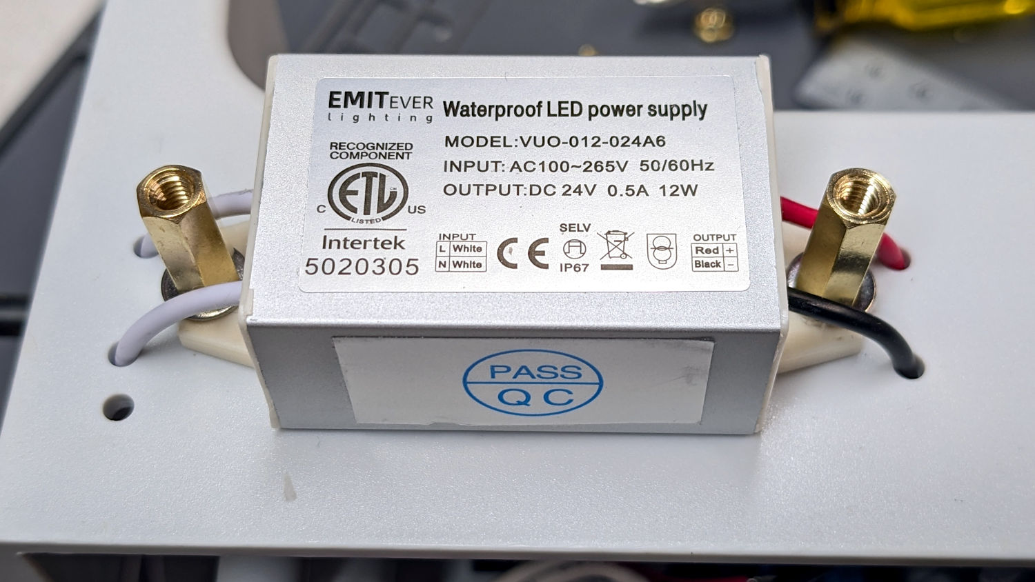
With the quilt off the HQ Sixteen, I could install the 24 V power supply for the Nose Ring Lights:
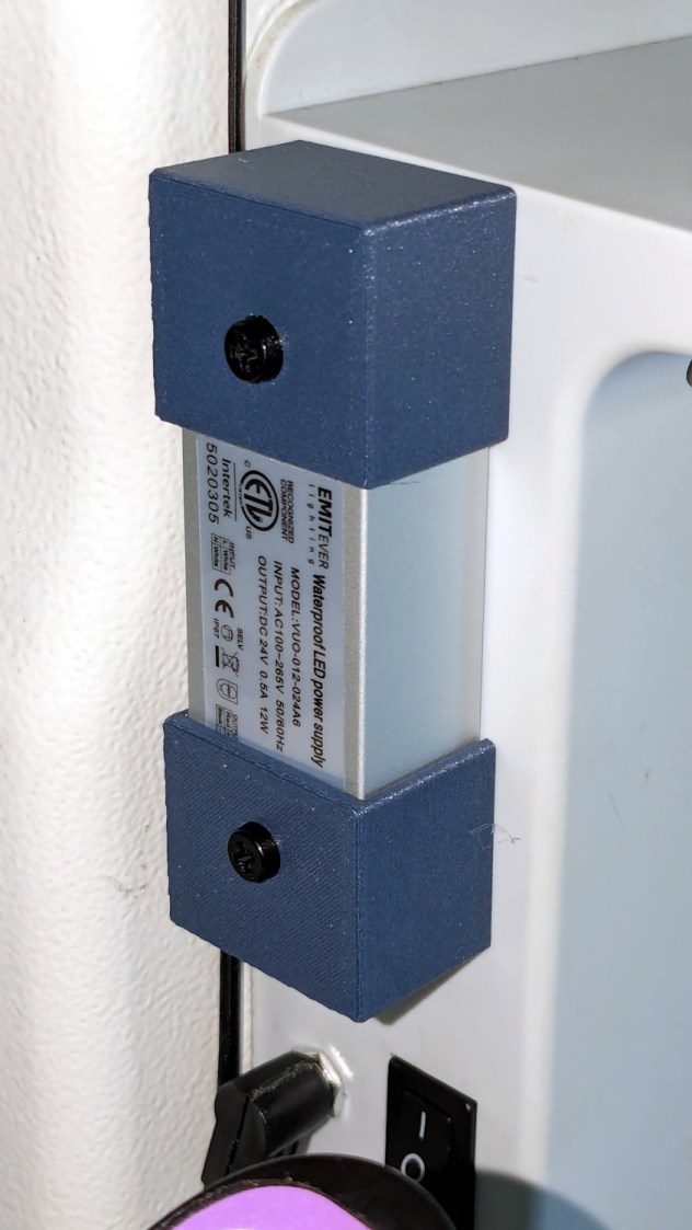
IMO, black nylon screws look spiffier than brass.
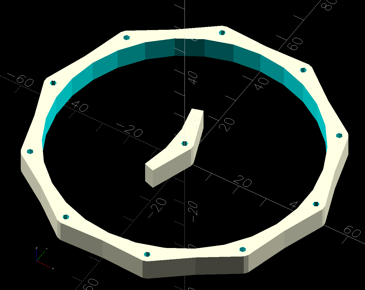
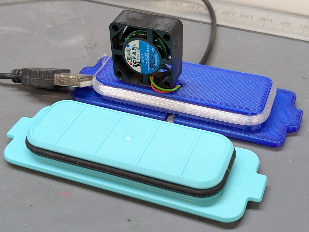
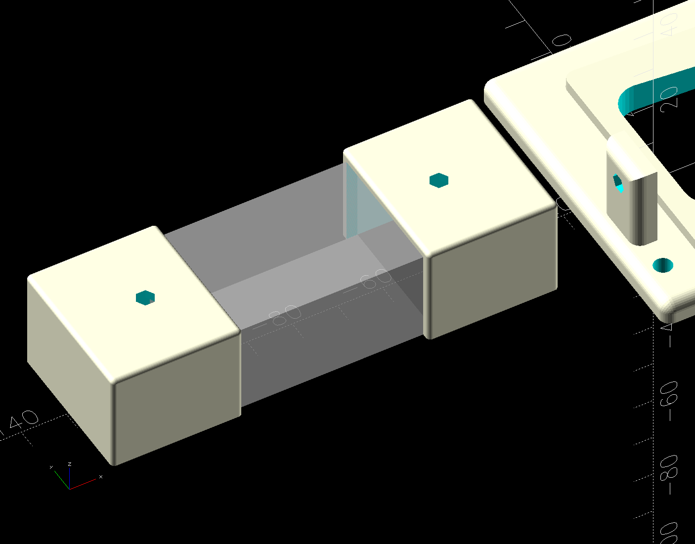
The solid model shows the covers have a 2 mm overlap with the power supply case to keep them lined up:
I managed to reuse three of the five holes from the previous 12 V power supply and drill only three more:
The tops of the power supply ears aren’t quite flat, giving the standoffs a slight tilt that the covers mostly drag back into alignment.
The M4 brass standoffs screw into holes tapped in the thick plastic, thus eliminating nuts inside the power pod:

The yellow silicone tape wraps two pairs of Wago connectors that dramatically simplify electrical connections in anything with enough space for their chonky bodies.
In the unlikely event you need such things, the original post links the OpenSCAD source code.
With the power supply in place, I think I can put some LED strips under the arm of the machine to light up more of the quilt than the nose lights can reach. More pondering is in order.