Ed Nisley's Blog: Shop notes, electronics, firmware, machinery, 3D printing, laser cuttery, and curiosities. Contents: 100% human thinking, 0% AI slop.
The Protoneer CNC Shield has headers for two endstops on each axis, although they’re wired to the same Arduino input pin. I installed a pair of Makerbot-style endstops on the Y axis, plugged them in, triggered one, and … the Arduino crashed. Hard. As in, a complete loss of power and reboot.
Some fiddling around produced absolutely baffling symptoms, as I replaced each endstop board and their cables to no avail.
Perusing the schematic (the “full instructions” link is dead, of course) eventually revealed the problem:
Makerbot style endstop – schematic
Got it?
Although there’s a pullup on the COM switch terminal, the switch’s NC terminal is connected to the +5 V supply, shorting across the both resistor and the LED+resistor. With two endstops in parallel, triggering one crowbars the other’s power supply to ground. I’m sure it made sense at the time, perhaps by ensuring no possible noise source could interfere with the pullup.
The solution is simple: disconnect the NC terminal from the power supply. As it turns out, the PCB layout routes +5 V on the bottom layer, up through the via around the NC switch terminal, thence to the LED and resistor, leaving only one choice:
MPCNC – dual MG endstop hack
Yup, amputate the NC terminal and be done with it.
After that, the pullup resistor lets the endstops cooperate like you’d expect: triggering either one lights up both LEDs.
The default MPCNC configuration wires the two stepper motors on each axis in series, doubling the total resistance and inductance of a single motor. The stock Automation Technology motor presents 2.8 Ω and 4.8 mH in each winding to the driver, for an L/R time constant of τ = 1.7 ms. Doubling both doesn’t change the ratio, but including the harness wiring resistance gives 1.6 ms = 9.6 mH / 6 Ω.
The default DRV8825 driver configuration uses 1:32 microstepping, which I thought was excessive. I replaced the stock RAMPS setup with a Protoneer / GRBL setup using A4988 drivers in 1:16 microstepping mode, got it configured, and made a few measurements:
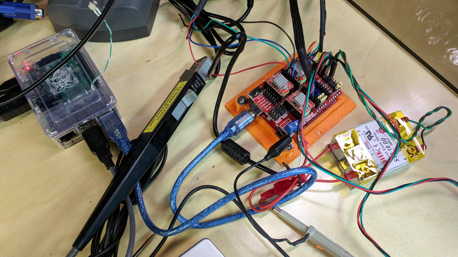
MPCNC CNC Shield – Current Measurement Setup
The current probe measures the winding current in the red wire. The voltage probe at the bottom isn’t doing anything, because I ran out of hands.
Here’s a 10 mm X axis move at 3600 mm/min = 60 mm/s:
MPCNC X 10mm 60mm-s 500mA-div
The top trace shows the winding current at 500 mA/div. The bottom trace shows the voltage applied to the winding at the A4988 driver pin.
Basically, the +12 V supply doesn’t provide enough headroom to let the driver force the required current into the winding at full speed, which is why the peak current decreases as the step rate increases and the sinusoid becomes a square(-ish) wave. The applied voltage switches rapidly to maintain the proper winding current when the axis is stationary or moving slowly (where the driver’s PWM current control works fine), but turns into a square (well, rectangular) wave as the pace picks up (and the driver loses control of the current).
The motor drives a 16 tooth pulley with a 2 mm belt pitch, so each revolution moves 32 mm of belt. With 1:16 microstepping, each revolution requires 3200 = 200 full step × 16 microstep/step pulses, which works out to 100 step/mm = (3200 step/rev) / (32 mm/rev). At the commanded speed near the middle of the trace, the driver must produce 6000 step/s = 60 mm/s × 100 step/mm, so each step lasts 167 μs, about τ/10.
In round numbers, the first full cycle on the left has a 20 ms period. Each full cycle = 4 full steps = 64 microsteps, so the belt moved (60 step) / (100 step/mm) = 0.6 mm, at an (average) speed of 30 mm/s = 1800 mm/min. The current begins to fall off by the third cycle with a 12 ms period, a pace of 50 mm/s = 3000 mm/s, and pretty much falls off a cliff by 60 mm/s in the middle.
To be fair, those are aggressive speeds for milling, but lasers and 3D printers tick along pretty quickly, so they’re not unreasonable.
“High Endurance” means it’s rated for 5000 hours of “Full HD” recording, which they think occurs at 26 Mb/s. The Fly6 records video in 10 minutes chunks, each weighing about 500 MB, call it 1 MB/s = 8 Mb/s, a third of their nominal pace. One might reasonably expect this card to outlive the camera.
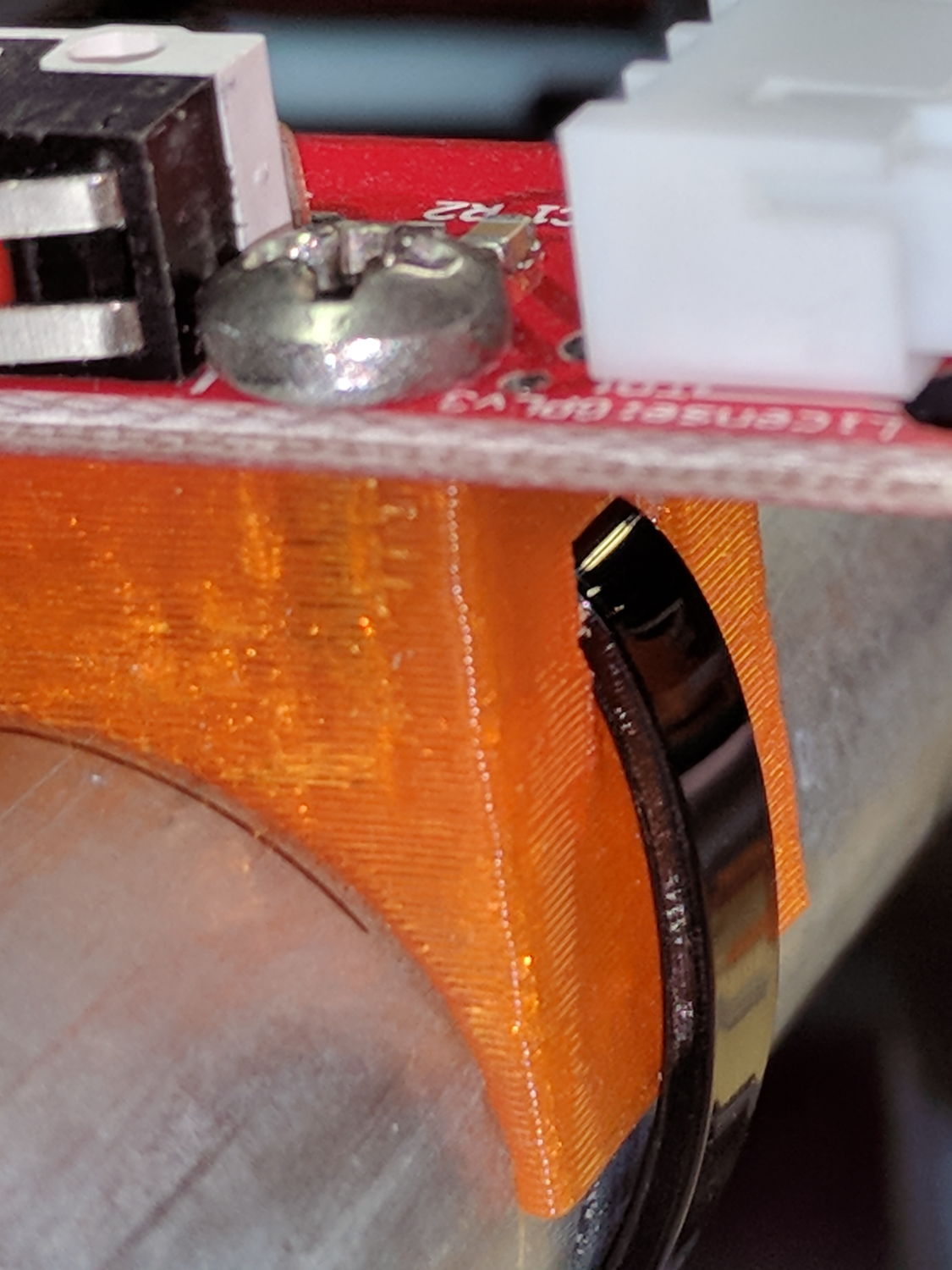
On the other side, a ramp helps bend the tie toward the MPCNC rail:
X min endstop – recessed strap
Which looks thusly in the realm of applied mathematics:
MPCNC MB Endstop Mount – strap recess
I’ll leave the OpenSCAD code to your imagination, because the endstop block turns out to be a bit small for the recesses. Eventually, they need a dust cover and some cleanup.
This story unfolded over the course of three weeks:
USPS Tracking
After the package visited Poughkeepsie for the second time, I contacted the local delivery manager. He was absolute baffled as to what was going on, but promised to intercept it and give me a call when it returned.
When I called on 22 November, I got somebody else who was also completely baffled. However, she could view a scan of the package and noticed an odd mismatch:
The package tracking info showed my name and street address
The tracking info had my email address
The package label had somebody else’s name & address in Rensselaer
As best as I can follow the explanation, automated routing machinery at each facility scans each incoming package and shunts it to a conveyor belt filling a bin, thence to a truck, and away toward wherever it’s going. Alas, the (bogus) tracking info associated with this particular package aimed it toward me in Poughkeepise, but, when it arrived, a human read the actual label and tossed it in the bin headed toward Rensselaer.
Upon arriving in Renselaer, the automation fired it back toward Poughkeepsie.
Lather, rinse, repeat.
I buy plenty of “made in China” things, many shipped with tracking numbers, and tracking generally works the way you’d expect. Sometimes, however, the shipper does not tell me the tracking number and the first I learn of it is when tracking emails begin arriving from USPS. In other cases, no USPS facility along the way scans the package, whereupon the first notification I get happens when I open my mailbox and see the package.
In this case, I hadn’t bought anything close to the time when it would have been shipped and the tracking number didn’t correspond to any of my orders.
If this were an isolated incident, I’d shrug it off, but over the last year or two this is the third or fourth time this has happened, with packages from different Chinese sellers and another shipped from Arizona to Tennessee.
There was also a certified mail piece addressed to somebody at a nearby (easily typo-ed) address, delivered to our mailbox, but tracked as “handed to resident”. Whoops, indeed.
In all those cases, I got the tracking information from USPS, but the packages went directly to their destination. The extensive looping for this package was definitely a New Thing.
Nobody can explain how I (and my address!) get associated with these packages:
It’s obviously not a problem at the source, as I have no idea who the sellers / shippers are
To the best of my knowledge, they don’t know me, because their addresses aren’t familiar
The notices come directly from the USPS, so they’re associating me with a random package
It’s not a fault on my end, because I haven’t bought the items and don’t know they’re coming
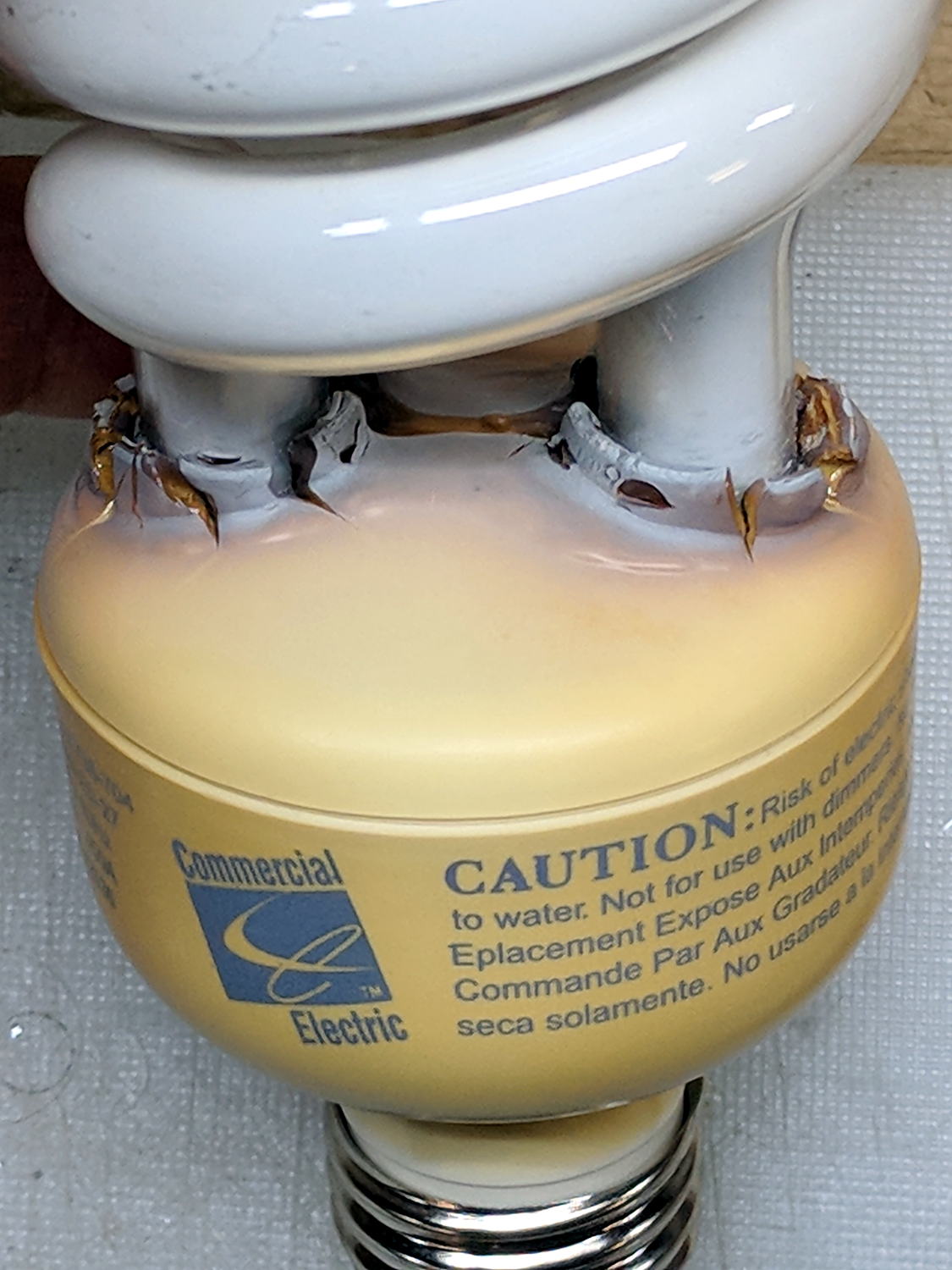
The straight-ish crack between the tube ends looks like it happened as the (yellowed) plastic ruptured and hardened.
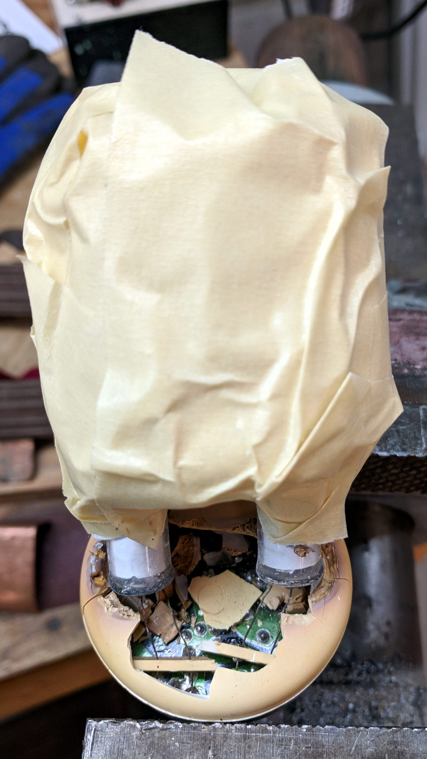
Not wanting to get a face full of glass fragments spiced with metallic mercury, I wrapped a blast shield around the spiral tube:
Failed CFL – tube wrap – shattered base
The terminal ends fit loosely in the crumbling base at the start of this operation, leaving the tube wobbling above the base. The plastic cracked as I wrapped the tube, so, for lack of anything smarter, I applied a pin punch to break away the rest of the upper base.
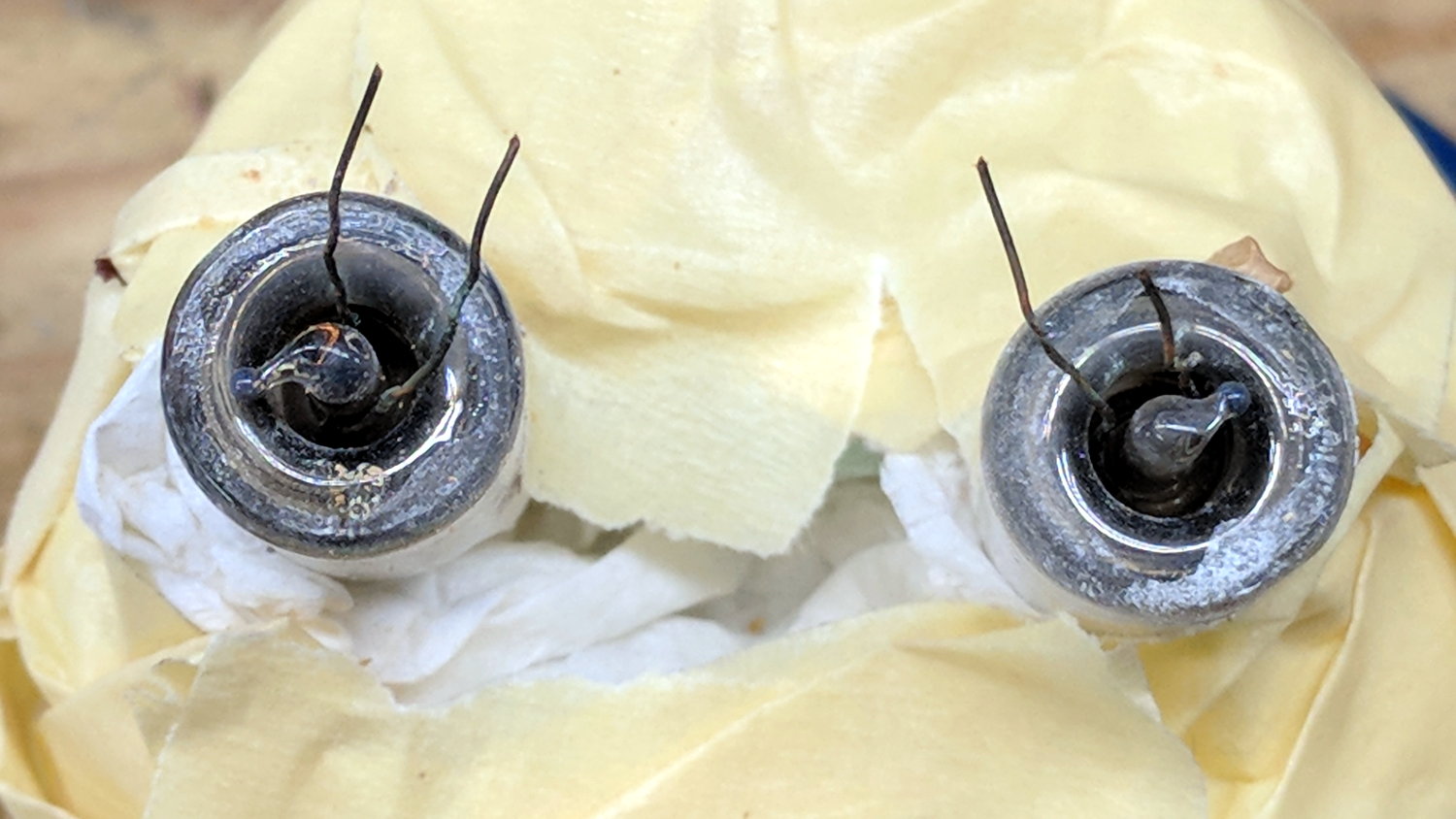
The tube doesn’t fit into a socket, of course, and terminates in four wire connections:
Failed CFL – tube terminals
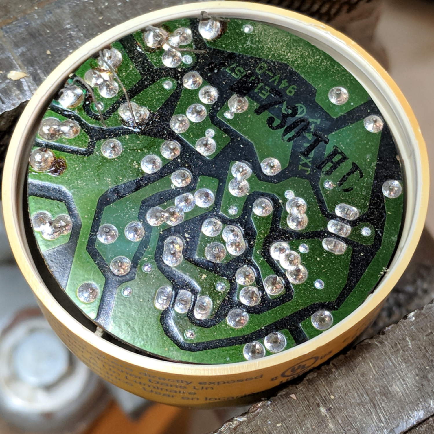
Those wires pass through notches on the edge of the PCB, bend around the board, pass through vias, and get soldered to pads. The solder side faces the tube, with all the components nestled into the base toward the screw terminals:
Failed CFL – PCB solder side faces upward
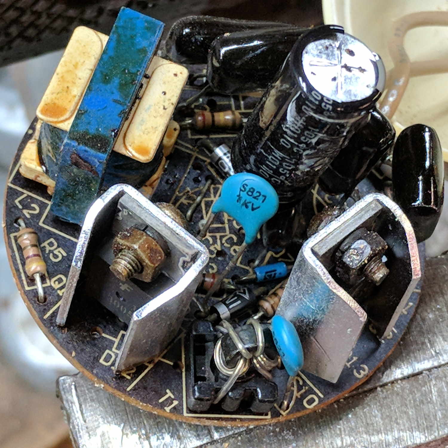
The component side sports a surprising number of parts:
Failed CFL – PCB components – 2
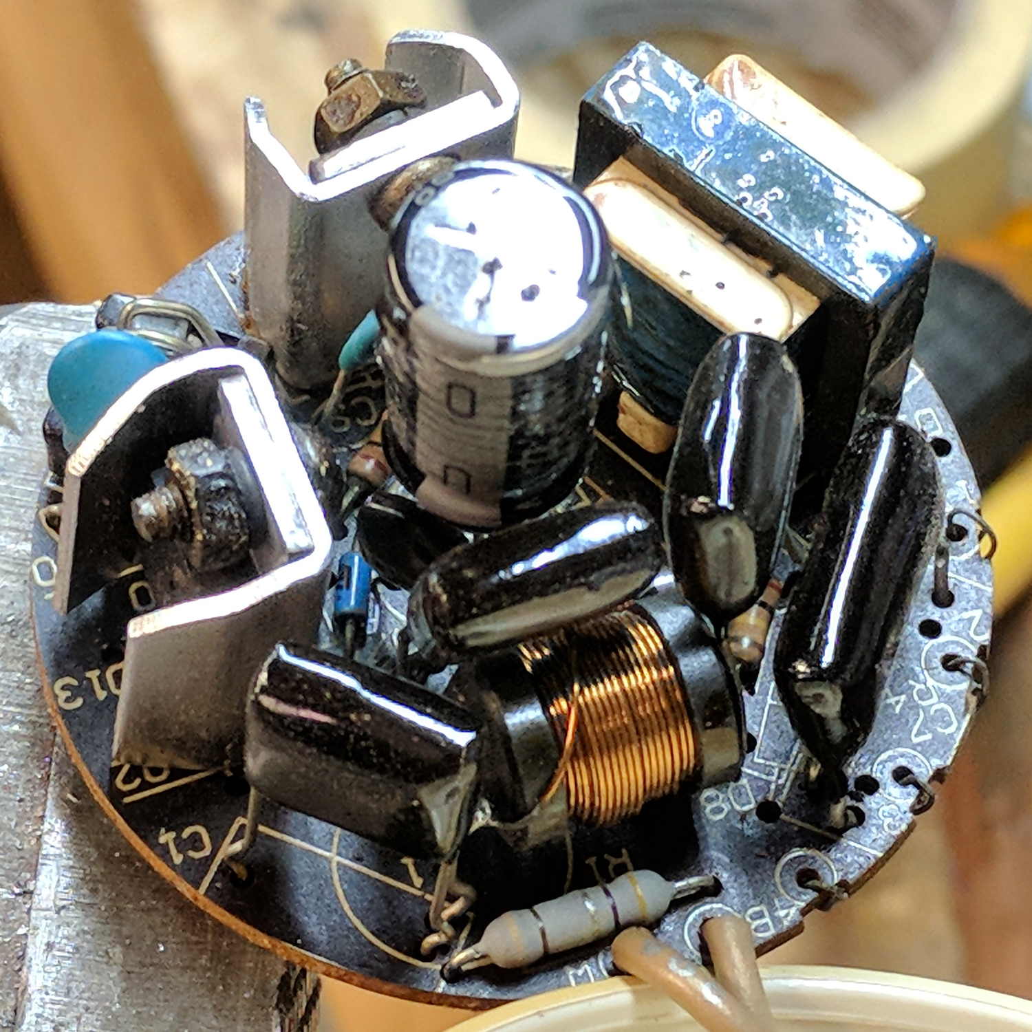
A view from the other direction, where you can see the tube wires curling around the edge:
Failed CFL – PCB components – 1
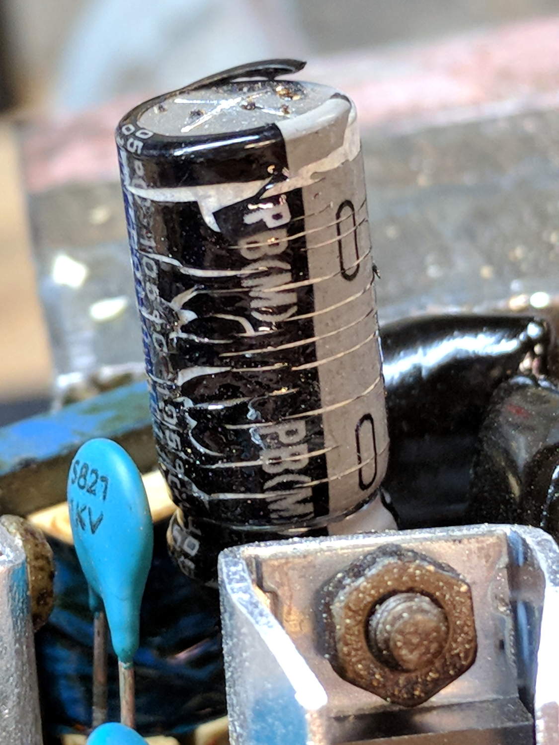
I generally harvest inductors & suchlike, but it got really really hot in there and, methinks, cooked the life out of the parts:
Failed CFL – overheated capacitor
The PCB date code stamp could be “730”, suggesting either 1997 or 2007. In any event, it’s been a while.
I hope LED bulbs outlast these things, but I have my doubts …
As part of some protracted flailing around while trying to get GNU Radio running on a Raspberry Pi 3, I discovered Raspbian defaults to a 100 MB swap file, rather than a swap partition, and everything I thought I knew about swap management seems inoperative. The key hint came from some notes on gr-gsm installation.
Tweak the /etc/dphys-swapfile config file to set CONF_SWAPFACTOR=2 for a 2 GB swap file = twice the size of the Pi’s 1 GB memory.