Ed Nisley's Blog: Shop notes, electronics, firmware, machinery, 3D printing, laser cuttery, and curiosities. Contents: 100% human thinking, 0% AI slop.
To the end of documenting colors, connectors, and connections for the MPCNC stepper motors …
At the stepper motors:
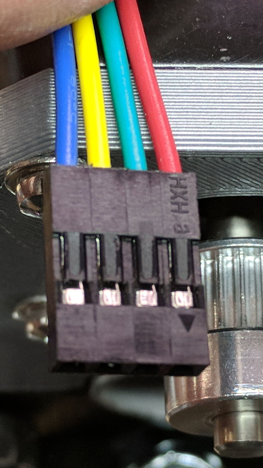
MPCNC – Stepper Connector
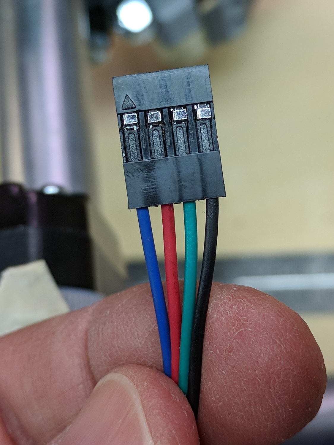
The plug for the stepper at the end of the harness:
MPCNC – Stepper Harness end connector
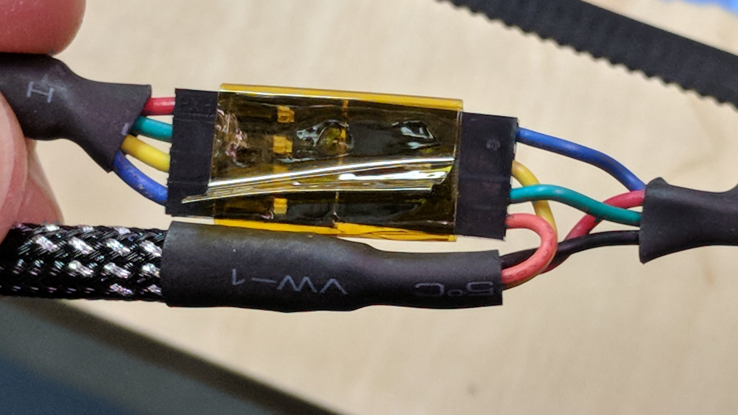
I opted to match the “pin 1” marks on the connectors, because that’s easy to remember, although it puts the pin latches on opposite sides:
MPCNC – Stepper to Harness End
Some obligatory Kapton tape holds the two connectors together.
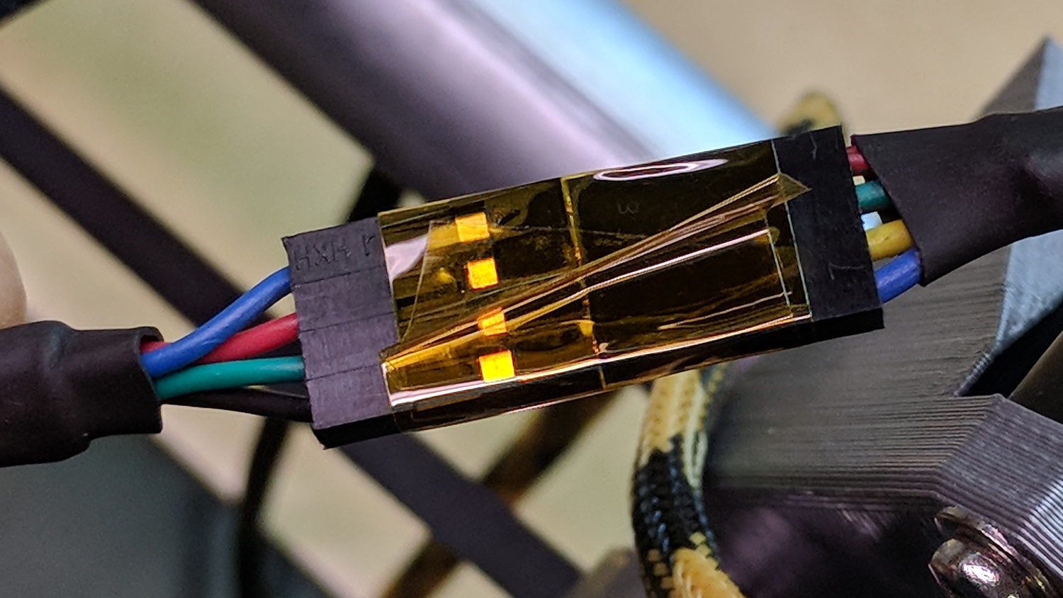
The joint at the middle of the harness, with the near-end stepper cable on the upper left:
MPCNC – Stepper Harness mid connection
At the RAMPS driver end of the cable:
MPCNC – Stepper harness – driver end
The Z-axis extension cable, with the stepper cable on the right:
MPCNC – Z stepper to extension cable
I plugged the cables into the RAMPS board with the “pin 1” mark at the A1A2 end of the connectors.
With all the wires in place (and the GT2 drive belt still in its bag), I stuck masking tape tabs on the motor shafts, connected the RAMPS board, and verified the directions:
MPCNC – Stepper motor direction test
Although the Y axis needed reversing, both pairs of motors turned in the same direction!
Being that type of guy, I reversed the Y axis direction in the firmware configuration, because it’s easier for me to make all the physical connections look the same than (try to) remember to flip the Y axis connector whenever I must reconnect the cable to the driver.
A Mostly Printed CNC machine from Vicious1 provides an easily configured platform for low-force CNC activities like plotting, vinyl cutting, PCB milling, and maybe wood / plastic / wax routing with a suitable dust vacuum / downdraft table / enclosure. Despite many videos, the notion of open-air laser cutting remains a non-starter around here.
I opted for the Parts Bundle (all the “vitamins” required, from RAMPS controller to locknuts, to assemble the machine) and the Printed Parts Bundle (all the printed components), then picked up four 10 foot lengths of 3/4 inch ID = 23.5 mm OD galvanized steel conduit locally. Yes, I have a 3D printer, but the notion of feeding two spools of plastic through it over the course of 100++ printing hours, plus figuring out how to get the tolerances right, convinced me to regard this as a kit project, not a design-and-build project.
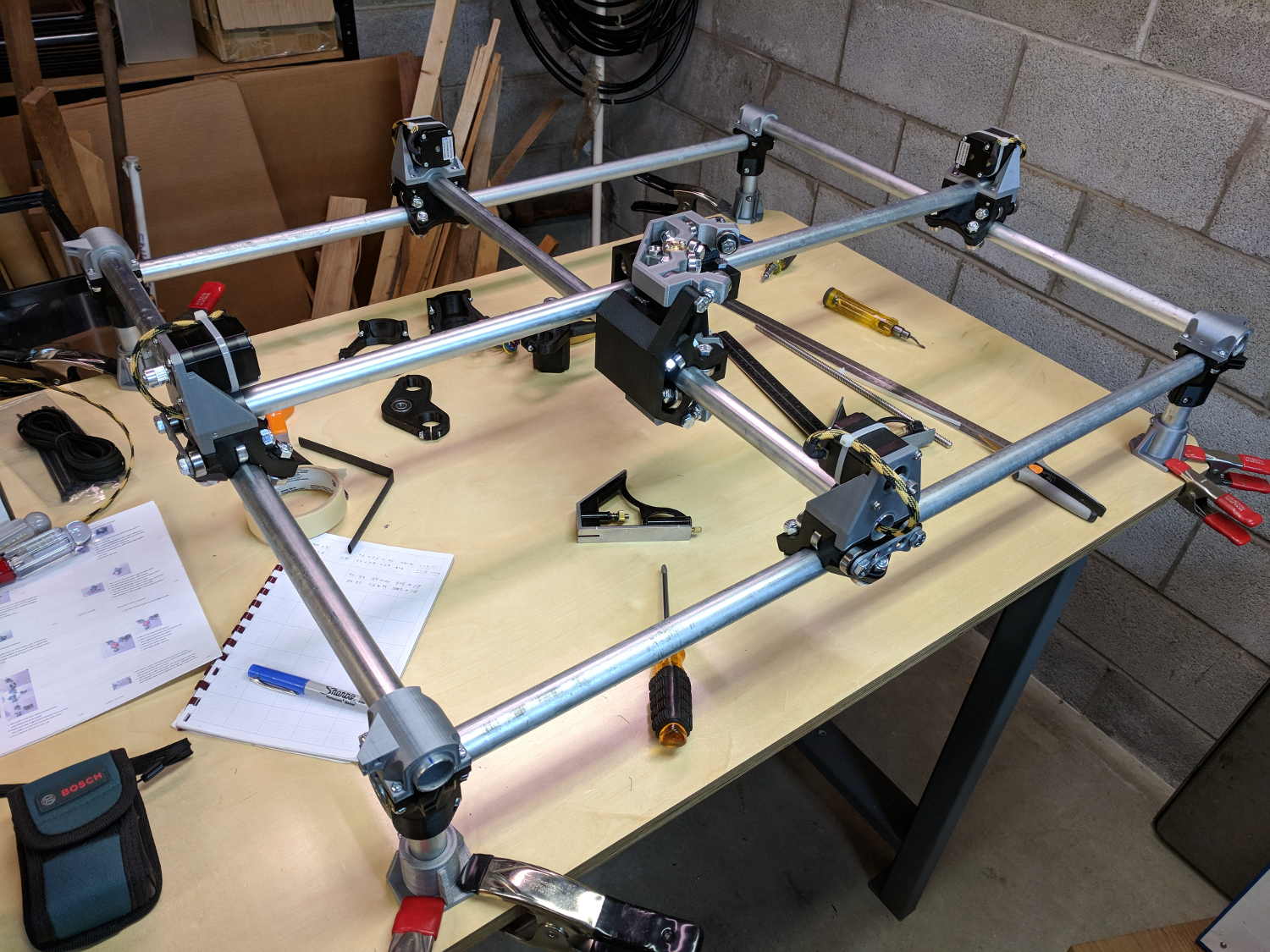
The first trial assembly atop a new workbench went reasonably smoothly:
Mostly Printed CNC – construction overview
I missed the step where you must put the high rails parallel to the X axis, which I want along the length of the table, and had to disassemble and rebuilt the frame to rotate the Middle Assembly a quarter turn clockwise. It’s always easier the second (or third) time and, if you regard the first few passes as dry runs / learning experiences, the process can be soothing, rather than annoying.
A laser rangefinder dramatically simplifies squaring and de-skewing the rails:
MPCNC – Laser rail measurement
I wanted 24+ inches along the X axis and 18+ inches along the Y, so as to handle stock sizes with hard-inch measurements.The current MPCNC design adds about 11 inches to each axis outside the work area, which makes the footprint 35 × 29 (-ish) inches overall. The bench measures 30 inches front-to-back, I allowed an inch along the front to recess the moving parts, and the final frame measures 37+ × 30+ inches to the outside of all the gadgetry.
Within that footprint, the laser says the rails are 845 × 674 mm = 33 × 26+ inch apart, giving a work area of 640 × 475 mm = 25+ × 19- inch.
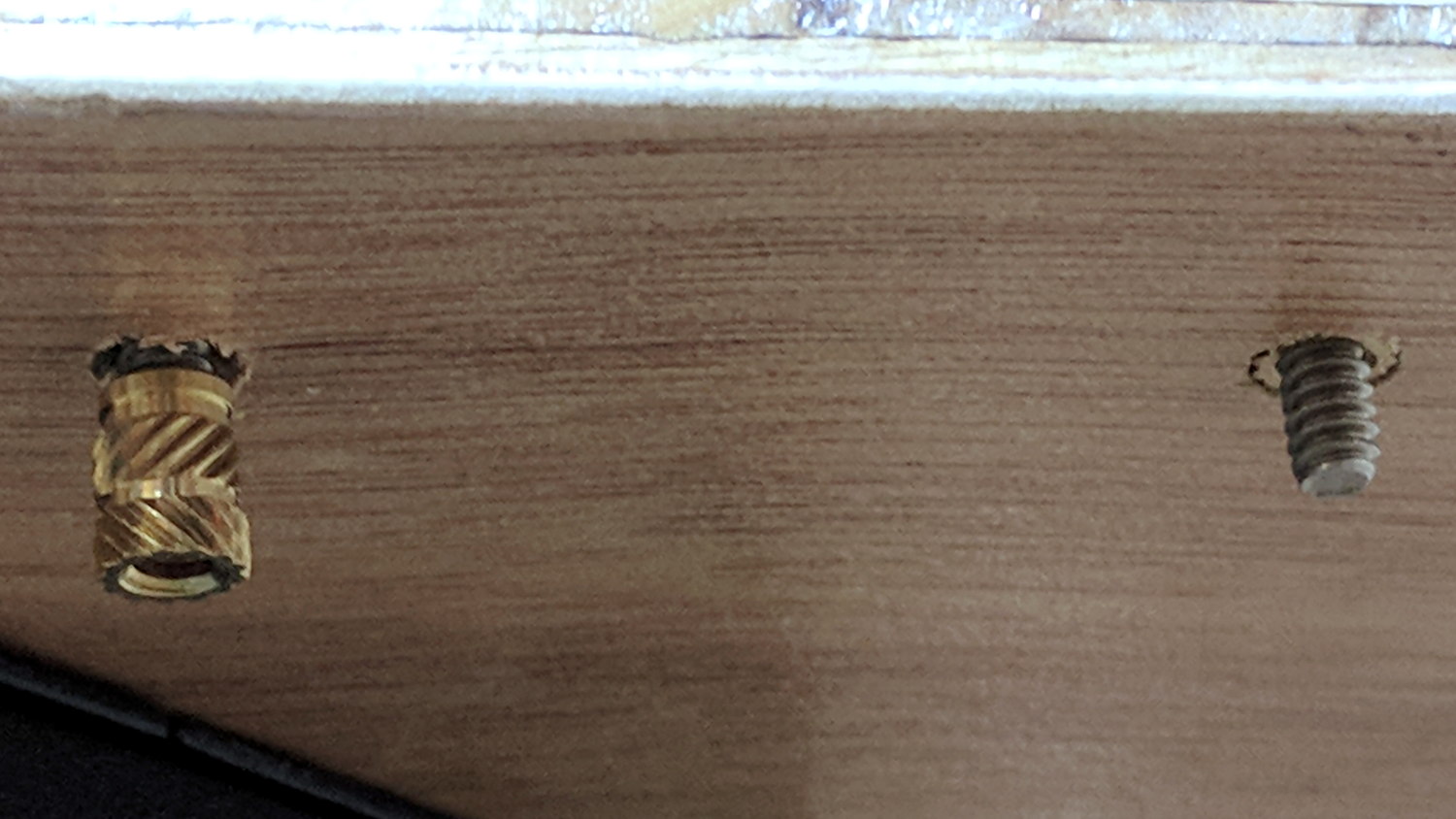
After some careful surveying, I marked / punched / drilled holes for each mounting foot, then counterdrilled brass inserts on the bottom for that nice clean look:
MPCNC – Table anchors
The screws came out flush when mounted atop washers:
MPCNC – Corner Assembly
My “careful surveying” produced a 1 mm error over the internal 1 meter diagonal, but a bit of judicious hole filing let me squash the long diagonal and stretch the short one by Just Enough to make the answer come out right, at least according to the laser rangefinder.
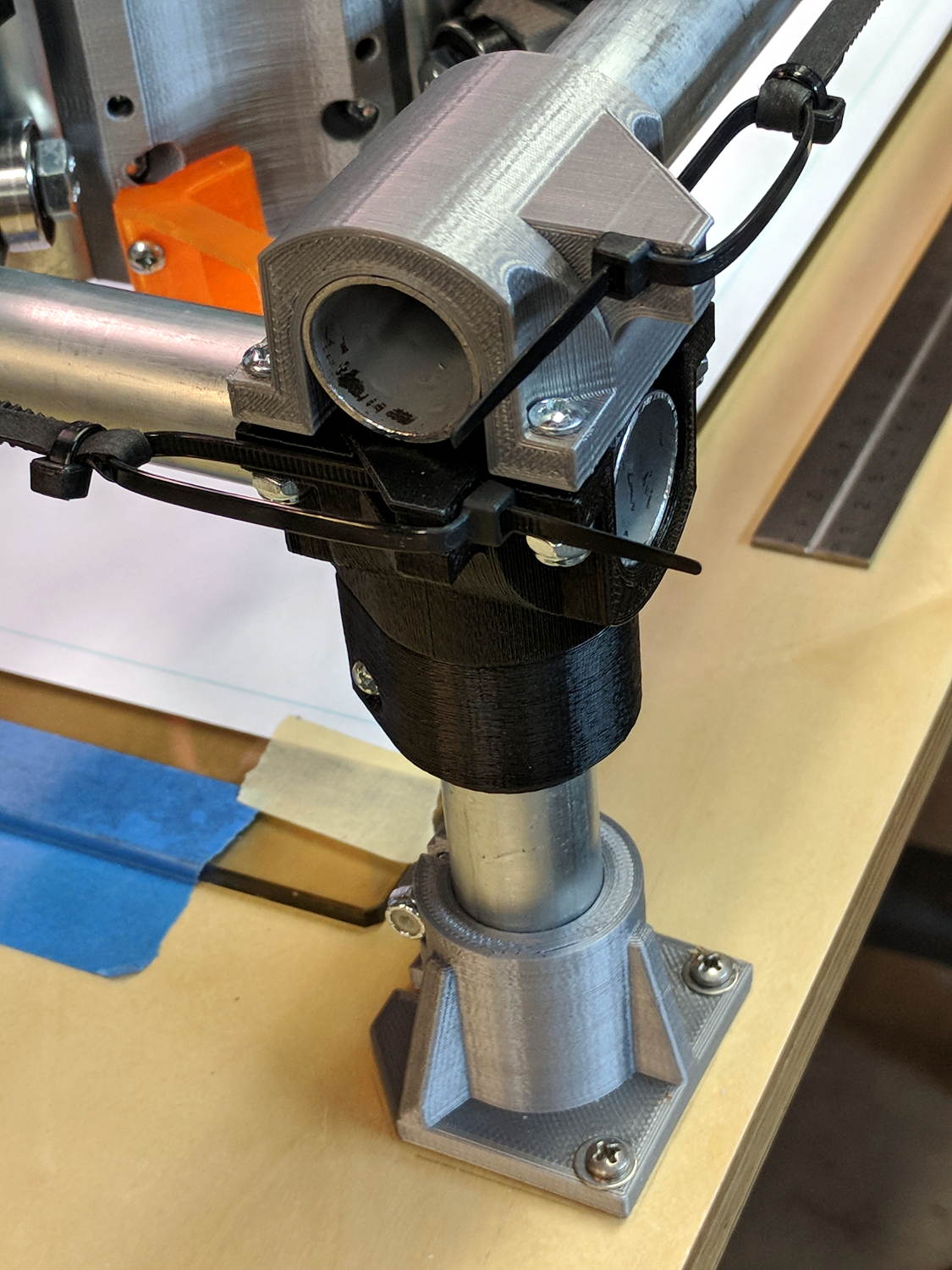
Setting the rail height goes more easily with a height gauge:
MPCNC – Rail height measurement
Stipulated: the absurdity of a height gauge on a plywood tabletop. On the other paw, the corner posts rest on that same plywood, so it actually works pretty well. I slowly pried the three lowest caps upward with the Big Screwdriver, levered on a wood block, to set all the rails to the same height as the highest one.
The X axis rails may need mid-rail supports, although I don’t see any meaningful deflection right now.
One could mount a T-nut atop the table inside each foot (and the center brace, as needed), with a long-ish bolt (head below the table) pushing the corner joint upward, which might be more stable than the current plastic-on-steel compression grip.
The steppers mount on rollers gripping the rail with six bearings, plus two more bending the GT2 drive belt (not installed yet) upward to the motor drive pulley:
MPCNC – Stepper on Roller
I devoted a few quiet hours to threading four-wire cables through 6 mm PET braided sleeves, in hope of protecting the PVC insulation from the usual abrasion & bending stresses. I have some drag chains which may come in handy, although they seem overly klunky for the purpose.
I’m not entirely convinced a PLA stepper mount is a Good Thing, given the warmth of steppers and PLA’s 60 °C glass transition temperature. We’ll see how it goes; obviously, one should not leave PLA parts in one’s car during a hot summer afternoon, either.
The neatly sheathed stepper cable vanishes into the center rail held firmly by the stepper mount. An identical stepper mount grips the other end of the rail, with the motors wired in series. The conduits provide a tidy way to pass wires along the length and width of the frame.
After you install and tension the belts, tweak the pulley location so the 6 mm belt tracks more-or-less in the middle of the 9 mm tooth width:
It has six printed parts, three each in two matching pairs, 24 bearings in eight triples, and plenty of 5/16 inch bolts + locknuts holding it together: all the metal bits make it weigh a lot more than you’d expect.
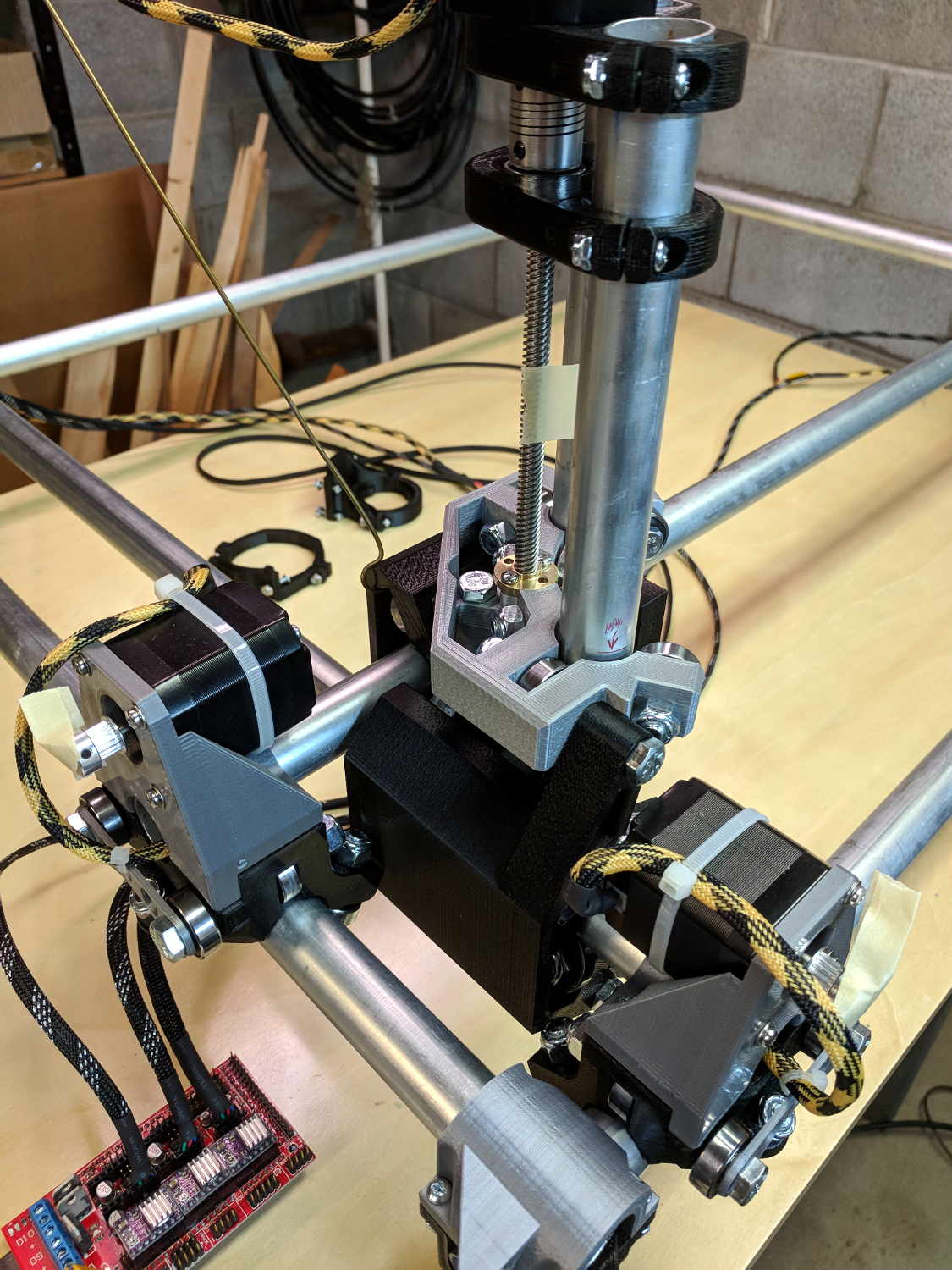
The Z axis rails fit into the two pairs of three bearings facing you:
MPCNC – Correct Mid-Assembly orientation
You’ll note the correct Middle Assembly orientation, after I rearranged the frame with the high rails along the X axis. Home switches will eventually fit neatly on the untraveled rail sections near the front-left corner post.
I built the Z using the default 12 inch rails called out by the Cut Calculator (metric version), which left an inch of the leadscrew sticking out beyond the bottom of the rails:
MPCNC – Z leadscrew – 12 inch rails
I left the work height at the default 4 inches, which specifies a minimum 7 inch = 175 mm leadscrew. The actual leadscrew is 300 mm = 8 inch, which completely explains the situation. I’ll rebuilt the Z axis with longer rails, but this suffices for now.
The concave silvery part joining the Z axis struts is the tool mount, to which you screw a tool holder:
MPCNC – Pen Holder Detail
That’s the Official Drag Knife / Pen Holder, generally seen with a Sharpie ziptied in place, but I have Real Plotter Pens, dammit, and I’m going to use them! The holder has one hole dangling to put the pen nib below the end of the leadscrew.
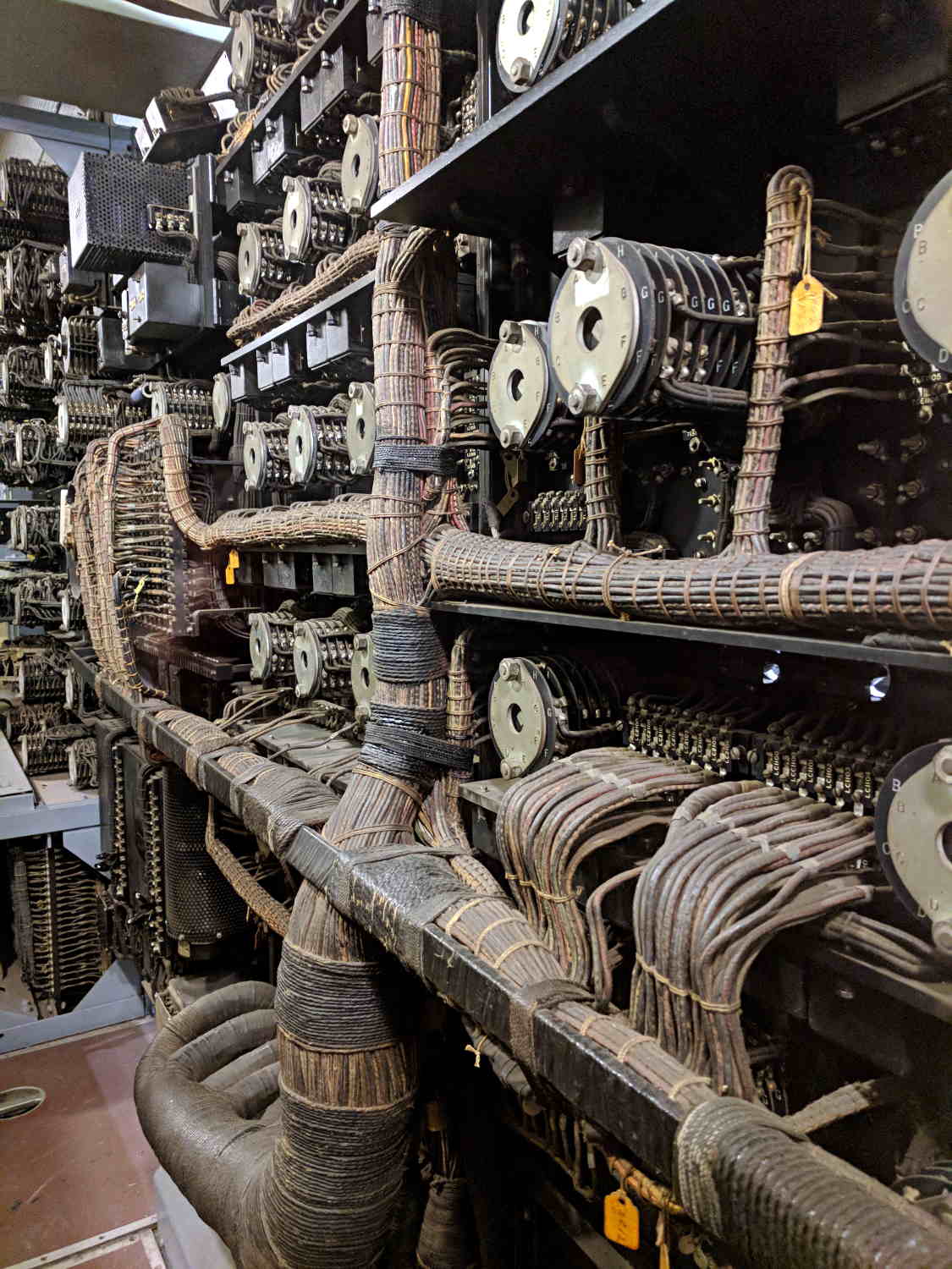
We explored the interior for several hours, all the way to the lower Turret 2 barbette:
USS Massachusetts BB-59 – Turret 2 Lower Barbette 16 inch Shell Storage
Each 16 inch projectile weighs 2700 pounds, with 800 shells distributed around three turrets. Looking at the drawings doesn’t make up for seeing the machinery.
The Massachusetts did shore bombardment during the Solomon Island campaign, where my father was assigned to guard a forward observer targeting Japanese redoubts and caves. He said the first rounds went over the far horizon, the second group landed short in the valley, and, from then on, the observer called out coordinates, walked the impact points down the valley, and wiped out each target in succession. BB-59 may not have been on the other end of those trajectories, but he said the Navy saved them plenty of trouble and inconvenience …
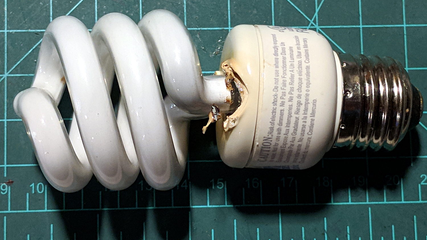
An overhead light in the Basement Laboratory went dark:
Failed CFL bulb
One end of the twisty tube got really really hot as it failed!
The Lab didn’t smell of electrical death, so the bulb must have failed while I was elsewhere. Metal enclosures with actual UL ratings suddenly seem like a Good Idea …
A reader (you know who you are!) proposed an interesting project that will involve measuring audio passbands and suggested using white noise to show the entire shape on a spectrum analyzer. He pointed me at the NOISE 1B Noise Generator based on a PIC microcontroller, which led to trying out the same idea on an Arduino.
The first pass used the low bit from the Arduino runtime’s built-in random() function:
Arduino random function bit timing
Well, that’s a tad pokey for audio: 54 μs/bit = 18.5 kHz. Turns out they use an algorithm based on multiplication and division to produce nice-looking numbers, but doing that to 32 bit quantities takes quite a while on an 8 bit microcontroller teleported from the mid 1990s.
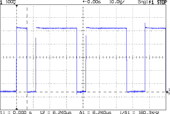
The general idea is to send a bit from the end of a linear feedback shift register to an output to produce arandomly switching binary signal. Because successive values involve only shifts and XORs, it should trundle along at a pretty good clip and, indeed, it does:
Arduino Galois shift reg bit timing
I used the Galois optimization, rather than a traditional LFSR, because I only need one random bit and don’t care about the actual sequence of values. In round numbers, it spits out bits an order of magnitude faster at 6 μs/bit = 160 kHz.
The spectrum looks pretty good, particularly if you’re only interested in the audio range way over on the left side:
Arduino Galois bit spectrum
It’s down 3 dB at 76 kHz, about half the 160 kHz bit flipping pace.
If you were fussy, you’d turn off the 1 ms timer interrupt to remove a slight jitter in the output.
It’s built with an old Arduino Pro Mini wired up to a counterfeit FTDI USB converter. Maybe this is the best thing I can do with it: put it in a box with a few audio filters for various noise colors and be done with it.
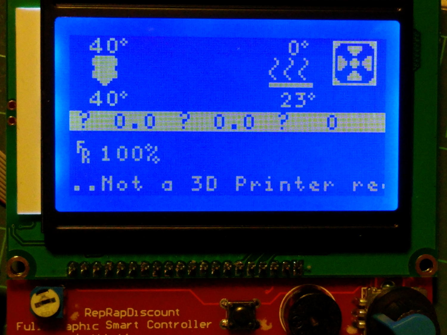
It occurs to me I could fire it into the 60 kHz preamp’s snout to measure the response over a fairly broad range while I’m waiting for better RF reception across the continent.
This file contains hidden or bidirectional Unicode text that may be interpreted or compiled differently than what appears below. To review, open the file in an editor that reveals hidden Unicode characters.
Learn more about bidirectional Unicode characters
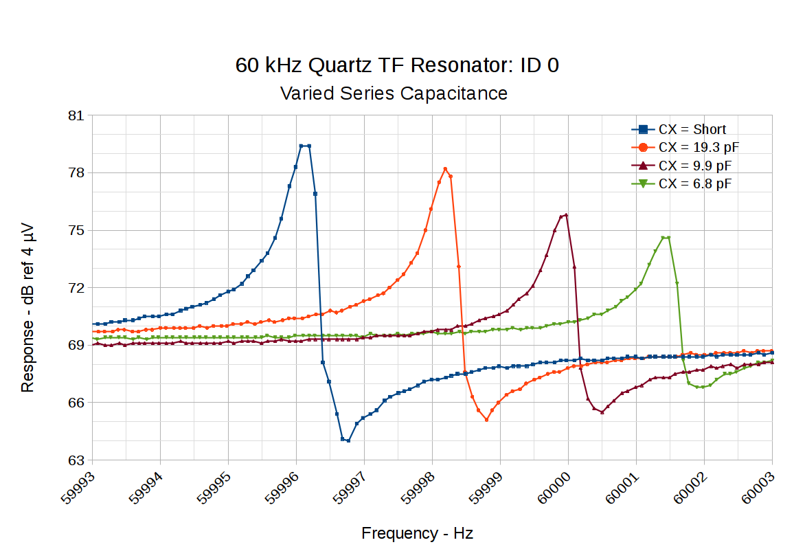
Putting a small capacitor in series with the tuning fork resonator pulls the series resonant frequency upward and reduces the amplitude:
60 kHz Quartz TF Resonator – CX variations
So something around 10 pF, net of stray capacitance and suchlike, should suffice. Plunk a small twiddlecap on the preamp board and tune for best picture: