Ed Nisley's Blog: Shop notes, electronics, firmware, machinery, 3D printing, laser cuttery, and curiosities. Contents: 100% human thinking, 0% AI slop.
The longer traces show their original capacity, back in the day.
Whacking a chisel into the obvious split lines broke the solvent glue bonds holding the case sections together, after which some slow prying defeated the double sticky foam tape on the cells:
Baofeng BL-5 battery pack – innards
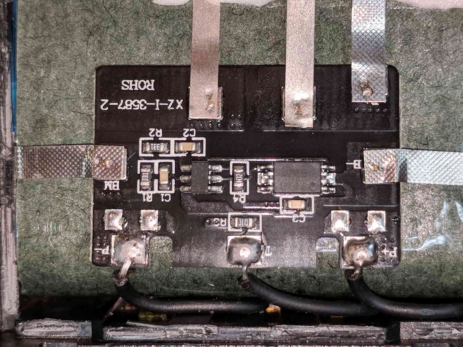
A closer look at the (dis)charge controller PCB:
Baofeng BL-5 battery pack – protection PCB
The other side of the PCB has no components, so what you see is what you get. The larger IC proclaims FS8205A EP050C, which may indicate a vague relation to an S8205 protection IC. The datasheet shows a 16 pin TSSOP package containing an IC for four or five cell batteries, completely unlike the 8 pin package on the PCB, but when you buy enough of anything, you can get anything you want.
In common with all cheap lithium batteries around here, the “thermistor” terminal connects to a 10 kΩ SMD resistor steadfastly maintaining its resistance in the face of all temperature variations.
Some probing shows one feeble cell in each pack. Perhaps a Frankenbattery built from the debris will have enough capacity for a standard ride around the block.
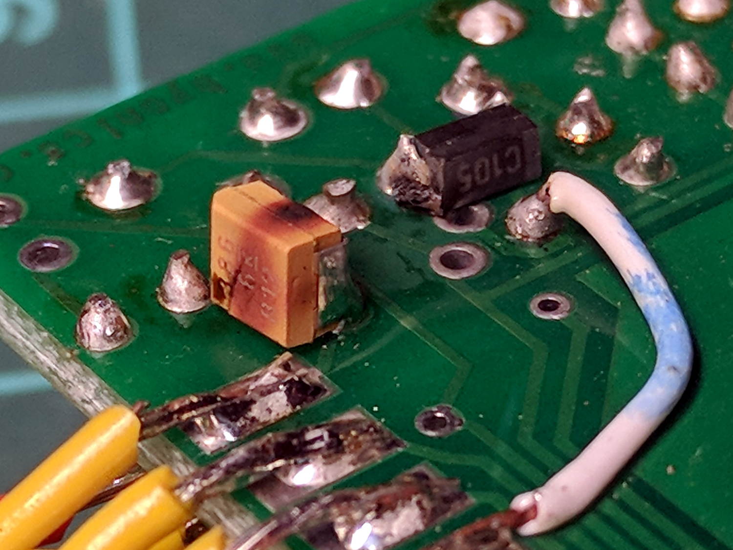
The TinyTrak3 on the Wouxun adapter wasn’t working, showing a dim red Power LED to indicate it wasn’t getting enough juice. A bit of tracing showed my adapter board provided just over 5 V to the poor thing, not the nearly 9 V it should be getting, which led me to believe the transistor switching the supply had failed. A bit more tracing, however, revealed the true problem:
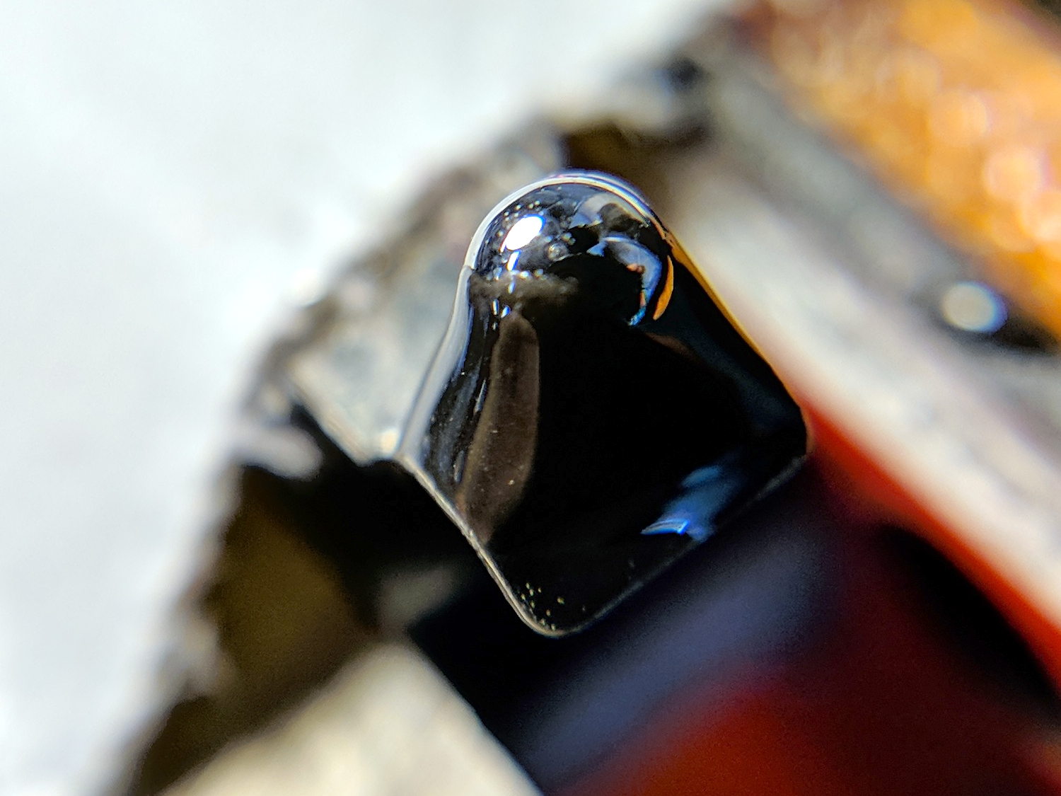
Failed electrolytic cap
The schmutz on the black cap matches up with a crater in the rear of the (originally not so) brown cap.
The Little Box o’ SMD Caps revealed two nearly identical sets of 33 μF caps, one with a 6 V rating, the other with 16 V rating. Yup, when I added that cap in the hopes of reducing RFI troubles, I soldered the wrong one onto the PCB: it’s my fault!
The poor thing lasted for over six years with just under 9 V applied to it, so I can’t complain.
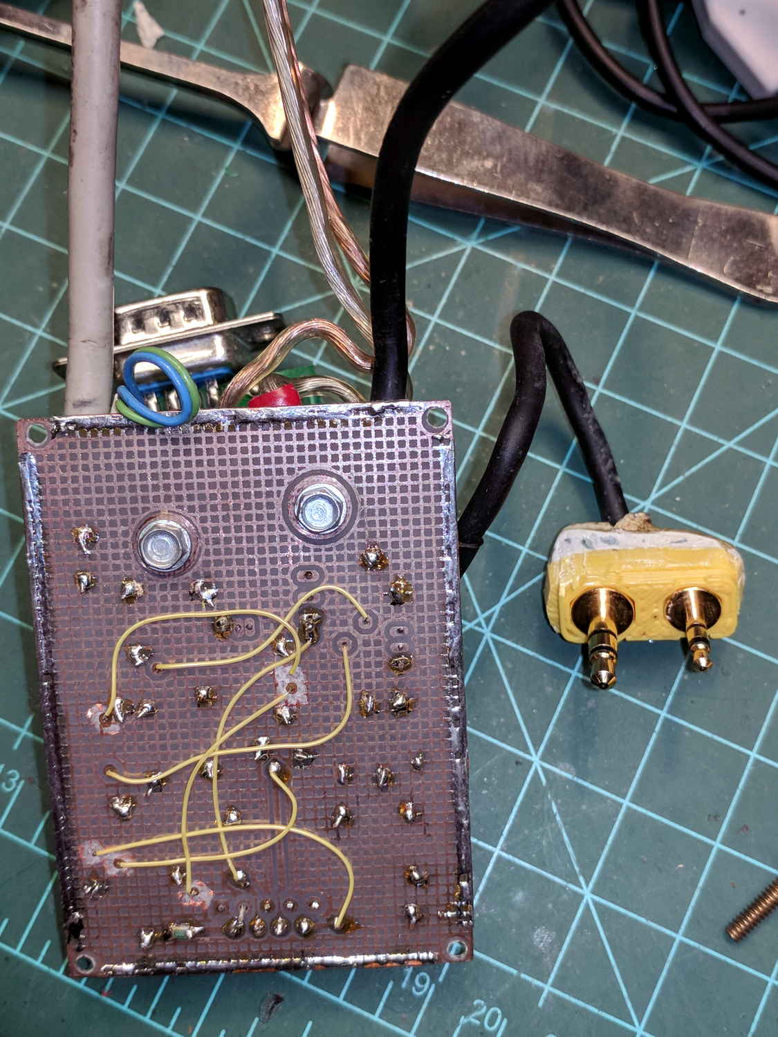
I removed the corpse and reassembled the box without the additional cap (and without the terminals contacting the back of the Wouxun, because reasons). If RFI turns out to be a problem, I’ll take another look at the situation.
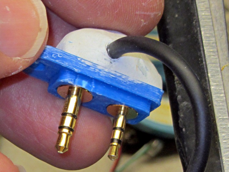
… of course don’t fit the Baofeng radio. This being in the nature of a final fix, I chopped off enough protrusions to make the remainder fit snugly into the recess.
Based on one ride, both Baofeng batteries have very little capacity left after several years on the shelf, which comes as absolutely no surprise whatsoever.
The pavement along Rt 376 between markers 1111 and 1108 has deteriorated into deep chasms, potholes, and fissures.
The linear disintegration south of marker 1111 seems to follow an underlying concrete joint. The shoulder has deep, tire-trapping fissures, forcing cyclists far out into the travel lane along a narrow and curved part of Rt 376:
Rt 376 SB deterioration – S of marker 1111 – 2018-02-20
The hole at address 2181 (across from Paula’s House / GastroPub) was previously patched, but recent weather has excavated it nearly a foot deep. The shoulder has also deteriorated, again forcing cyclists into the travel lane:
Rt 376 SB deterioration – at 2181 driveway – 2018-02-20
The previous patches along the inside of the curve just north of Heathbrook Drive (south of marker 1108) have disintegrated. There’s no shoulder at all along that section and the fissures in the travel lane force cyclists into the lane along a blind curve:
Rt 376 NB deterioration – S of marker 1108 – 2018-02-20
This section of NYS Bicycle Route 9 poses an immediate danger to both cyclists and motorists, so I reported all these to NYS DOT and, a day later, a crew traveled along Rt 376 shoveling cold patch into many of the holes and flattening the lumps more-or-less parallel to the road surface: it’s now driveable, if still a hazard for bicycle traffic.
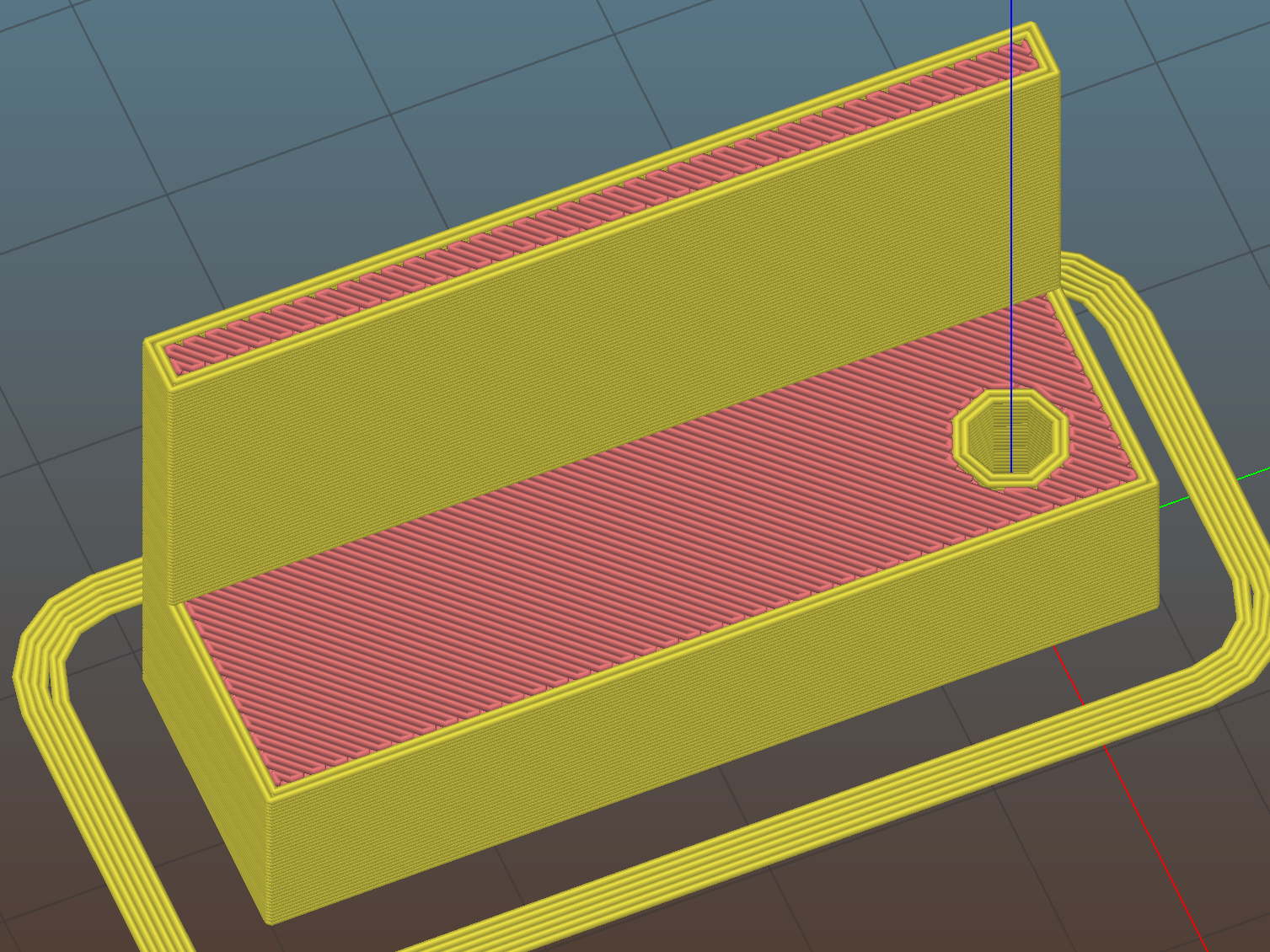
The DW660 collet grabs a length of 1/8 inch drill rod jammed into a hole positioned to put the switch actuator directly in line with the spindle axis when it trips the switch, so as to measure a known and useful location:
Z Axis Height Probe – MBI endstop – Slic3r
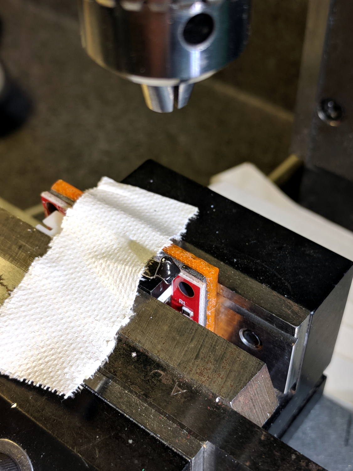
After mulling things over for a while, I fired up the Sherline, drilled a #54 hole in the actuator, and epoxied a 3/32 inch bearing ball in the hole:
MPCNC – Endstop Z probe – bearing
A #54 drill hole is half the diameter of the ball and, with a bit of luck, enough of the ball will stick through into the epoxy on the underside for a good grip:
MPCNC – Endstop Z probe – bearing – detail
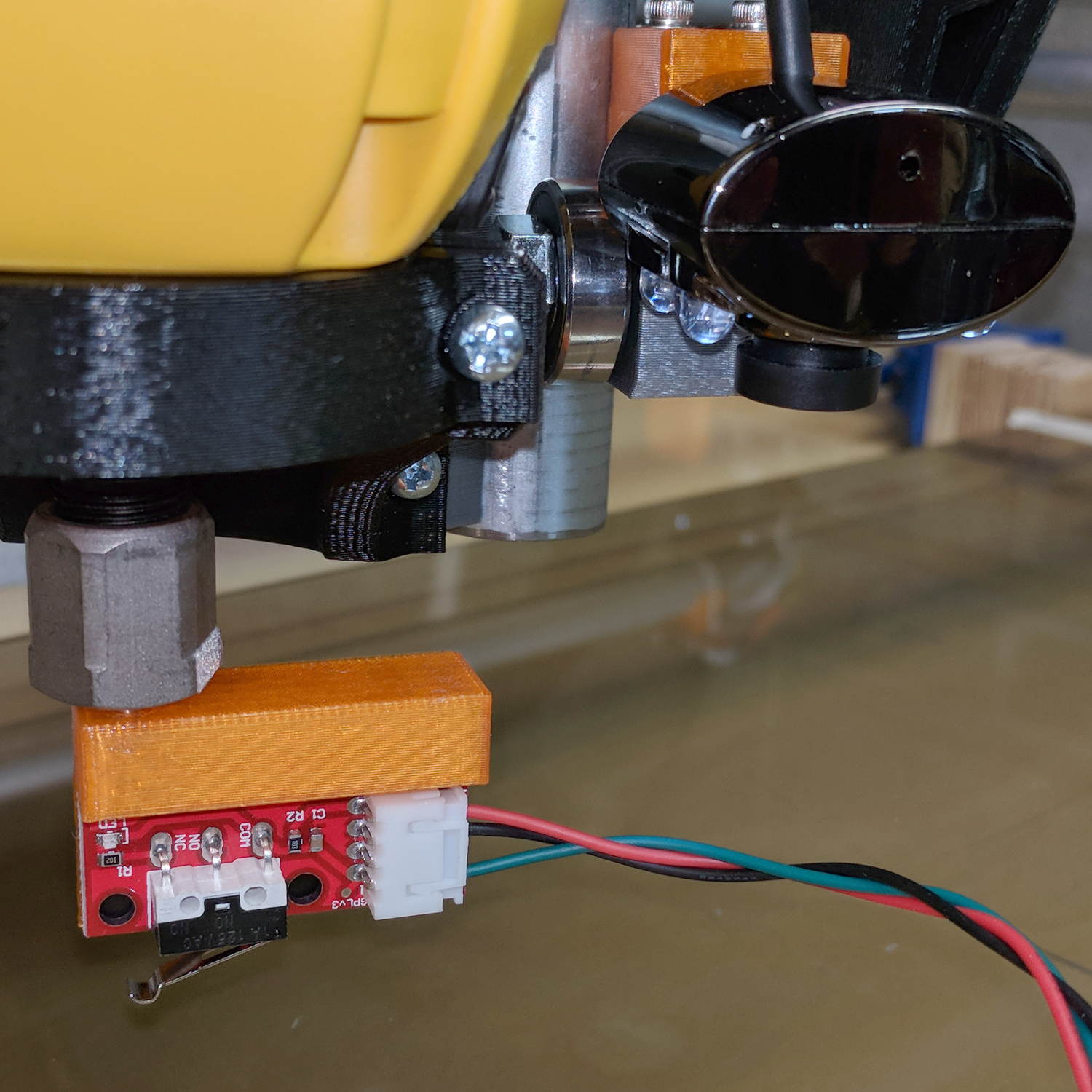
The general idea is to convert the stamped steel actuator into a single, albeit not particularly sharp, contact point that can glide over the platform / PCB / sheet-of-whatever to measure the surface. The actuator pivots as it depresses, so the ball must slide horizontally just a bit. I prefer a rod-in-tube probe poking a linear button switch, but those weren’t getting me anywhere.
This file contains hidden or bidirectional Unicode text that may be interpreted or compiled differently than what appears below. To review, open the file in an editor that reveals hidden Unicode characters.
Learn more about bidirectional Unicode characters
I have often asserted, in public, in writing, that you can’t change the speed of a fan’s BLDC motor by varying its voltage, because the fan controller generates the waveforms responsible for the motor speed based on its internal timing.
A pair of BLDC blowers recently arrived and a quick test showed I’m pretty much completely wrong:
BLDC Blower – RPM I P vs V
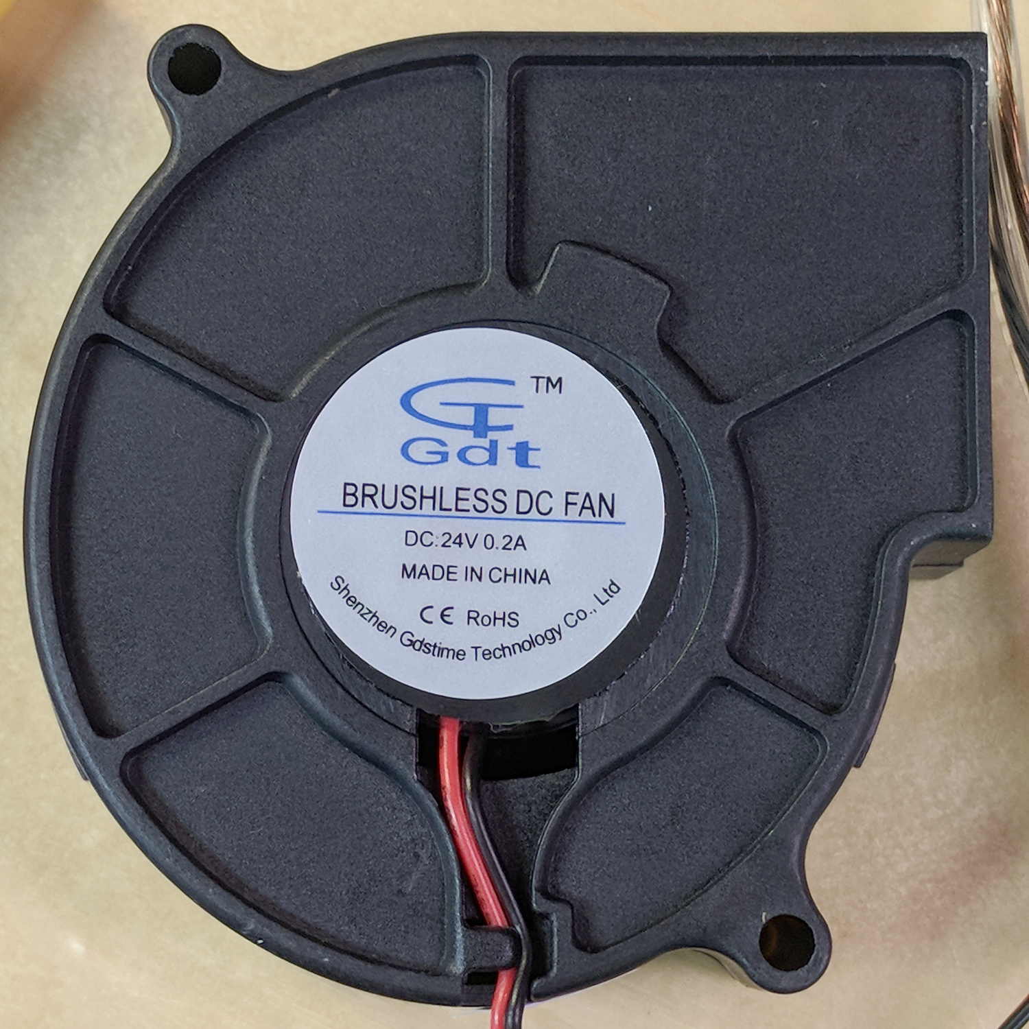
The data points come from this blower:
Blower label – 24V 0.2A
The blower specs from the eBay listing:
75MM 24V Brushless DC Blower Cooling Fan Exhaust Fan
Dimension:75(L)x75(W)x30(H)mm
Connector:2Pin-PH2.0
Rated Voltage: DC24V
Rated Current: 0.2±10% Amp
Rated Speed: 3800±10%rpm
Air flow:1.8CFM
Noise: 23±10%dBA
Bearing Type: Sleeve
Life: 35000 hours
Cable Lenght: 32cm(12.5in)
Weight: 75g/pcs
The case is about 75 mm × 75 mm × 30 mm, so the generic part number seems to be 7530, with many variations. However, they all seem to resolve to the same blower with different models drawing different current at specific voltages (clicky for more dots, JPG blurriness in original):
GDT7530S12B BLDC blower parameter table
The blower in hand roughly corresponds to the bottom line of the 24 V section:
0.21 A
4000 RPM
16.3 CFM
1.1 inch H2O pressure
43 dBA
There’s a gross discrepancy between the eBay 1.8 CFM and the chart 16.3 CFM, but the other parameters seem within handwaving distance and, yo, it’s from eBay. ‘Nuff said.
The graph up top shows the results with an unrestricted output opening.
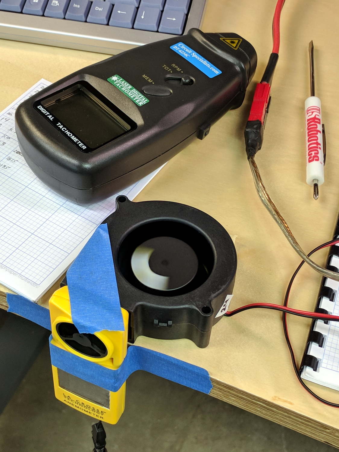
For more realistic results with some resistance to air flow, I taped a small anemometer to the blower output:
Blower air flow test
Which produced:
BLDC Blower – RPM Flow vs V – anemometer
In very round numbers, the anemometer aperture is 400 mm², so the 9 m/s air flow at 24 V works out to 3.6×10⁻³ m3/s = 0.13 CFS = 7.6 CFM. Which is maybe half the 16.3 CFM spec, but they’re surely using a fancier anemometer with much lower back pressure. Close enough, anyway. Fer shure, 1.8 CFM is wrong.
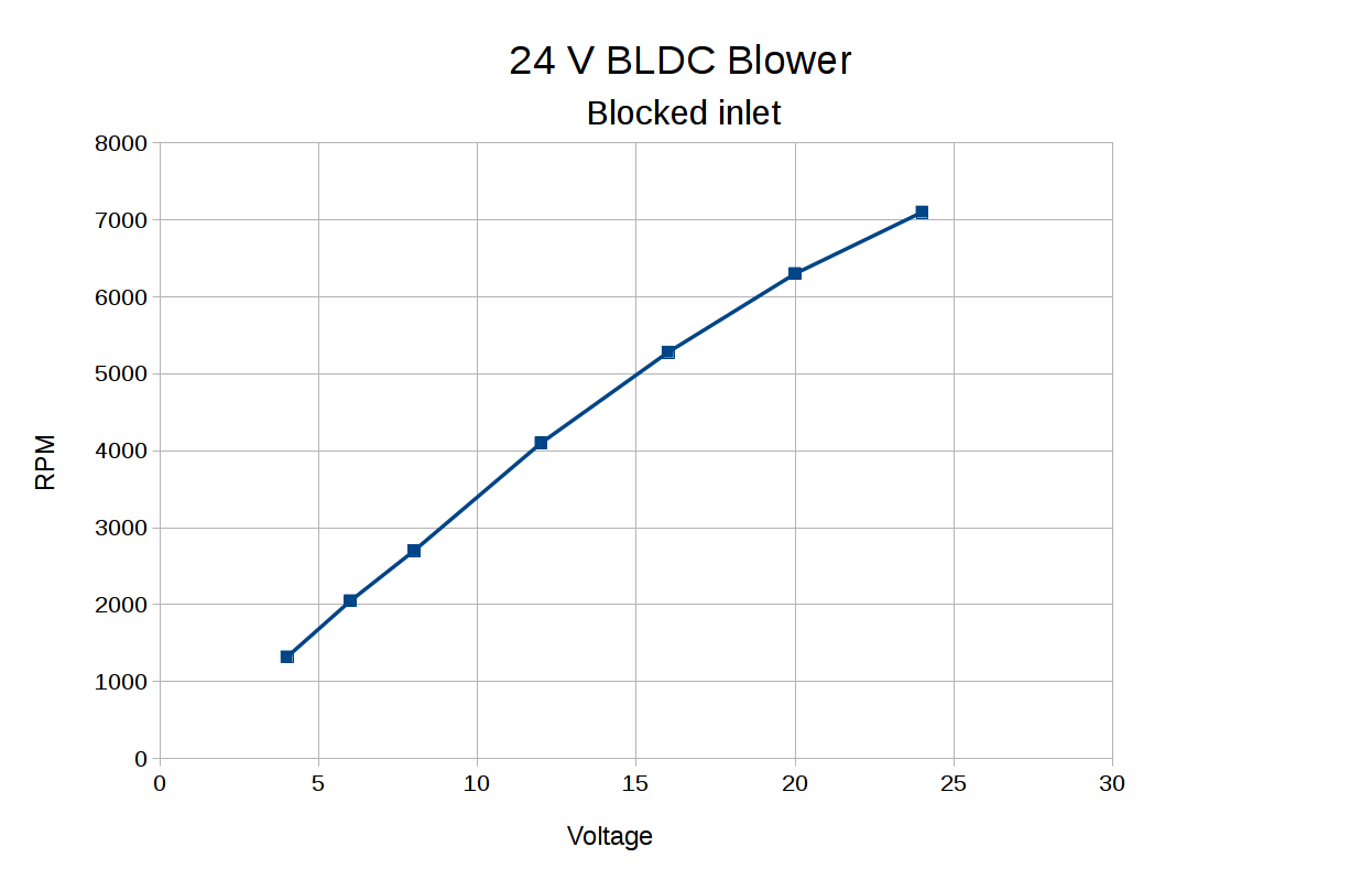
Completely blocking the inlet with a plastic sheet to simulate the blower pulling air from, e.g., a vacuum table:
BLDC Blower – RPM vs V – blocked inlet
The RPM varies more linearly with voltage when the blower isn’t accelerating any air.
Some current waveform show why you really shouldn’t run fans in series to “split the power supply”, as seems common in 3D printers with 24 VDC power supplies.
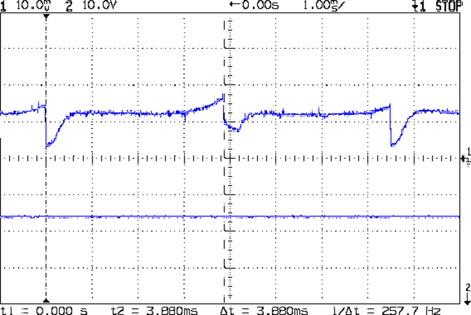
From a 24 V supply, the current drops to 50 mA every 75 ms (200 mA/div):
BLDC 24V Blower – 24 V – 200mA-div
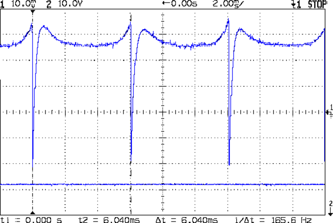
From a 12 V supply, even weirder things happen (50 mA/div):
BLDC 24V Blower – 12 V – 50mA-div
Note that you can’t reduce the fan’s supply voltage by applying PWM to the current, as happens in essentially all 3D printers for “speed control”. Basically, PWM turns the fan off several hundred times every second, which does not modulate the voltage.
I have no way to measure pressure, but if the 1.1 inch H2O number comes close to reality, the blower can produce 1.5 lb of clamping force per square foot. Which isn’t a lot, granted, but it might suffice for paper and vinyl cutting.