Ed Nisley's Blog: Shop notes, electronics, firmware, machinery, 3D printing, laser cuttery, and curiosities. Contents: 100% human thinking, 0% AI slop.
For unknown reasons, the Gnome-ish vino-server package for Xubuntu 18.04 no longer installs vino-preferences, so it’s not obvious how to configure the server.
After considerable flailing, I installed good old x11vnc, set up a password, then started it in .xprofile:
x11vnc -forever -find -no6 -avahi -usepw
I don’t mind having programs change, but it’d be nice if features like, say, configuration wouldn’t just vanish.
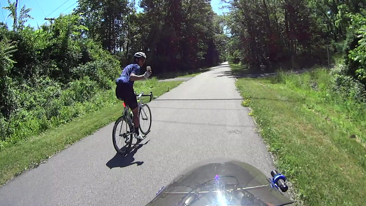
On the Dutchess Rail Trail, just north of Page Industrial Park:
Biggest Clown in the Parade – Photo Op – 2018-06-17
Ya gotta admire the confidence of anyone manipulating a kilobuck of slippery glass while looking backward over his shoulder. I’ll take a helmet camera any day, if only because it’s really conspicuous.
He’s leading a group of four riders, all on spendy carbon-fiber bikes:
Biggest Clown in the Parade – Peloton – 2018-06-17
Presumably they’re all smiling at the sight of a recumbent towing a trailer of garden tools topped with two bags of just-picked lettuce. I’m definitely the biggest clown in this particular parade!
We’re ticking along at 18 mph and, as it turned out, drafting a quintet of upright bikes is surprisingly easy. If I weren’t towing the trailer with Mary just out of sight ahead, I’d have had some fun until they decided they’d had enough.
It’s good to bring such happiness into the world …
This is just after noon, when deer should be snoozing, north of Paula’s Public House, with the deer on the creek side of the road. I’m towing the trailer with an empty propane tank, coasting down from 18 mph, and expecting the deer to jump in front of me, because that’s what deer do. It waited patiently until I passed, hopped the guide rail, trotted across the road, then clambered up the steep hillside away from the Mighty Wappinger Creek.
Searching for deer will reveal many more encounters.
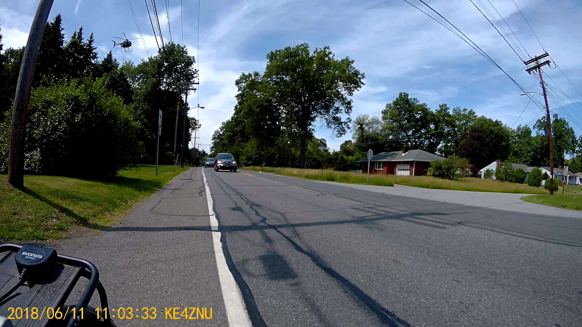
We heard God’s Own Weedwhacker off to the right as we approached Jackson Drive on the way home:
Chopper over power lines – Vassar Rd near Jackson Dr – 2018-06-11
The chopper followed the power lines, just over the treetops, with the downdraft thrashing the leaves:
Chopper over power lines – Vassar Rd near Jackson Dr – rear camera – 2018-06-11
Long ago, I attended a talk about using choppers for power line inspection and maintenance. Apparently, someone with nerves of ice can replace insulator supports and aeolian dampers on high-tension lines while perched on a chopper hovering very very close to the conductors. Pilots with experience getting troops into and out of hot LZs are in high demand.
I’m sure they give the E911 call center a heads-up before taking off …
Ex post facto notes from the third Squidwrench Electronics Workshop.
Exhibit various 50 Ω resistors, including my all-time favorite, a 600 W 3 GHz dummy load:
600 W Dummy Load Resistor
… down to a 1/8 Ω metal film resistor.
The dummy load’s N connector triggered a regrettable digression into RF, belatedly squelched because I wasn’t prepared to extemporize on AC concepts like reactance which we haven’t covered yet.
Discussion of resistor applications, power handling, power derating with temperature, etc:
Whiteboard – Session 3 – Resistor power derating
Why you generally won’t find 50 Ω load resistors in Raspberry Pi circuits. Cartridge heaters for 3D printers, not aluminum power resistors, although everyone agrees they look great:
Power resistors on heat spreader
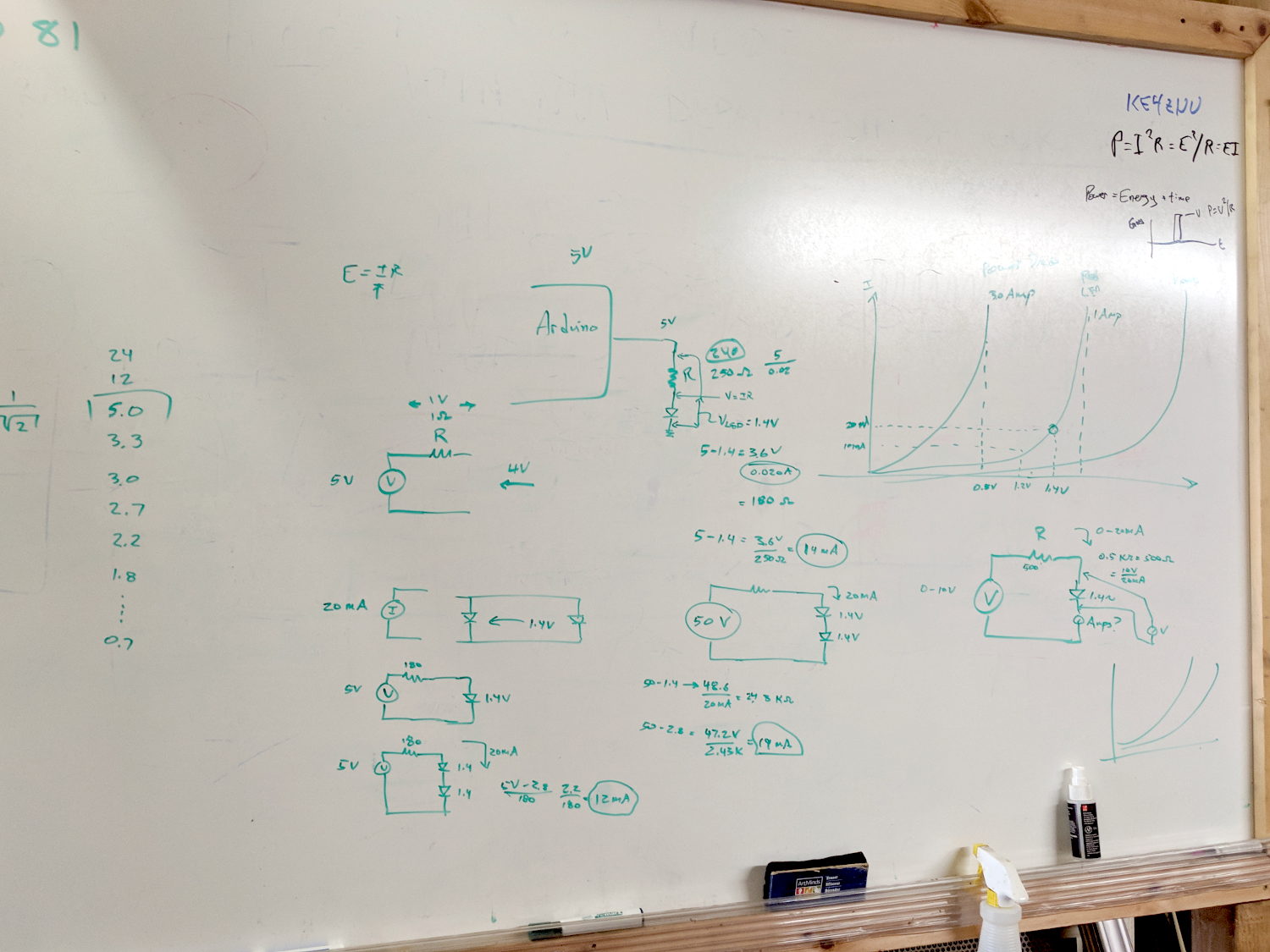
Discussion of voltage vs. current sources, why voltage sources want low internal resistances and current sources want high resistances. Bungled discussion of current sources by putting diodes in parallel; they should go in series to show how added voltage doesn’t change current (much!) in sources driven from higher voltages through higher resistances:
Whiteboard – Session 3 – Voltage vs Current Sources
Use Siglent SDM3045X DMM in diode test mode to measure forward drop of power / signal / colored LEDs, discuss voltage variation with color / photon energy. Measure 1.000 mA test current for all forward voltages.
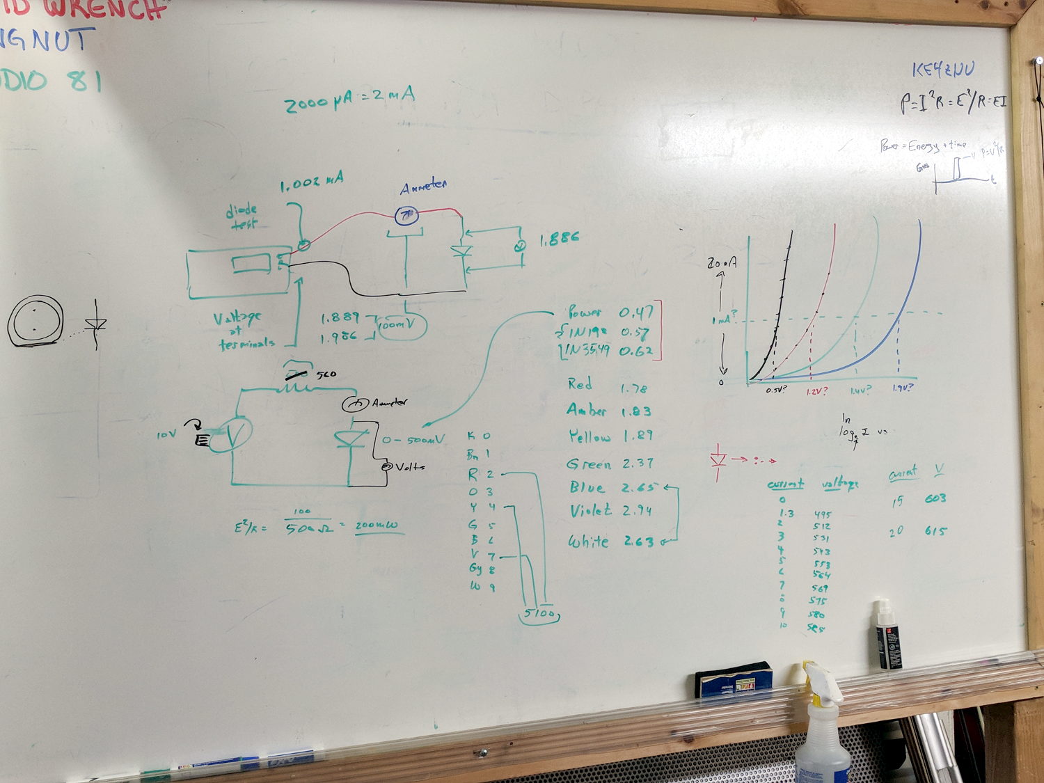
Compute series resistor (500 Ω) to convert adjustable power supply (the digital tattoo box, a lesson in itself) into reasonable current source; roughly 10 V → 20 mA. Find suitable resistor (560 Ω) in SqWr junk box parts assortment, digression into color band reading.
Wire circuit with meters to measure diode current (series!) and voltage (parallel!), measure same hulking power diode (after discovering insulating washers now in full effect) as before in 1 mA steps to 10 mA, then 15 and 20 mA, tabulate & plot results:
Whiteboard – Session 3 – Diode current vs forward drop
Discover warm resistor, compute power at 20 mA, introduce cautionary tales.
Lesson learned about never returning parts to inventory, with 560 Ω resistor appearing in diode drawer. Cautionary tales about having benchtop can of used parts as front-end cache for inventory backing store.
When I rewired the guts of the digital tattoo power supply to eliminate the series foot switch, I kept the original wiring polarity, with the black wire to the sleeve and the red wire to the tip:
Tattoo Digital Power Supply – internal view
It’s the same color code I (strongly) recommend in the Squidwrench Electronics Workshops: use any color for the ground / common wire as long as it’s black, then, if you have a red wire, use it for the positive supply. You can use yellow for the higher supply voltage, but stop being clever.
I put suitably colored Powerpoles on the far end of the cable to replace the standard tattoo machine spring clip connector, so I can attach clip leads, battery test fixtures, and so forth and so on.
We wired the supply into a clip-leaded diode measurement setup with a current limiting resistor and a pair of multimeters to measure the diode current and forward voltage, whereupon we noticed all the meters displayed negative voltages and currents.
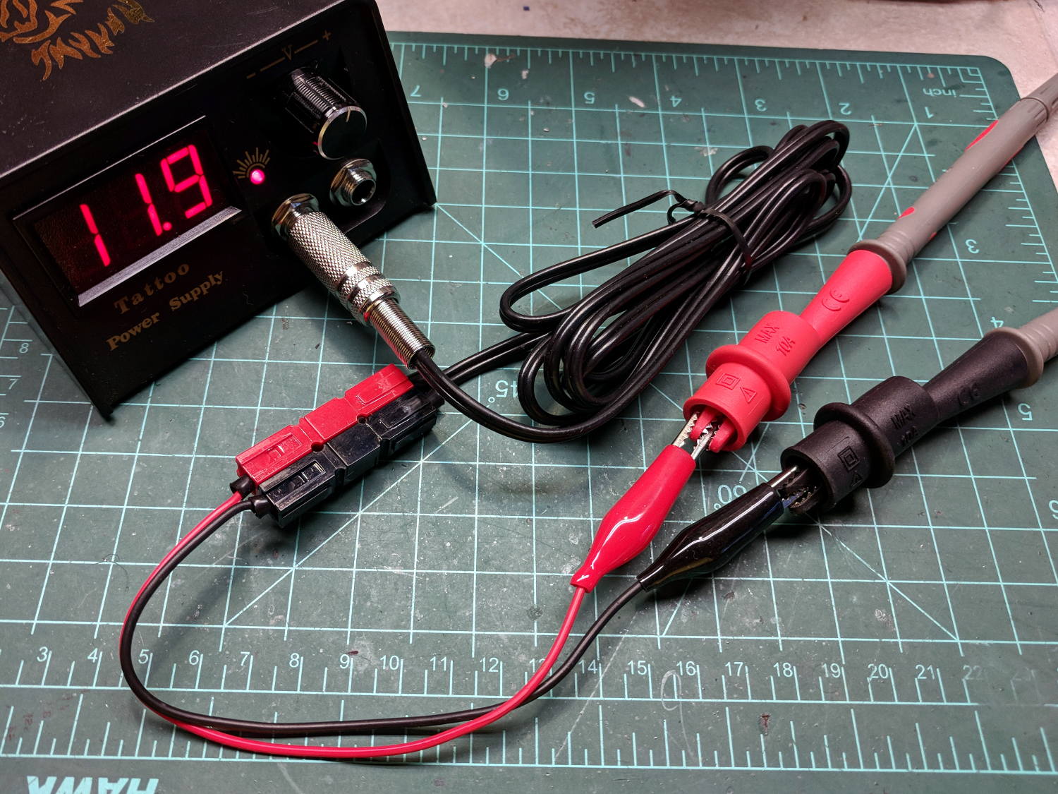
After a frenzy of wire-checking verified their setup was all good, I forced the simplest possible test, herein recreated on my bench:
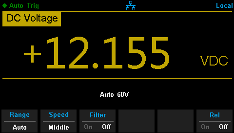
Tattoo Digital Power Supply – polarity test
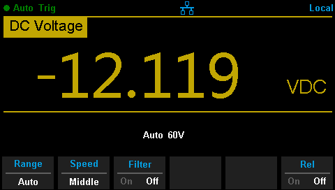
Which produced this display:
Tattoo Digital Supply – reverse polarity
Huh.
After a brief exploration of “Trust, but verify” territory, we swapped the clip leads from the power supply and continued the mission.
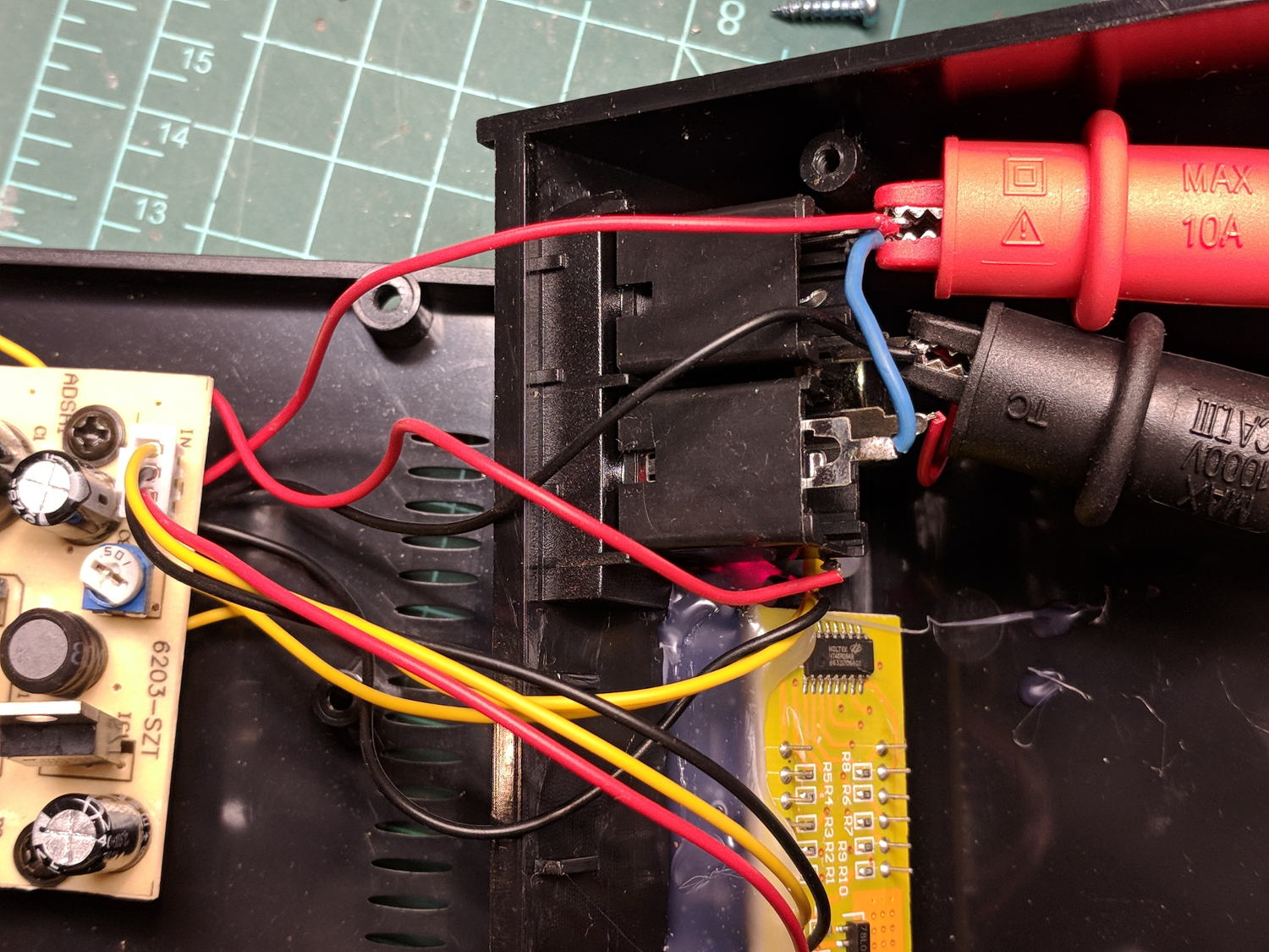
Back on my bench, I pulled the supply apart and measured the voltage at the jack terminals:
Tattoo Digital Power Supply – jack wiring
Still negative. Huh.
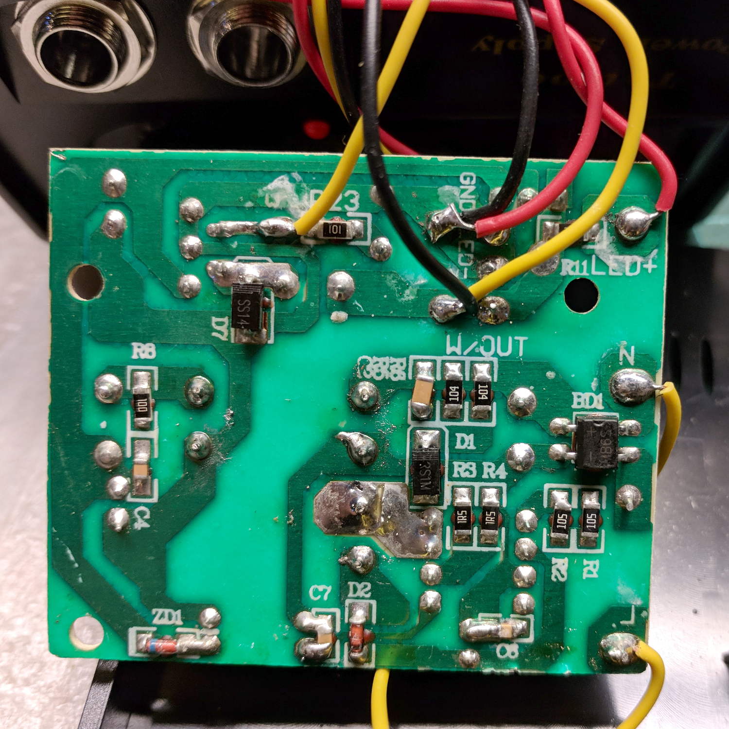
The bottom of the power supply PCB shows exactly what you should expect by now:
Tattoo Digital Power Supply – reversed color code
The red wire near the top of the board is, indeed, soldered to the trace labeled GND and goes to the jack’s tip terminal; the adjacent black wire goes to the front-panel LED. Similarly, the black wire just below it, soldered to the same trace as the yellow wire, goes to the jack’s sleeve terminal; that trace also connects to a resistor leading to the trace labeled LED+ and the LED’s red wire.
Although tattoo machines run from DC supplies, their motors or vibrators don’t depend on any particular polarity and will run fine with a backwards supply.
Resoldering the red and black wires where they should go produces the expected sign at the jack:
Tattoo Digital Supply – meter leads
Although measuring and plotting diode voltages and currents may seem tedious, actually wiring stuff together and taking data reveals how difficult the real world can be.
I trusted the supply’s internal color code and, although I’m certain I tested the Powerpoles, I obviously didn’t notice the meter’s sign.