Ed Nisley's Blog: Shop notes, electronics, firmware, machinery, 3D printing, laser cuttery, and curiosities. Contents: 100% human thinking, 0% AI slop.
Under normal circumstances, you’d use something like steel or lead sheets, but Tiny Bandsaw™ can’t cut any appreciable thickness of steel and I gave away my entire lead stockpile, so I sawed disks from a pile of non-stick pancake griddles and drilled suitable mounting holes:
Parallel clamps in action
Another disk (from a formal aluminum sheet!) goes into the lamp head, with a trio of 3W COB LEDs epoxied in place:
Ex-Halogen Desk Lamp – 3x3W COB LED assembly
The other side of the disk sports a heatsink harvested from a PC, also epoxied in place:
Ex-halogen Desk Lamp – heatsink fitting
Realizing the head required only a little filing to accommodate the heatsink sealed both their fates.
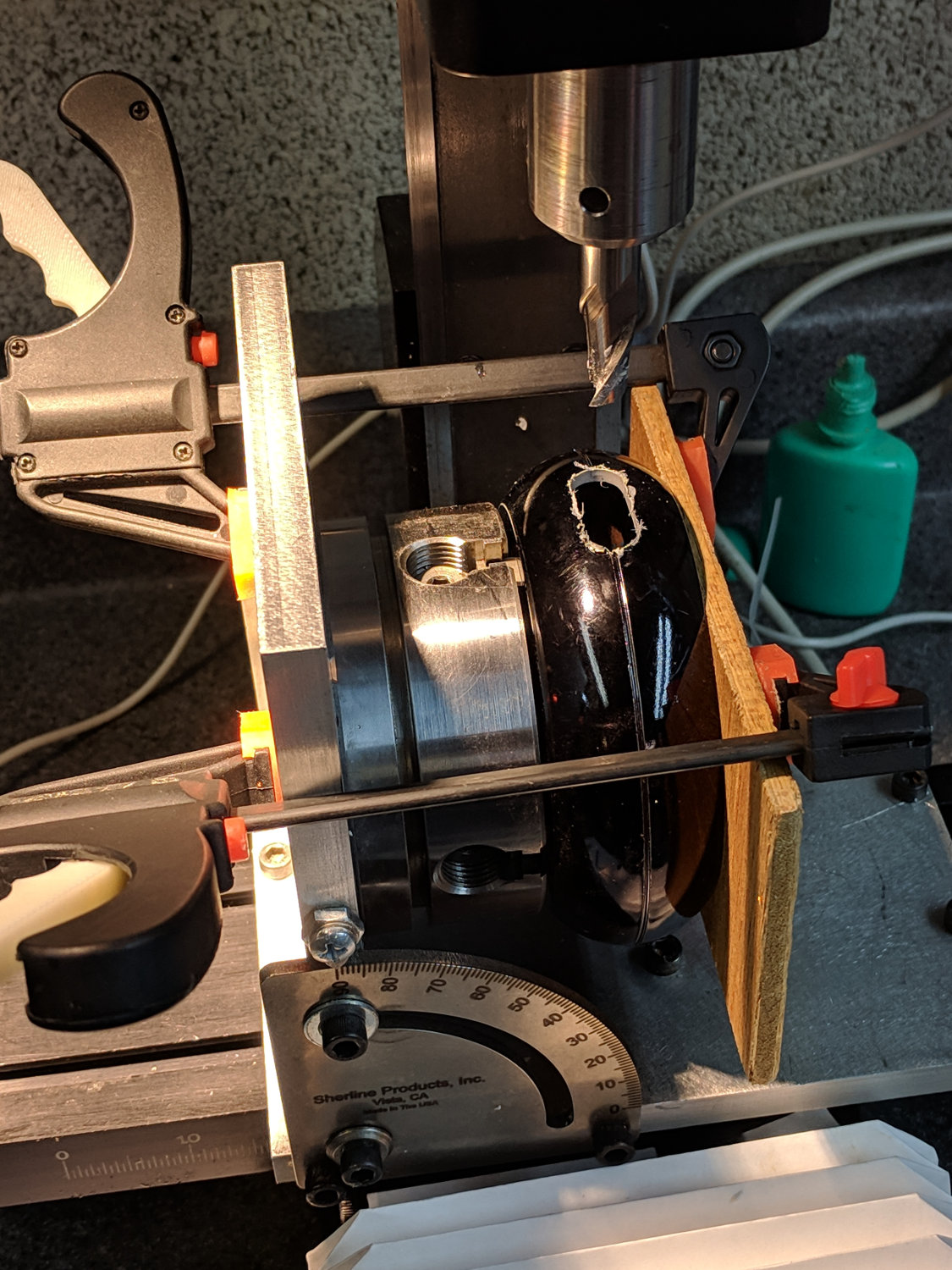
A test firing showed the heatsink needed more airflow, which didn’t come as much of a surprise, so I milled slots in the lamp head:
Ex-halogen Desk Lamp – vent slot milling
Deburring the holes, blackening the sides with a Sharpie, and tucking a bit of black window screen behind the opening made the vents look entirely professional.
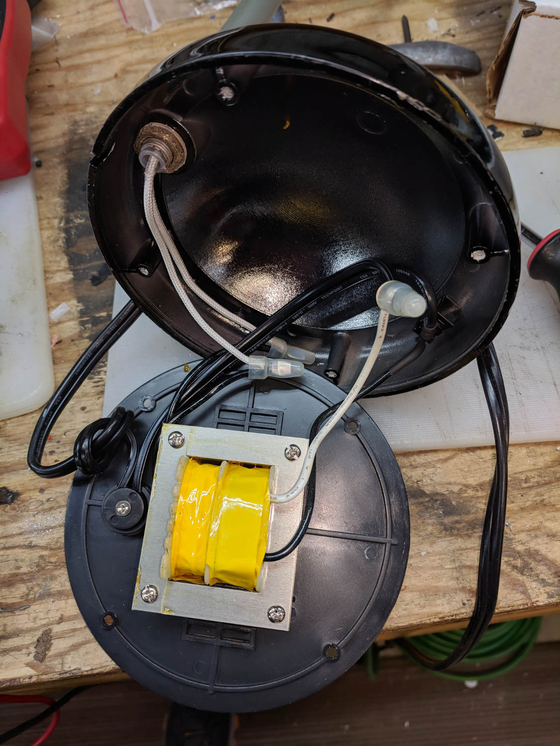
The small dome in the base originally cleared the transformer and now holds the entire 10 W LED driver, along with all the wiring, atop the counterweight sheets:
Ex-halogen Desk Lamp – base wiring
A cork pad covers the base for a bit of non-skid action:
Ex-halogen Desk Lamp – cork pad
I couldn’t convince myself filling in those sectors would improve anything, so I didn’t.
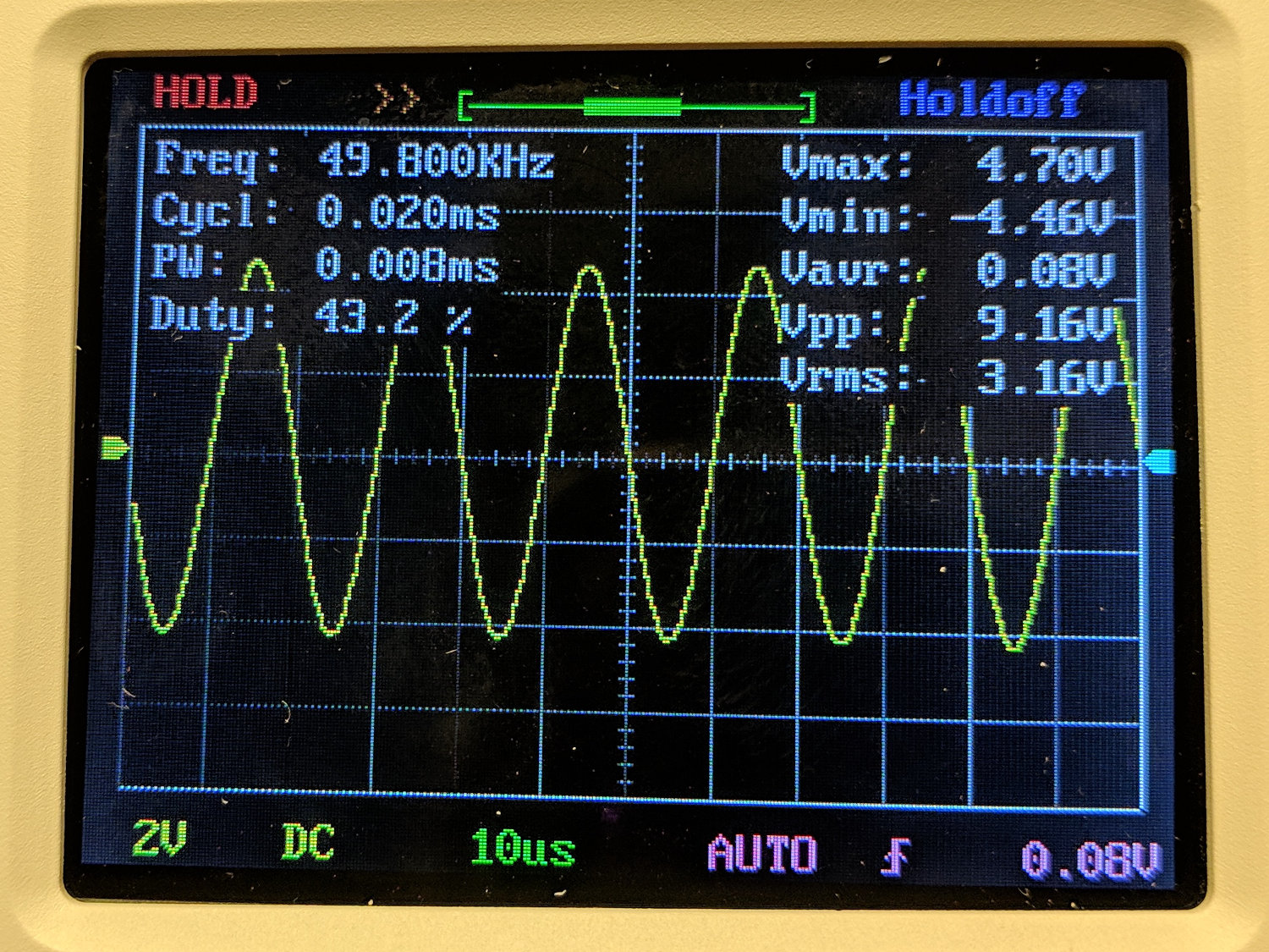
The DSO150 oscilloscope’s specs give a 200 kHz bandwidth, so a 50 kHz sine wave looks pretty good:
DSO150 – sine wave 50 kHz 10 us-div
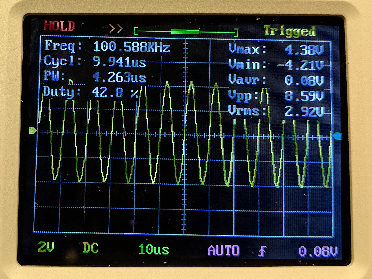
A 100 kHz sine wave looks chunky, with maybe 25 samples per cycle:
DSO150 – sine wave 100 kHz 10 us-div
The DSO150 tops out at 10 µs/div, so you can’t expand the waveform more than you see; 25 samples in 10 µs seems to be 2.5 Msample/s, exceeding the nominal 1 Msample/s spec. I have no explanation.
A 10 kHz square wave shows a blip just before each transition that isn’t on the actual signal:
DSO150 – square wave 10 kHz 20 us-div
At 50 kHz, there’s not much square left in the wave:
DSO150 – square wave 50 kHz 10 us-div
And, just for completeness, a 200 kHz square wave completely loses its starch:
DSO150 – square wave 200 kHz 10 us-div
A 10% (-ish) duty cycle pulse at 25 kHz has frequency components well beyond the scope’s limits, so it’s more of a blip than a pulse:
DSO150 – pulse 25 kHz 10 us-div
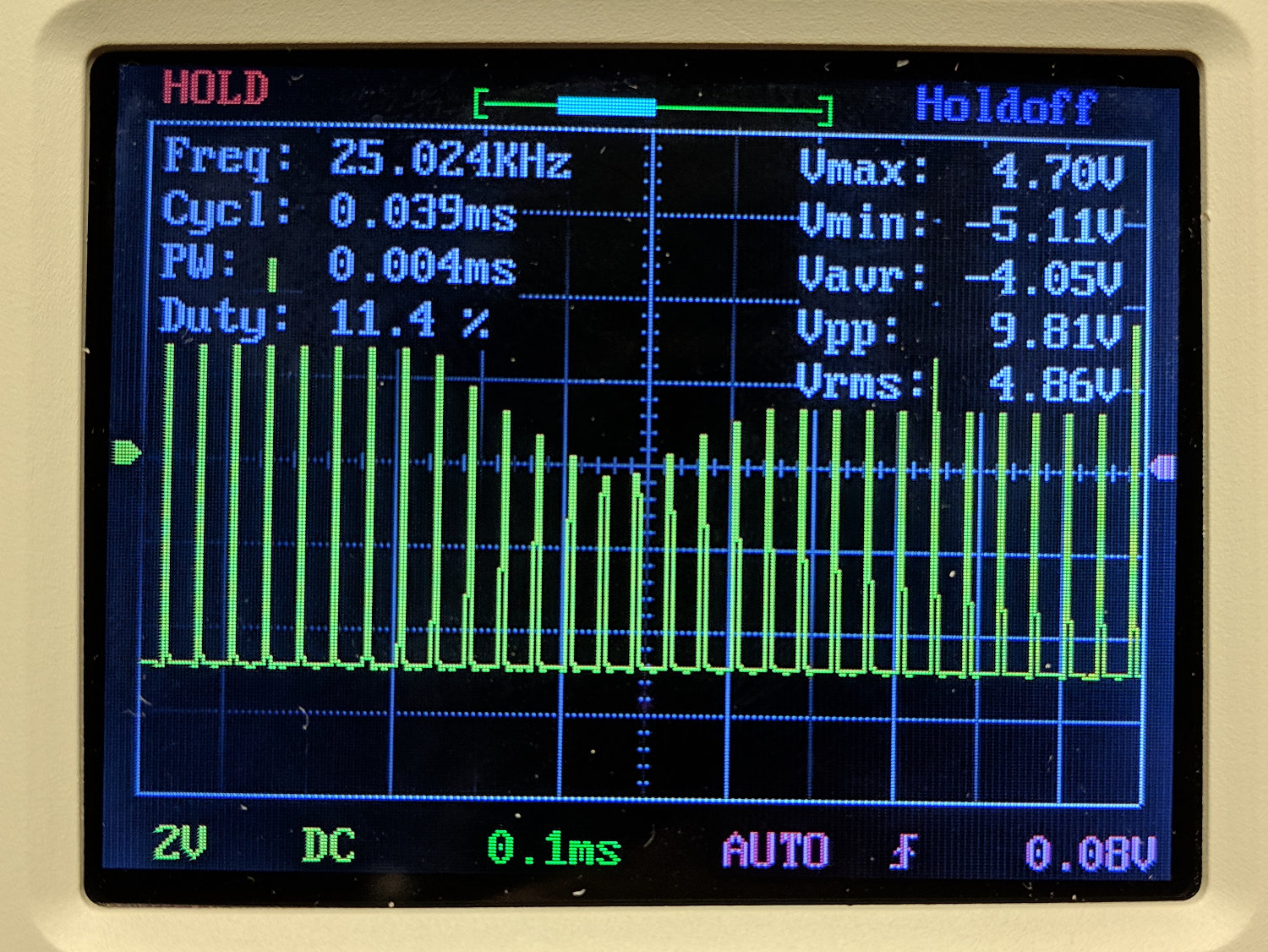
The pulse repetition frequency beats with the scope sampling and sweep speeds to produce weird effects:
DSO150 – pulse 25 kHz 100 us-div
Tuning the pulse frequency for maximum weirdness:
DSO150 – pulse 15 kHz 200 us-div
None of this is unique to the DSO150, of course, as all digital scopes (heck, all sampled-data systems) have the same issues. The DSO150’s slow sampling rate just makes them more obvious at lower frequencies.
Key takeaway: use the DSO150 for analog signals in the audio range, up through maybe 50 kHz, and it’ll produce reasonable results.
Using it for digital signals, even at audio frequencies, isn’t appropriate, because the DSO150’s low bandwidth will produce baffling displays.
The only scope mod consists of embedding a JST-ish connector in the back panel:
DSO150 battery hack – rear panel connector
Then soldering it to the battery pads and applying generous hot-melt glue blobs:
DSO150 battery hack – PCB power
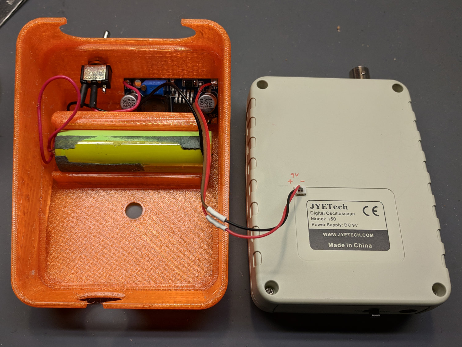
Add a scrap 18650 Li-Ion cell, a regulated boost converter, and a switch:
DSO150 battery hack – interior
The switch is directly below the DSO150 BNC connector to get a little protection for its handle, which would otherwise stick out in harm’s way. This being an afterthought, I drilled the switch hole, rather than modify the solid model.
Some testing with a bench supply showed that the DSO150 will not operate correctly from the voltages produced by a pair of lithium cells, despite what you’d think from looking at the case. Below 8 V, the internally generated negative supply becomes larger than the positive supply, so the 0 V point isn’t properly centered and the scope loses headroom for large signals; monitoring the internal 3.3 V test signal makes the problem painfully obvious.
More color commentary from my summary email:
Combining a case from Thingiverse with a Li-Ion cell and a regulated boost converter produces a portable scope.
The PCB has provision for battery input, so I drilled / filed a square hole for a teeny JST-ish connector on the back panel, secured it with a blob of hot melt glue, and globbed the wires onto the PCB battery pads.
The boost converter draws about 400 mA from the cell, so a 2500-ish mA·h cell should last Long Enough™. This is a scrap cell from the recycle box and gave out after maybe four hours.
It idles at 8 mA, so I drilled a hole in the back of the case for a toggle switch disconnecting the battery; you’d want the hole in the solid model. Perhaps a better converter would have lower idle current; you’d never be able to tell from the eBay descriptions.
Aaaaand it switches around 200 kHz under load, just barely beyond the scope bandwidth. It doesn’t add much noise to the signal, at least with a 50 Ω terminator jammed in the BNC, but the square-wave “cal” output looks awful at 50 mV/div; a real scope shows even more noise. I assume the noise comes directly from the logic supply; with luck, the DSO150’s analog circuitry has Good Enough™ filtering.
Which might not matter for logic-level and moderate analog signals, of course, which is the whole point of the DSO150.
Conspicuous by their absence: a Li-Ion cell protection PCB and any way to recharge the poor thing …
I’ve occasionally wanted a portable scope and now I have one!
I did a quick build of a JYE Tech DSO150 oscilloscope to see how it’d work in a proposed Squidwrench advanced soldering class / kit build session.
The main board requires adding only a few switches and headers, then removing a 0 Ω jumper resistor:
DSO150 – main board – bottom
The analog board requires a handful of 1/8 W resistors, various capacitors, switches, and the BNC connector:
DSO150 – main board – front
Some (lightly edited) color commentary from my summary email:
Just finished assembling the kit, which required two hours; I’m admittedly fussy. The one joint I missed on the input coupling switch required a complete disassembly, but all the rest worked fine.
The UI is much better than the DSO138.
Soldering the BNC connector requires lots of heat. My ordinary Hakko iron had inadequate grunt, so I deployed the hulking Radio Shack 150 W gun and did the job in seconds.
The resistors require a meter to measure them during installation, because they’re 1% 1/8 W jobbies with many teeny color strips in Chinese tints you’ve never seen before. I could not sort them visually, even with a lighted headband magnifier, and I know what I’m looking for.
The caps are marked, but using a meter builds confidence.
And, yes, the kit had all the right parts and they all worked. The instructions call for powering up the main board before starting assembly, then again after removing a 0 Ω jumper resistor, but that’s the extent of the “testing” required.
They recommend a flush cutter and I’d say it’s pretty much required. An ordinary diagonal cutter won’t get close enough to the PCB.
I needed an angle-tip tweezer to lay the PCB screws in place.
Don’t install the knob until the very last step and maybe wait until you’ve verified all the functions. You have been warned.
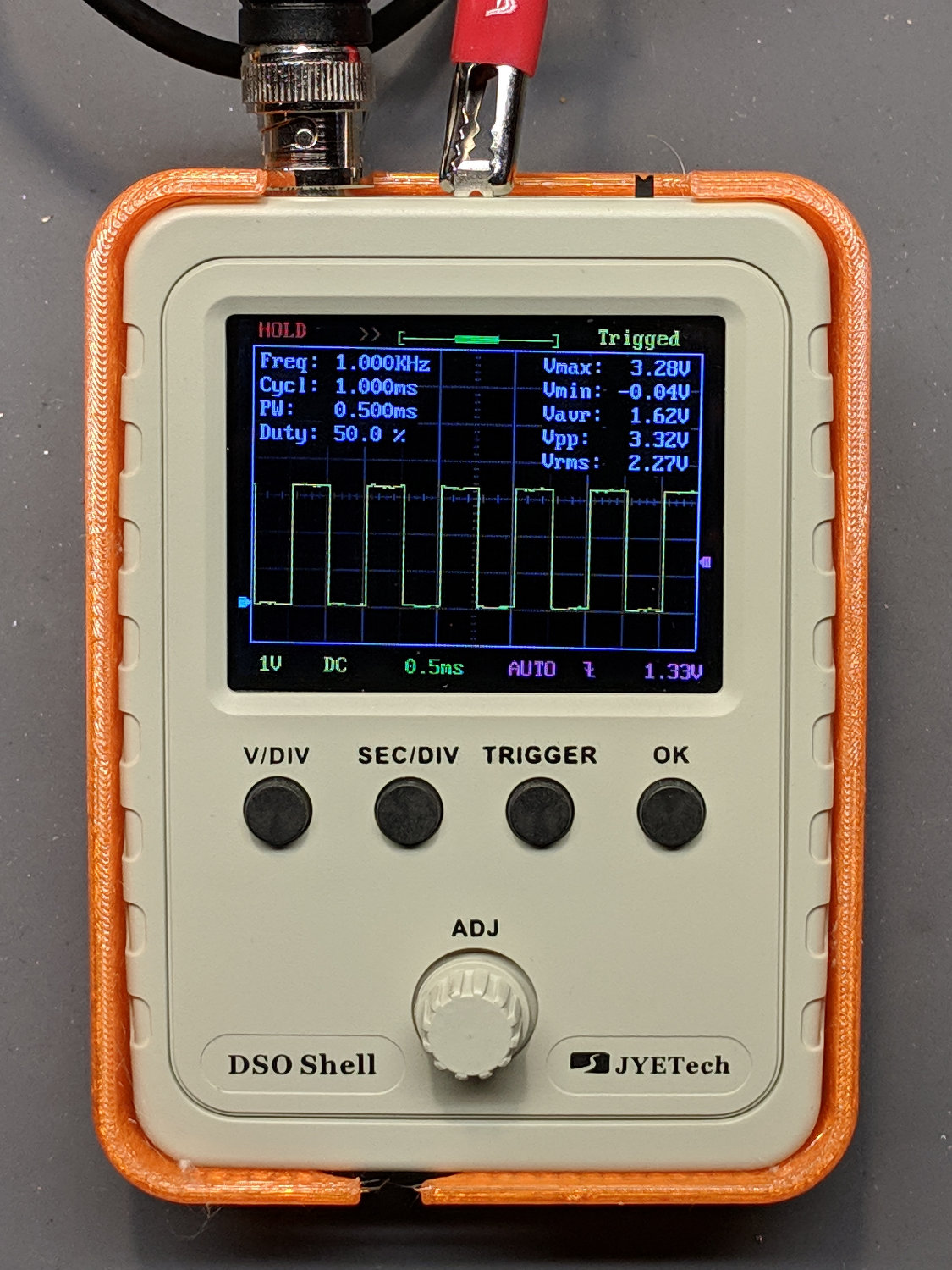
The minimum power supply voltage really is 8.0 V, not the 7.4 V from a not-quite-fully-charged pair of lithium cells. A 9 V alkaline battery will last a few minutes. A noisy boost converter / crappy 9 V wall wart translates directly into noise on the display, particularly on the internal calibration signal.
The “0.1 V” calibration signal turned out to be 150 mV, as measured on a real scope, at 1 kHz. The 3.3 V signal is closer to reality. Both are noisy from a noisy supply.
All in all, it’s a pretty good scope for thirty bucks!
Newbies will find it a challenging three hour build, for sure.
cd /etc/ImageMagick-6/
sudo cp policy.xml policy.xml.base
sudo nano policy.xml
… change one line …
 policy domain="coder" rights="read|write" pattern="PDF"
It is completely unclear to me whether ImageMagick (as of ImageMagick 6.9.7-4 Q16 x86_64 20170114 ) requires or merely tolerates the vertical bar in place of commas, nor whether it’s in my best interest to replace "coder" with "*".
In any event, I can once again stuff bitmap images into PDF files.
Our Compact Edition of the OED doesn’t get much use these days, but Mary needed a magnifier for a class on quilt judging and the OED has one that seemed just about right:
OED Magnifier Box in drawer
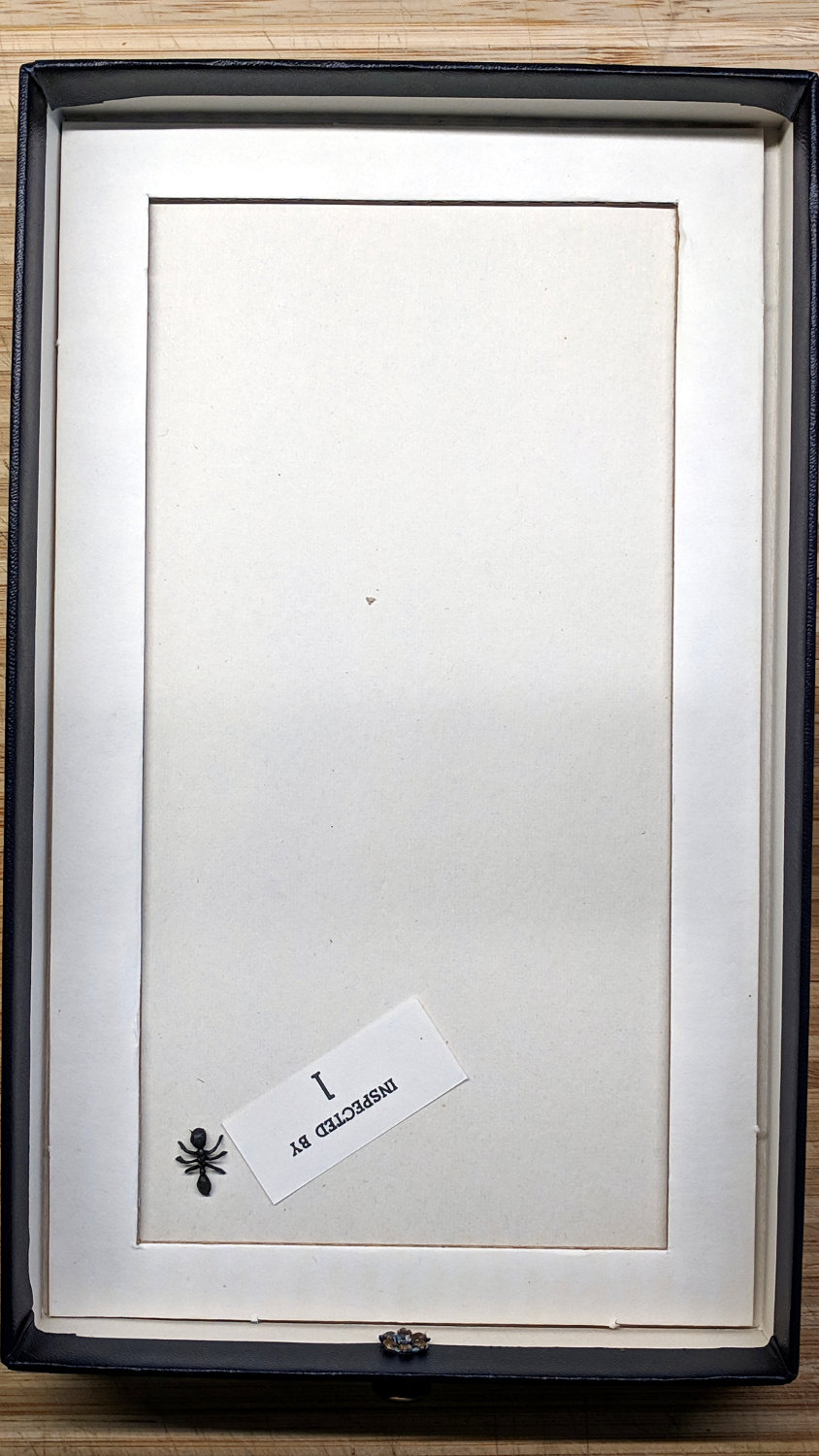
The magnifier comes in a removable box fitted neatly into the drawer, revealing a surprise underneath:
OED Magnifier drawer – plastic ant
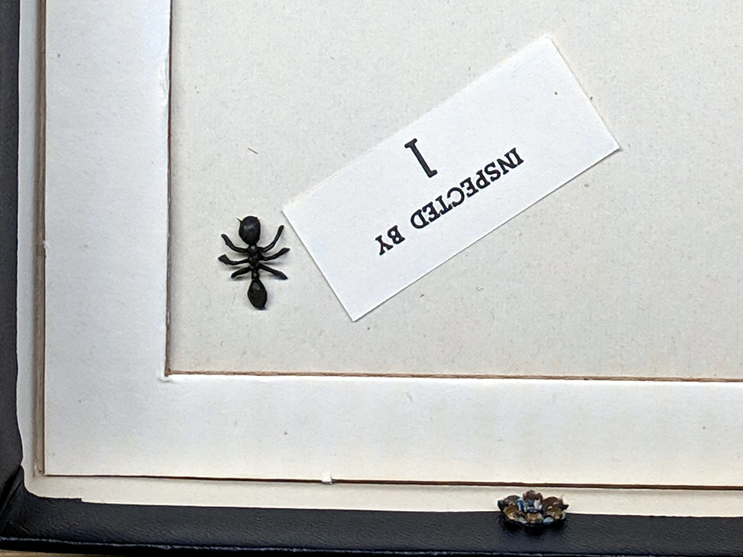
A detail view:
OED Magnifier drawer – plastic ant – detail
It’s a plastic ant from a bag in the Kiddie Surplus box my Shop Assistant grew up with and a pleasant reminder of long-ago days, carefully placed where only I’d ever see it.