Ed Nisley's Blog: Shop notes, electronics, firmware, machinery, 3D printing, laser cuttery, and curiosities. Contents: 100% human thinking, 0% AI slop.
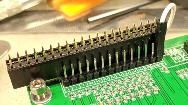
The white jumper plugs into the single +5 V pin in the row and is soldered to a straight wire running along the entire row of header pins. I pushed the black plastic strip to the bottom, soldered the wire along the pins atop it, then clipped off the pins so they’re about the right height when flush against the PCB.
Use a two-row socket to hold the new row in alignment with the existing header:
3018 CNC CAMTool – Endstop power mod – alignment
Slobber on some epoxy and let it cure:
3018 CNC CAMTool – Endstop power mod – epoxy curing
And then It Just Works™:
3018 CNC CAMTool – Endstop power mod – installed
Well, after you install the switches and tell GRBL to use them …
Reminder: If you intend to put limit switches on both ends of the axis travel, you mustclip the NC lead from both MBI switches. One switch per axis will work the way you expect and that’s how I’m using them here.
If you regard your new CNC 3018-Pro Router kit as a box of parts which could, with some adjustments and additional parts, become a small CNC router, you’re on the right track.
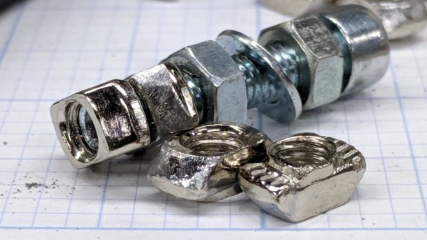
In my case, the aluminum extrusions arrived somewhat squashed inside their well-padded foam shipping carton, which leads me to believe the factory responsible for tapping the bolt holes in the ends must be a fairly nasty place. In any event, the hammerhead T-nuts for the gantry struts simply didn’t fit into some sections of the slots, although they worked fine elsewhere.
So, file a smidge off the rounded sides of a few nuts:
3018CNC – 2020 T-nuts – filed
Which let them slide into place and rotate properly despite the bent channel:
3018CNC – 2020 T-nuts – trial fit
The assembly instructions used a word I’d never encountered before:
3018CNC – Gantry plate position
Turns out ubiety is exactly correct, but … raise your hand if you’ve ever heard it in polite conversation. Thought so.
I’ve not noticed any harm from rounding off the position to 46 mm; just position both struts the same distance from the rear crossbar and it’s all good.
The struts behind the CAMTool CNC-V3.3 electronics board were also squashed, prompting a bit more filing:
3018CNC – CAMTool v3.3 board – trial fit
The CAMTool board is basically an Arduino-class microcontroller preloaded with GRBL 1.1f and surrounded with spindle / stepper driver circuits.
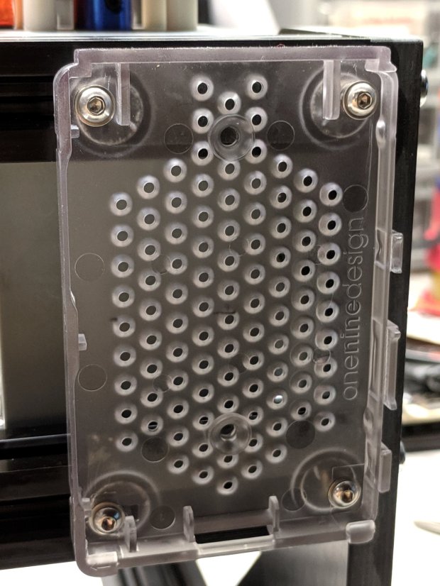
As with the MPCNC, I’ll dribble G-Code into it from a Raspberry Pi. Alas, the struts behind the CAMTool board are on 75 mm centers, but the Pi cases on hand have feet on 72-ish mm centers. Pay no attention to the surroundings, just drill the holes in the right spots:
3018CNC – RPi case – drilling
Add more T-nuts and short button head screws, with rubber pads between the case and the struts:
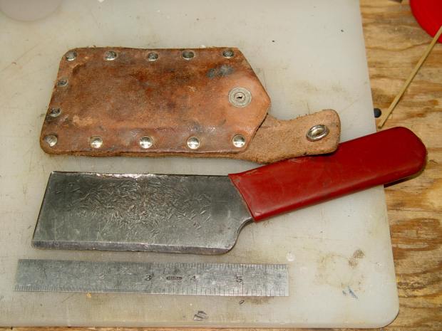
I got an email asking how the Kenmore Model 158 sewing machine’s foot pedal pivots worked. The notes on rebuilding the carbon disk rheostat and conjuring a Hall effect sensor show the innards, but here’s what you need to know to get there.
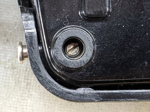
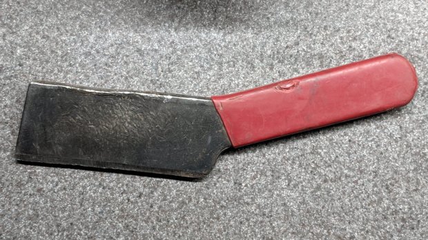
The pedal has a pair of pivots on the side closest to your foot, held in place with a small screw inside the two feet:
Kenmore 158 – Pedal pivot screw – in place
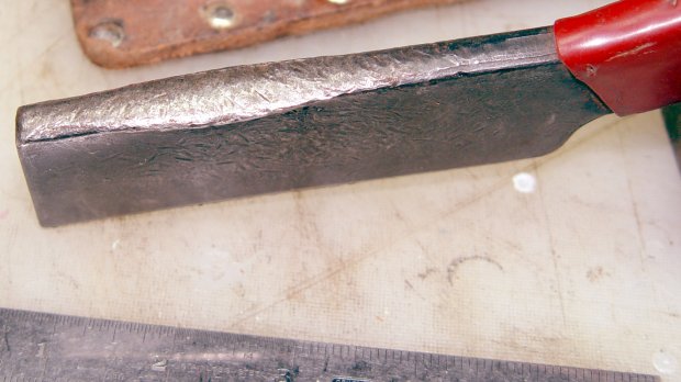
The screw fits into a notch in the unthreaded pin inserted from the side:
Kenmore 158 – Pedal pivot screw – disassembled
And that’s all there is to it!
Now, as happened to my correspondent, the pin can go missing, perhaps after the screw worked loose. Worst case, you’re looking at replacing both parts.
Being made in Japan (as ours were), the pedal has metric sizes: the unthreaded pin is 4 mm in diameter and 18 mm long and the setscrew has an M4×0.7 thread. You could replace the pin with an 18 mm (down to maybe 15 mm) long M4 screw. The threads would make a gritty pivot, but better than no pivot at all.
Better to get a longer M4 screw with an unthreaded section near the head, hacksaw it to the proper length, file to tidy up the cut end, maybe file a notch for the setscrew, and pop it in place. For tidiness, file off the slot / Philips / hex socket to eliminate the temptation to turn it out.
Worst case, a pair of plain old USA-ian 6-32 screws 3/4 inch long would make a sloppy fit. Don’t tell anybody I said so; that’d be barely better than nothin’ at all in there.
Lowe’s claims to have M4×0.7 setscrews (with a hex socket, not a slot) to secure the pin.
If my experience around here is any guide, however, Lowe’s / Home Depot / Walmart may claim to have metric hardware in stock, but the only way to know is to actually go there and rummage around in the specialty hardware section, inside the big steel cabinet with slide-out drawers filled with a remarkable disarray of ripped-open bags and misfiled parts.
Since the PiHole runs all the time, it now hosts an FTP server to stash snapshots from the cameras onto a 64 GB USB stick. I installed ProFTPD, which Just Worked with a few configuration tweaks:
UseIPv6             off
ServerName          "PiHole"
DefaultRoot         /mnt/cameras
RequireValidShell   off
ftp_snapshot=true
ftp_host="192.168.1.2"
ftp_port=21
ftp_username=$(/bin/hostname)
ftp_password="make up your own"
ftp_stills_dir=$(/bin/hostname)
The last line uses a separate directory for each camera, although they quickly ran into the FAT32 limit of 64 K files per directory; reformatting the USB stick with an ext3 filesystem solved that problem.
My high hopes for the UHMW bushing supporting the impeller lasted the better part of a day, because direct contact between the impeller and the motor bearing produced an absurdly loud and slowly pulsating rumble:
Bath Vent Fan – bushing installed
My hope that the UHMW would wear into a quieter configuration lasted a week …
Back in the Basement Shop, some free-air tinkering showed the impeller produced enough suction to pull itself downward along the shaft and jam itself firmly against the motor frame. My initial thought of putting a lock ring around the shaft to support the impeller turned out to be absolutely right.
So, make a small ring:
Bath Vent Fan – small lock ring – c-drill
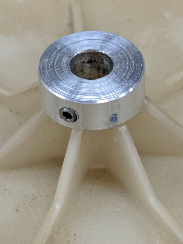
With a 4-40 setscrew in its side, perched atop the impeller for scale:
Bath Vent Fan – small lock ring – size
It just barely fits between the impeller and the motor frame:
Bath Vent Fan – small lock ring – installed
This reduced the noise, but the hole in the impeller has worn enough to let it rotate on the shaft and the rumble continued unabated. The correct way to fix this evidently requires a mount clamped to both the shaft and the impeller.
Fast-forward a day …
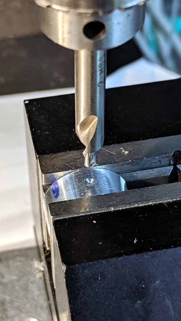
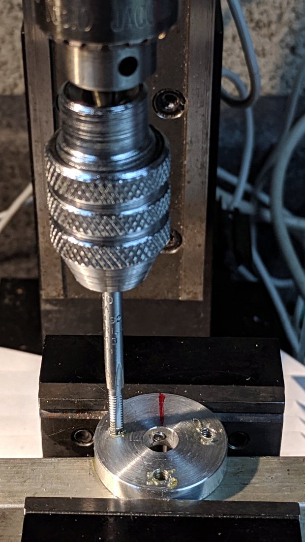
A careful look at the impeller shows seven radial ribs, probably to reduce the likelihood of harmonic vibrations. After a bit of dithering, I decided not to worry about an off-balance layout, so the screws sit on a 9 mm radius at ±102.9° = 2 × 360°/7 from a screw directly across from the setscrew in another slice from the 1 inch aluminum rod:
Bath Vent Fan – mount ring – tapping
Centered on the disk and using LinuxCNC’s polar notation, the hole positions are:
As usual, I jogged the drill downward while slobbering cutting fluid. I loves me some good manual CNC action.
Put the mount on a 1/4 inch tube, stick it into the impeller, and transfer-punch the screw holes:
Bath Vent Fan – mount ring – impeller marking
Apparently, some years ago I’d cut three screws to just about exactly the correct length:
Bath Vent Fan – mount ring – test fit – bottom
I knew I kept them around for some good reason!
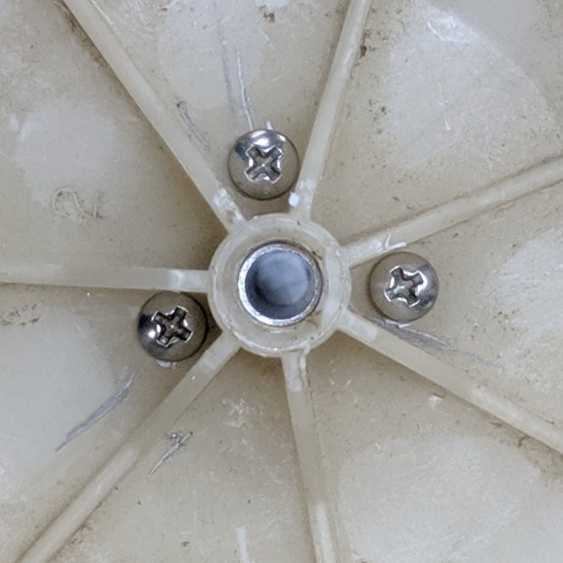
The 9 mm radius just barely fits the screw heads between the ribs:
Bath Vent Fan – mount ring – test fit – top
Some Dremel cutoff wheel action extended the motor shaft flat to let the setscrew rest on the bottom end:
Bath Vent Fan – mount ring – shaft flat
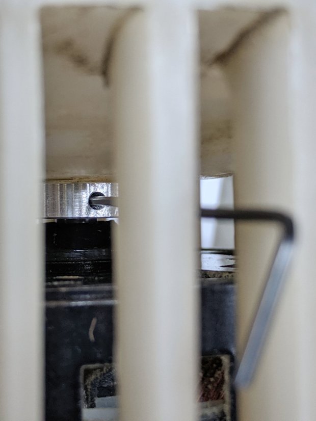
Then it all fit together:
Bath Vent Fan – mount ring – installed
The fan now emits a constant whoosh, rather than a pulsating rumble, minus all the annoying overtones. It could be quieter, but it never was, so we can declare victory and move on.
Dropping fifty bucks on a replacement fan + impeller unit would might also solve the problem, but it just seems wrong to throw all that hardware in the trash.
And, despite making two passes at the problem before coming up with a workable solution, I think that’s the only way (for me, anyhow) to get from “not working” to “good as it ever was”, given that I didn’t quite understand the whole problem or believe the solution at the start.
But it should be painfully obvious why I don’t do Repair Cafe gigs …
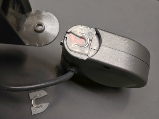
My collection of old USB cameras emitted a Logitech Quickcam for Notebooks Deluxe, with a tag giving a cryptic M/N of V-UGB35. Given Logitech’s penchant for overlapping names, its USB identifiers may be more useful for positive ID:
ID 046d:08d8 Logitech, Inc. QuickCam for Notebook Deluxe
It works fine as a simple V4L camera and its 640×480 optical resolution may suffice for simple purposes, even if it’s not up to contemporary community standards.
The key disassembly step turned out to be simply pulling the pivoting base off, then recovering an errant spring clip from the Laboratory Floor:
Logitech V-UGB35 USB Camera – mount removed
The clips have a beveled side and fit into their recesses in only one orientation; there’s no need for brute force.
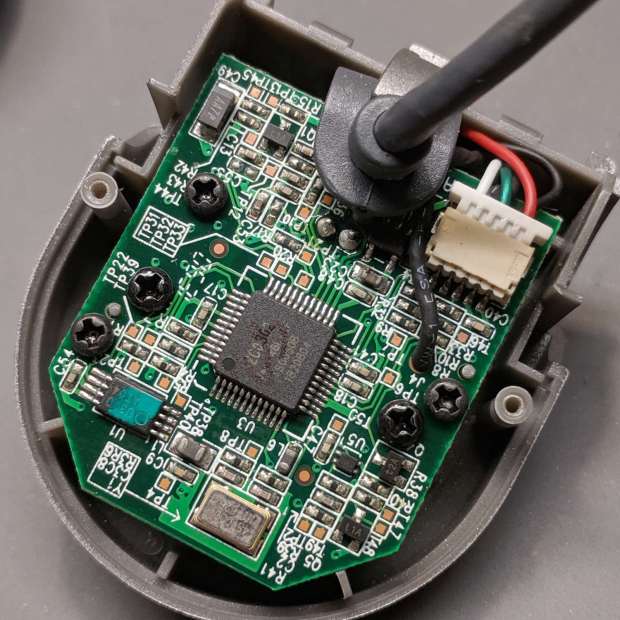
Removing the two obvious case screws reveals the innards:
Logitech V-UGB35 USB Camera – PCB rear
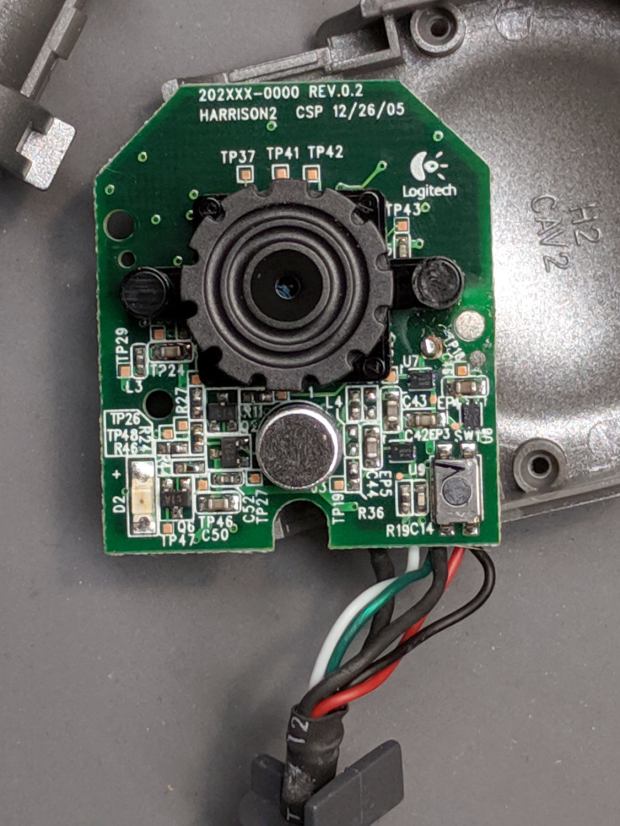
Three more screws secure the PCB:
Logitech V-UGB35 USB Camera – PCB front
The ribbed focus knob around the lens makes it more useful than a nominally fixed-focus camera.