The Smell of Molten Projects in the Morning

Ed Nisley's Blog: Shop notes, electronics, firmware, machinery, 3D printing, laser cuttery, and curiosities. Contents: 100% human thinking, 0% AI slop.

Author: Ed

  • Staedtler Mars Masterbow 551 02 WP: Assembly & Tweakage

    Staedtler Mars Masterbow 551 02 WP: Assembly & Tweakage

    The corners of Mary’s current quilt project need a 16 inch diameter circle, but my Drawer o’ Drawing Tools that should hold the trammel (distinct from trommel) point & pencil for a steel rule came up empty. While the TEC drawing kit has an extension leg for its compass, IMO it’s entirely too flexy for general use.

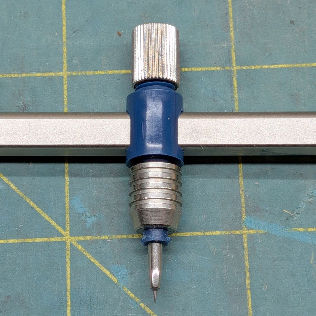
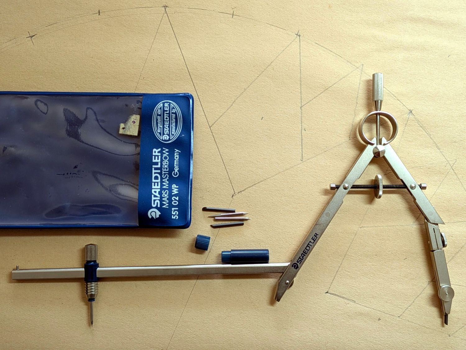
    Further heap probes produced a Staedtler Mars Masterbow 551 02 WP compass with a robust extension leg:

    Staedtler Masterbow - 551 02 WP assembled
    Staedtler Masterbow – 551 02 WP assembled

    It was likely a surplus deal and, to the best of my knowledge, has never been used, so that picture documents how the extension leg fits into the compass. It arrived with the lead in that compass leg, causing some confusion.

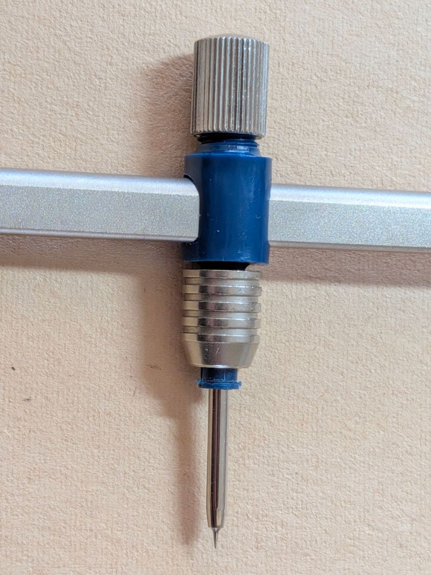
    The key is to remove the point from that leg, insert the extension leg into the hole, then tighten the screw to clamp the leg in place:

    Staedtler Masterbow - leg socket
    Staedtler Masterbow – leg socket

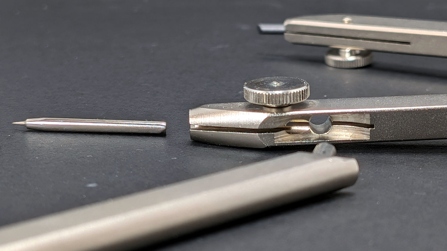
    The collet holding the point was either manufactured incorrectly (which I find hard to believe, because Staedtler in a package embossed “Western Germany”) or suffered damage along the way, as the only point fitting into it stuck out much too far:

    Staedtler Masterbow - bow collet wrong point
    Staedtler Masterbow – bow collet wrong point

    The small container in the top picture held two spare leads and two other points:

    Staedtler Masterbow - point assortment
    Staedtler Masterbow – point assortment

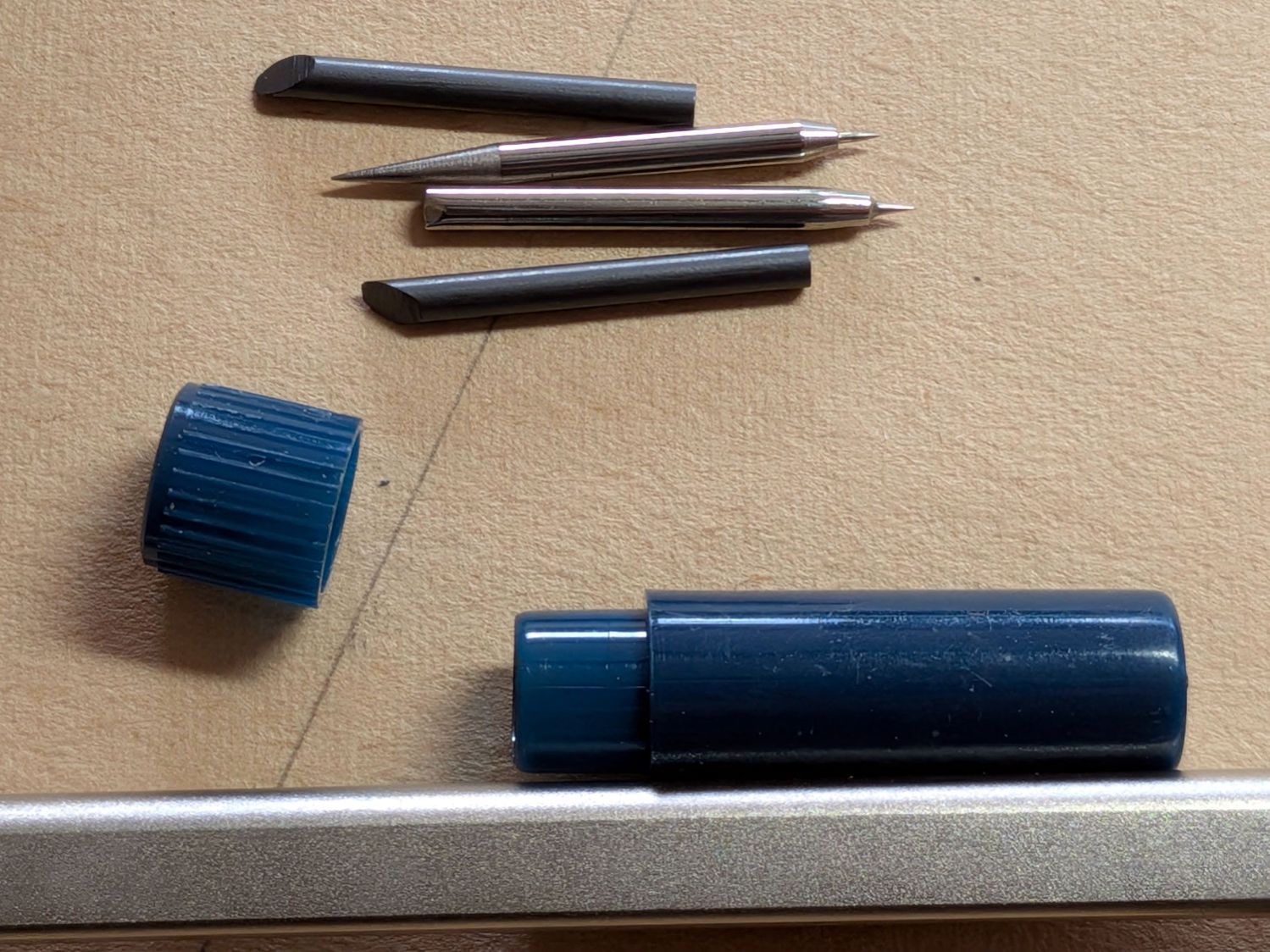
    It turns out the blunt end of the bottom point should fit into the collet, but I had to ream the collet jaws with a (hand-turned in a pin vise) 2.1 mm drill to let that happen:

    Staedtler Masterbow - bow collet resized
    Staedtler Masterbow – bow collet resized

    Then everything lined up correctly and drawing could proceed, although the collet closer doesn’t (seem to) contribute anything to the proceedings.

    The thumbscrew adjustment on the compass makes it much more rigid, even with the extension leg sticking out there for an 8 inch span.

    I can (now) put the lead in the bow collet and the point in the compass, but IMO it’s easier to hold the compass while drawing around the circle. Your mileage, in the unlikely event you have one of these, may vary.

    They definitely don’t make them like that any more …

  • Prusa MK4 Foam Feet: Embiggened

    Prusa MK4 Foam Feet: Embiggened

    It turns out the Prusa MK4 weighs enough to squish my add-on foam feet to about half their original thickness:

    Prusa MK4 Foam Feet - embiggened
    Prusa MK4 Foam Feet – embiggened

    The two in the front are 30×30 mm and the shorter (more squished) foot was under the right rear of the MK4 where the power supply lives.

    The larger feet (one installed) are 60×60 mm and, with the same weight supported on four times the area, should squish much less.

    Stipulated: I can’t hear the difference either way.

    This project was precipitated by finding a large scrap of exercise mat foam in a place where it shouldn’t have been.

  • Magnetic Stirrer: Interior

    Magnetic Stirrer: Interior

    Of late, the magnetic stirrer mixing my morning cocoa occasionally doesn’t start spinning when I turn it on, which calls for some investigation.

    Removing the four obvious screws concealed under the rubber feet and prying off bottom cover reveals the trivial innards:

    Magnetic stirrer - interior
    Magnetic stirrer – interior

    The speed adjustment pot holds the little circuit board in place, with the green LED setting its jaunty angle.

    The motor spins a pair of neodymium magnets:

    Magnetic stirrer - magnet holder
    Magnetic stirrer – magnet holder

    I expected a gearbox instead of the direct drive setup.

    Perhaps those whirling neodymium magnets have been slowly demagnetizing the motor’s internal (alnico?) magnets.

    The motor brushes seem to be a pair of stiff wires, rather than carbon blocks, contacting the commutator, the wear from which may account for motor’s decreasing startup enthusiasm. Even though I didn’t expect a BLDC motor, this one may have been overly cheapnified.

    Perhaps kickstarting the motor with the steel fork I use to fish the stirrer magnet out of the mug will get the thing going.

  • Tax Season: 2026 Edition

    Tax Season: 2026 Edition

    Having recently filed our income taxes, this email came as a mild surprise:

    IRS Audit email
    IRS Audit email

    The From field seemed a bit sketchy, but, hey, maybe the IRS subcontracted their email vendor after having lost much of their staff in the name of efficiency.

    The attached PDF document seemed scant:

    IRS Audit document
    IRS Audit document

    Yeah, I’m definitely clicking that link …

  • Generator Cover Screw Knob

    Generator Cover Screw Knob

    The latches holding the side cover of the portable generator in place work well enough that I never tighten the cover screws, but sometimes one will vibrate itself into place and require less than one turn of a screwdriver to release. Given that I put a knob on the air filter screw, a pair of knobs on the side cover screws makes sense:

    Generator Cover Screw Knob - installed
    Generator Cover Screw Knob – installed

    Those are custom screws! The narrow neck keeps them captive in the cover, which is a Good Thing™.

    These knobs obviously descend from the air filter knob, with less knurling and a short shaft to clear the recess in the cover:

    Generator Cover Screw Knob - solid model
    Generator Cover Screw Knob – solid model

    Unlike the air filter knob, the double-sided tape gluing these to their screws isn’t continually compressed, so the knobs may eventually shake off. Should that happen, I’ll deploy epoxy.

    The OpenSCAD source code:

    // Generator cover screw knob
    // Ed Nisley - KE4ZNU
    // 2026-03-13
    
    include <BOSL2/std.scad>
    
    /* [Hidden] */
    
    // Screw head dome
    
    HeadHeight = 2.0;
    HeadOD = 10.8;
    
    DomeRadius = (HeadHeight^2 + (HeadOD^2)/4) / (2*HeadHeight);
    echo(DomeRadius=DomeRadius);
    
    KnobOD = 15.0;
    KnobLength = 10.0;
    
    ShaftOD = HeadOD;
    ShaftLength = 7.0;
    
    RimFudge = 0.3;   // ensures a printable edge
    
    // Build it
    
    difference() {
      cyl(h=KnobLength, r=KnobOD/2,anchor=BOTTOM,texture="trunc_pyramids",tex_size=[3.0,KnobLength/3]) position(TOP)
        cyl(ShaftLength,d=ShaftOD,anchor=BOTTOM);
      up(KnobLength + ShaftLength - HeadHeight + RimFudge)
        spheroid(r=DomeRadius,circum=true,style="icosa",anchor=BOTTOM);
    }
    
    
  • Wobbly Clothes Rack Repair

    Wobbly Clothes Rack Repair

    A clothes rack Mary intended use with some work-in-progress quilts seemed entirely too wobbly for the purpose, so I tried tightening its screws. This did not go well, as some of the threaded inserts sunk into the vertical bars spun freely and, with a bit of persuasion, pulled straight out of their sockets:

    Clothes rack screws - threaded insert penetrating oil
    Clothes rack screws – threaded insert penetrating oil

    The reddish fluid is Kroil penetrating oil I hoped would free the screws from the corrosion locking them into the inserts. After an overnight soak, they still required force majeure:

    Clothes rack screws - threaded insert in vise
    Clothes rack screws – threaded insert in vise

    The two inserts on the left came from the top of the rack and the other two from the bottom:

    Clothes rack screws - threaded insert corrosion
    Clothes rack screws – threaded insert corrosion

    Similar inserts have a hex drive recess and, because these are for 1/4-20 screws, I expected an inch size hex key. Nope, they want a hard metric 6 mm:

    Clothes rack screws - threaded insert reformed
    Clothes rack screws – threaded insert reformed

    I cleaned up the corroded inserts by the simple expedient of tapping them firmly onto the 6 mm wrench held in the vise:

    Clothes rack screws - threaded insert hex reforming
    Clothes rack screws – threaded insert hex reforming

    The crud around the bottom fell out of previous contestants during their reformation.

    I considered epoxying the inserts in place, but settled for tucking a thick paper shim into each hole:

    Clothes rack screws - threaded insert shim
    Clothes rack screws – threaded insert shim

    They’re entirely snug right now and, should they work loose, I’ll coat the hole with epoxy, roll up another shim, screw the insert in place, await curing, then declare victory and hope nobody must ever remove them.

    The 1/4-20 screws in the top member sit deep in recesses that surely had decorative wood plugs when the rack left the factory. Alas, they’re long gone, which may have let water / moisture corrode the screws + inserts . I’m not much good for “decorative” items, so this must suffice:

    Clothes Rack Screw Covers - solid model
    Clothes Rack Screw Covers – solid model

    A snippet of double-sided tape on one side of the hole keeps them in place:

    Clothes rack screws - cover installed
    Clothes rack screws – cover installed

    They look better in person …

    The trivial OpenSCAD source code:

    // Clothes rack screw cover
    // Ed Nisley - KE4ZNU
    // 2026-03-13
    
    include <BOSL2/std.scad>
    
    /* [Hidden] */
    
    NumSides = 4*3*3*4;
    $fn=NumSides;
    
    //----------
    // Build it
    //  … with magic numbers from the rack
    
    cyl(3.0,d=16.7,chamfer1=1.0,anchor=BOTTOM) position(TOP)
      cyl(6.0,d=12.9,chamfer2=1.0,anchor=BOTTOM);


  • Clover Mini-Iron Holder: Revised

    Clover Mini-Iron Holder: Revised

    The 3D printed Clover Mini-Iron holder served well over the last decade (!), even after one of Mary’s buddies misplaced the iron during a quilting bee:

    Clover MCI-900 Mini Iron holder - melted
    Clover MCI-900 Mini Iron holder – melted

    She asked for a new holder that put the iron at a higher angle for easier gripping, which required only slight tinkering to boot the OpenSCAD code into the current decade:

    Clover MCI-900 Mini Iron holder - higher angle
    Clover MCI-900 Mini Iron holder – higher angle

    The letters stand one layer proud of the surface just to see what that looked like. I think it’s a nice touch.

    The alert reader will note the cord end isn’t quite snugged into its recess. In normal use, the cord hangs over the edge of the sewing table and pulls the iron into place.

    I embiggened the base to fit an aluminum plate from the stockpile, because that same cord tends to pull the holder around on the table. The plate puts enough weight on the silicone rubber feet to hold it firmly in place.

    A layer of good double-stick tape strips bonds the aluminum plate to the PETG iron holder, after I once again discovered that craft adhesive sheets do not bond to PETG.