Spotted on a recent trip past the Capital Region Welcome Center, one of the banners seemed quite unlike the others:

Maybe if we were dog people, it’d be less offputting.
Puts me in mind of being So Poughkeepsie.
The Smell of Molten Projects in the Morning
Ed Nisley's Blog: Shop notes, electronics, firmware, machinery, 3D printing, laser cuttery, and curiosities. Contents: 100% human thinking, 0% AI slop.

Spotted on a recent trip past the Capital Region Welcome Center, one of the banners seemed quite unlike the others:
Maybe if we were dog people, it’d be less offputting.
Puts me in mind of being So Poughkeepsie.
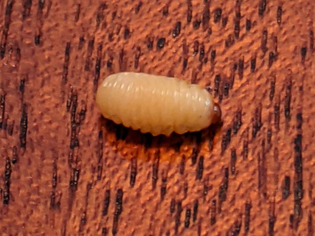
I spotted this little gadget chugging steadily across a table in the living room:
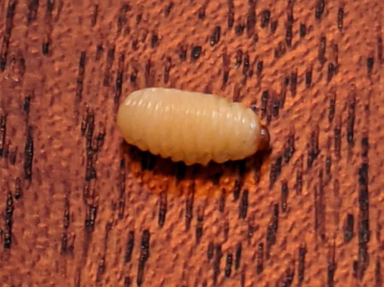
Nearby, two of its friends / siblings / clones remained near their landing craft:

They’re about 5 mm long and, although there are no larva-size holes visible in the chestnuts tucked inside the burr, that’s definitely where they started their journey.
A few hours later, the rest of the crew bailed out:
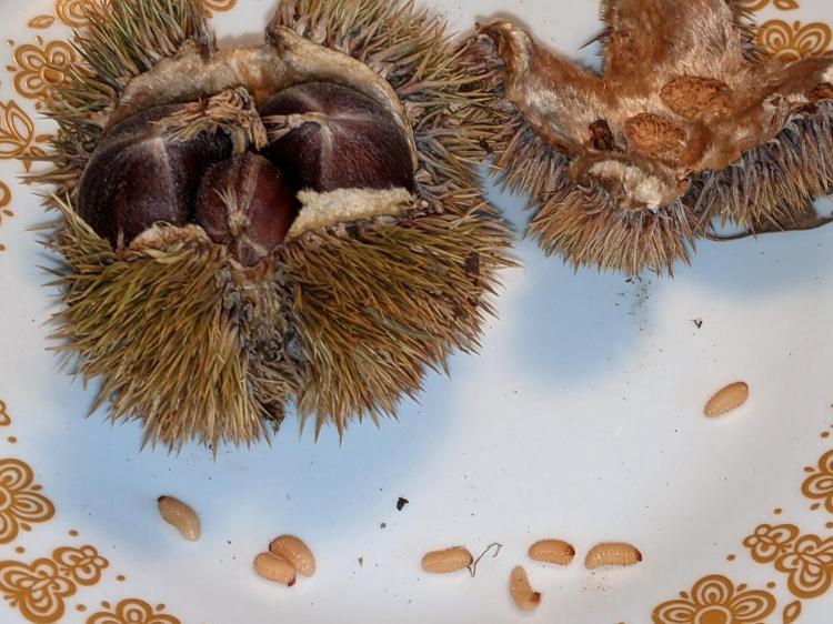
The exit hole must be on a nut under the curve of the husk, but they’re sufficiently squishy to wriggle their way out. The little brown dot over on the left belongs to the top larva of a pair queued in the exit corridor:

I lost count at 18. There’s surely more where they came from, so I replaced the plate with a bowl to reduce the quantum tunneling probability.
In an ideal world, they’d grow up to be chestnut weevils, but I put them out near the suet feeder and, a few hours later, my offering was accepted.

The values written to the I²C register controlling the Arducam Motorized Focus Camera lens position are strongly nonlinear with distance, so a simple linear increment / decrement isn’t particularly useful. If one had an equation for the focus value given the distance, one could step linearly by distance.
So, we begin.
Set up a lens focus test range amid the benchtop clutter with found objects marking distances:

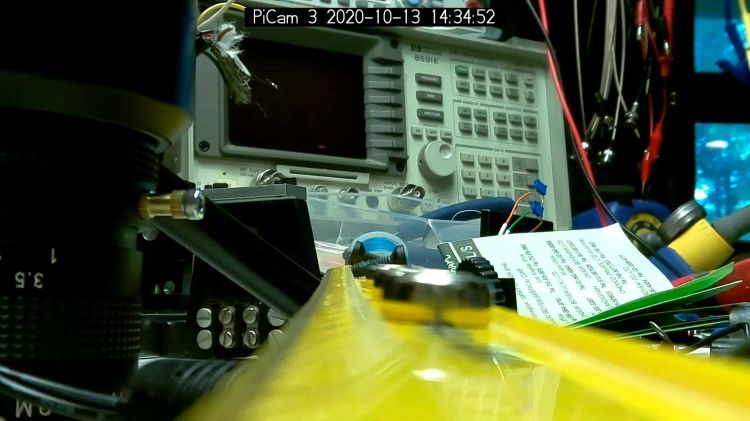
Fire up the video loopback arrangement to see through the camera:

The camera defaults to a focus at infinity (or, perhaps, a bit beyond), corresponding to 0 in its I²C DAC (or whatever). The blue-green scenery visible through the window over on the right is as crisp as it’ll get through a 5 MP camera, the HP spectrum analyzer is slightly defocused at 80 cm, and everything closer is fuzzy.
Experimentally, the low byte of the I²C word written to the DAC doesn’t change the focus much at all, so what you see below comes from writing a focus value to the high byte and zero to the low byte.
For example, to write 18 (decimal) to the camera:
i2cset -y 0 0x0c 18 0That’s I²C bus 0 (through the RPi camera ribbon cable), camera lens controller address 0x0c (you could use 12 decimal), focus value 18 * 256 + 0 = 0x12 + 0x00 = 4608 decimal.
Which yanks the focus inward to 30 cm, near the end of the ruler:
The window is now blurry, the analyzer becomes better focused, and the screws at the far end of the yellow ruler look good. Obviously, the depth of field spans quite a range at that distance, but iterating a few values at each distance gives a good idea of the center point.
A Bash one-liner steps the focus inward from infinity while you arrange those doodads on the ruler:
for i in {0..31} ; do let h=i*2 ; echo "high: " $h ; let rc=1 ; until (( rc < 1 )) ; do i2cset -y 0 0x0c $h 0 ; let rc=$? ; echo "rc: " $rc ; done ; sleep 1 ; doneWrite 33 to set the focus at 10 cm:

Then write 55 for 5 cm:

The tick marks show the depth of field might be 10 mm.
Although the camera doesn’t have a “thin lens” in the optical sense, for my simple purposes the ideal thin lens equation gives some idea of what’s happening. I think the DAC value moves the lens more-or-less linearly with respect to the sensor, so it should be more-or-less inversely related to the focus distance.
Take a few data points, reciprocate & scale, plot on a doodle pad:

Dang, I loves me some good straight-as-a-ruler plotting action!
The hook at the upper right covers the last few millimeters of lens travel where the object distance is comparable to the sensor distance, so I’ll give the curve a pass.
Feed the points into a calculator and curve-fit to get an equation you could publish:
DAC MSB = 10.8 + 218 / (distance in cm)
        = 10.8 + 2180 / distance in mm)
Given the rather casual test setup, the straight-line section definitely doesn’t support three significant figures for the slope and we could quibble about exactly where the focus origin sits with respect to the camera.
So this seems close enough:
DAC MSB = 11 + 2200 / (distance in mm)Anyhow, I can now tweak a “distance” value in a linear-ish manner (perhaps with a knob, but through evdev), run the equation, send the corresponding DAC value to the camera lens controller, and have the focus come out pretty close to where it should be.
Now, to renew my acquaintance with evdev …

Much to our utter astonishment, this appeared on the driveway:

We’ve since found half a dozen chestnut burrs in the yard, which means at least two trees (it takes two to cross-fertilize) are growing in the immediate area.
We originally thought they were American Chestnuts, but Mary (being a Master Gardener) found enough references including comparative burr pictures to convince us they’re Chinese Chestnuts.
We’ve seen squirrels carrying the burrs in their mouths from the trees to wherever they bury their food supply, as shown by this gnawed spot on the other side of the burr:
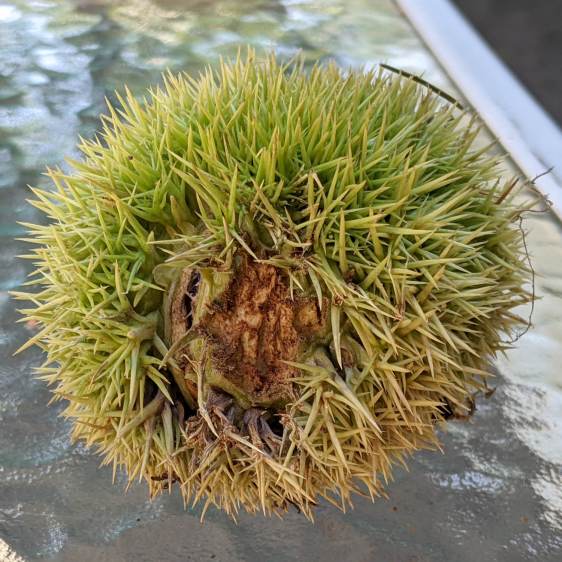
I regard this as conclusive proof that squirrels either have no sense of pain or no lips, because I can’t imagine carrying that thing in my hand, let alone gnawing through it to extract the nuts inside.
Each burr contains three nuts, although this empty husk shows some nuts can fail to fill out:

We don’t know where the trees are, but the squirrels seem to carry the burrs across our yard from north to south, so they can’t be too far from us or each other.
Despite our conclusion, it’s faintly possible they’re American Chestnuts, in which case they’re definitely survivors!

Thinking about using a rotary encoder to focus a Raspberry Pi lens led to a testbed:

There’s not much to it, because the RPi can enable pullup resistors on its digital inputs, whereupon the encoder switches its code bits to common. The third oscilloscope probe to the rear syncs on a trigger output from my knob driver.
I started with the Encoder library from PyPi, but the setup code doesn’t enable the pullup resistors and the interrupt (well, it’s a callback) handler discards the previous encoder state before using it, so the thing can’t work. I kept the overall structure, gutted the code, and rebuilt it around a state table. The code appears at the bottom, but you won’t need it.
Here’s the problem, all in one image:
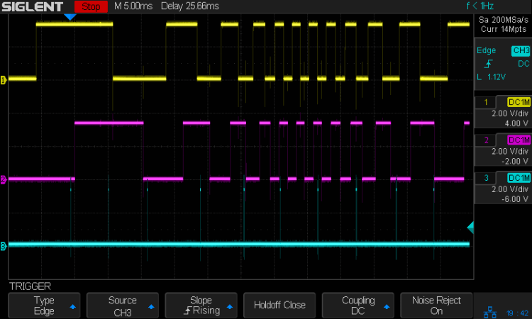
The top two traces are the A and B encoder bits. The bottom trace is the trigger output from the interrupt handler, which goes high at the start of the handler and low at the end, with a negative blip in the middle when it detects a “no motion” situation: the encoder output hasn’t changed from the last time it was invoked.
Over on the left, where the knob is turning relatively slowly, the first two edges have an interrupt apiece. A detailed view shows them in action (the bottom half enlarge the non-shaded part of the top half):

Notice that each interrupt occurs about 5 ms after the edge causing it!
When the edges occur less than 5 ms apart, the driver can’t keep up. The next four edges produce only three interrupts:

A closer look at the three interrupts shows all of them produced the “no motion” pulse, because they all sampled the same (incorrect) input bits:

In fact, no matter how many edges occur, you only get three interrupts:
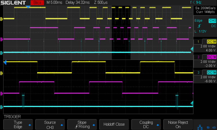
The groups of interrupts never occur less than 5 ms apart, no matter how many edges they’ve missed. Casual searching suggests the Linux Completely Fair Scheduler has a minimum timeslice / thread runtime around 5 ms, so the encoder may be running at the fastest possible response for a non-real-time Raspberry Pi kernel, at least with a Python handler.
If. I. Turn. The. Knob. Slowly. Then. It. Works. Fine. But. That. Is. Not. Practical. For. My. Purposes.
Nor anybody else’s purposes, really, which leads me to think very few people have ever tried lashing a rotary encoder to a Raspberry Pi.
So, OK, I’ll go with Nearer and Farther focusing buttons.
The same casual searching suggested tweaking the Python thread’s priority / niceness could lock it to a different CPU core and, obviously, writing the knob handler in C / C++ / any other language would improve the situation, but IMO the result doesn’t justify the effort.
It’s worth noting that writing “portable code” involves more than just getting it to run on a different system with different hardware. Rotary encoder handlers are trivial on an Arduino or, as in this case, even an ARM-based Teensy, but “the same logic” doesn’t deliver the same results on an RPi.
My attempt at a Python encoder driver + simple test program as a GitHub Gist:
| # Rotary encoder test driver | |
| # Ed Nisley – KE4ZNU | |
| # Adapted from https://github.com/mivallion/Encoder | |
| # State table from https://github.com/PaulStoffregen/Encoder | |
| import RPi.GPIO as GPIO | |
| class Encoder(object): | |
| def __init__(self, A, B, T=None, Delay=None): | |
| GPIO.setmode(GPIO.BCM) | |
| self.T = T | |
| if T is not None: | |
| GPIO.setup(T, GPIO.OUT) | |
| GPIO.output(T,0) | |
| GPIO.setup(A, GPIO.IN, pull_up_down=GPIO.PUD_UP) | |
| GPIO.setup(B, GPIO.IN, pull_up_down=GPIO.PUD_UP) | |
| self.delay = Delay | |
| self.A = A | |
| self.B = B | |
| self.pos = 0 | |
| self.state = (GPIO.input(B) << 1) | GPIO.input(A) | |
| self.edges = (0,1,-1,2,-1,0,-2,1,1,-2,0,-1,2,-1,1,0) | |
| if self.delay is not None: | |
| GPIO.add_event_detect(A, GPIO.BOTH, callback=self.__update, | |
| bouncetime=self.delay) | |
| GPIO.add_event_detect(B, GPIO.BOTH, callback=self.__update, | |
| bouncetime=self.delay) | |
| else: | |
| GPIO.add_event_detect(A, GPIO.BOTH, callback=self.__update) | |
| GPIO.add_event_detect(B, GPIO.BOTH, callback=self.__update) | |
| def __update(self, channel): | |
| if self.T is not None: | |
| GPIO.output(self.T,1) # flag entry | |
| state = (self.state & 0b0011) \ | |
| | (GPIO.input(self.B) << 3) \ | |
| | (GPIO.input(self.A) << 2) | |
| gflag = '' if self.edges[state] else ' – glitch' | |
| if (self.T is not None) and not self.edges[state]: # flag no-motion glitch | |
| GPIO.output(self.T,0) | |
| GPIO.output(self.T,1) | |
| self.pos += self.edges[state] | |
| self.state = state >> 2 | |
| # print(' {} – state: {:04b} pos: {}{}'.format(channel,state,self.pos,gflag)) | |
| if self.T is not None: | |
| GPIO.output(self.T,0) # flag exit | |
| def read(self): | |
| return self.pos | |
| def read_reset(self): | |
| rv = self.pos | |
| self.pos = 0 | |
| return rv | |
| def write(self,pos): | |
| self.pos = pos | |
| if __name__ == "__main__": | |
| import encoder | |
| import time | |
| from gpiozero import Button | |
| btn = Button(26) | |
| enc = encoder.Encoder(20, 21,T=16) | |
| prev = enc.read() | |
| while not btn.is_held : | |
| now = enc.read() | |
| if now != prev: | |
| print('{:+4d}'.format(now)) | |
| prev = now | |
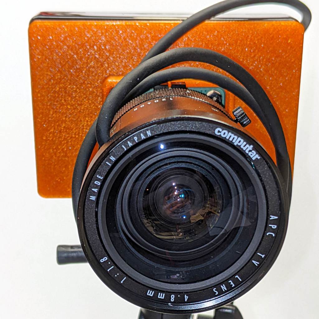
The Big Box o’ Optics disgorged an ancient new-in-box Computar 4.8 mm lens, originally intended for a TV camera, with a C mount perfectly suited for the Raspberry Pi HQ camera:

Because it’s a video lens, it includes an aperture driver expecting a video signal from the camera through a standard connector:

The datasheet tucked into the box (!) says it expects 8 to 16 V DC on the red wire (with black common) and video on white:
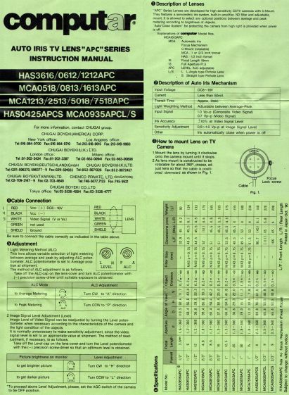
Fortunately, applying 5 V to red and leaving white unconnected opens the aperture all the way. Presumably, the circuitry thinks it’s looking at a really dark scene and isn’t fussy about the missing sync pulses.
Rather than attempt to find / harvest a matching camera connector, the cord now terminates in a JST plug, with the matching socket hot-melt glued to the Raspberry Pi case:

The Pi has +5 V and ground on the rightmost end of its connector, so the Computar lens will be jammed fully open.
I gave it something to look at:

With the orange back plate about 150 mm from the RPi, the 4.8 mm lens delivers this scene:

The focus is on the shutdown / startup button just to the right of the heatsink, so the depth of field is maybe 25 mm front-to-back.
For comparison, the official 16 mm lens stopped down to f/8 has a tighter view with good depth of field:

It’d be nice to have a variable aperture, but it’s probably not worth the effort.

The green-LED discrete LM3909 is still flashing, even with its AA NiMH cells burned down to 1.15 V:
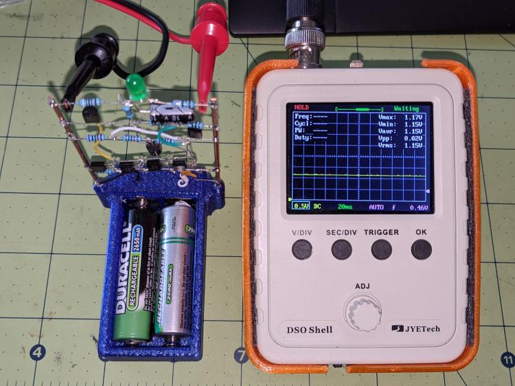
If the truth be known, one of the cells is now reverse-charged to 200 mV, so that’s a bit beyond as low as it can go.
The flash period has stretched to 8.7 s:

The circuit boosts the battery by 800 mV to put 1.94 V across the green LED at the start of each flash:

Admittedly, the LED isn’t particularly bright at 2.8 mA:

But it’s still flashing!
Swapping the cells into the LM3909 with a blue LED doesn’t produce any blinking, which is about what the earlier tests showed.
