Ed Nisley's Blog: Shop notes, electronics, firmware, machinery, 3D printing, laser cuttery, and curiosities. Contents: 100% human thinking, 0% AI slop.
Having replaced our disintegrating Brita pitcher a few years ago, I finally got around to opening a used filter to see what’s inside. Start by cutting off the flexible rim (intended as a seal against the pitcher) to reveal the joint, then pry the lid off:
Brita pitcher filter – opening
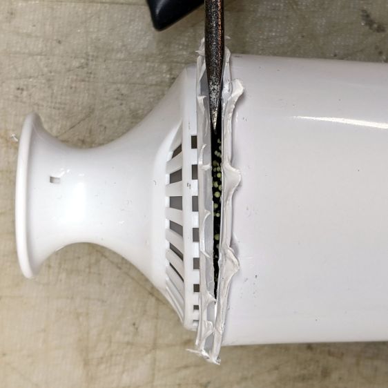
Stand it upright before getting the lid off, because the filter contains a zillion charcoal granules and two zillion ion-exchange resin beads:
Brita pitcher filter – granules
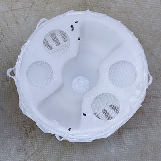
The inside of the lid has mesh screens to keep the innards in place while distributing the raw water:
Brita pitcher filter – lid
Similarly, mesh on the bottom drains let the filtered water out:
Brita pitcher filter – emptied
No surprises, but now we all know what’s in there.
For reasons not relevant here, I sent the Beckman DM73 to a good home in Europe. Having some experience with the brutality applied to innocent packages by various package-delivery organizations, I filled a Priority Mail Flat Rate Small Box with a solid block of corrugated cardboard:
DM73 – cardboard armor
One inner layer has a cutout for the manual:
DM73 – Operator Manual package
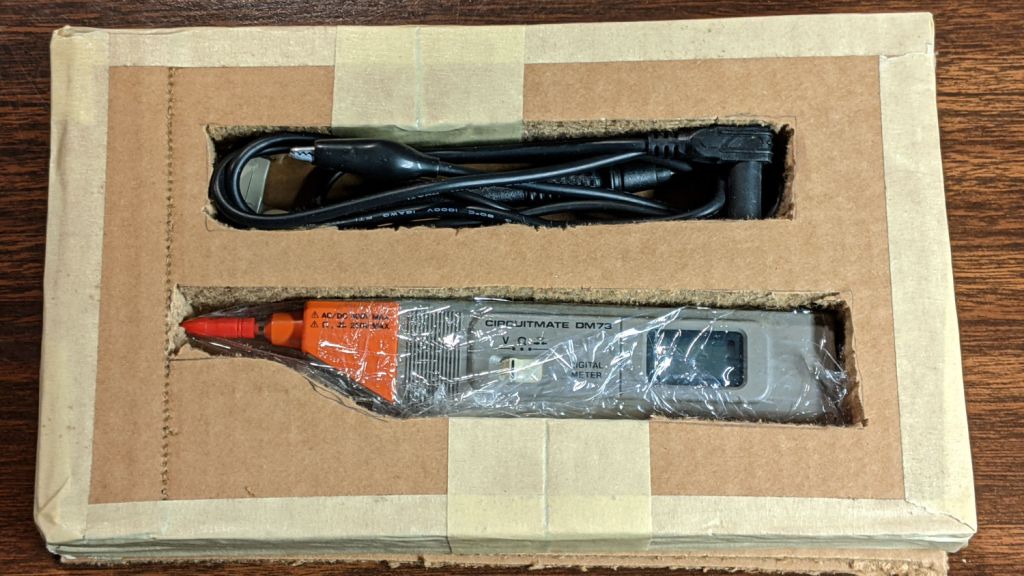
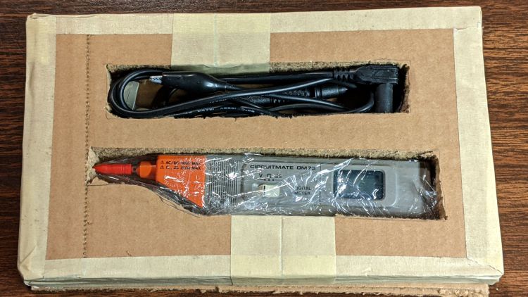
The meter and its leads tuck into form-fitting cutouts:
Beckman DM73 – cardboard packing
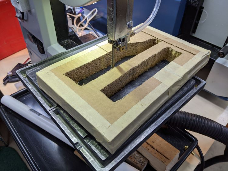
I bandsawed the cutouts from a block with enough layers for some space on the top and bottom:
DM73 – bandsawing cardboard package
After mulling that layout overnight, I made a similar block with the saw cuts on diagonally opposite corners, so pressure on the center of the edges won’t collapse the unsupported sides. A slightly larger meter cutout allowed a wrap of closed-cell foam sheet that likely doesn’t make any difference at all.
With everything in place, the box had just enough space for a pair of plastic sheets to better distribute any top & bottom impacts.
I won’t know how the armor performed for a few weeks, but it’s definitely the best packaging idea I’ve had so far.
Update: After nearly two weeks, the package arrived undamaged and the meter was in fine shape. Whew!
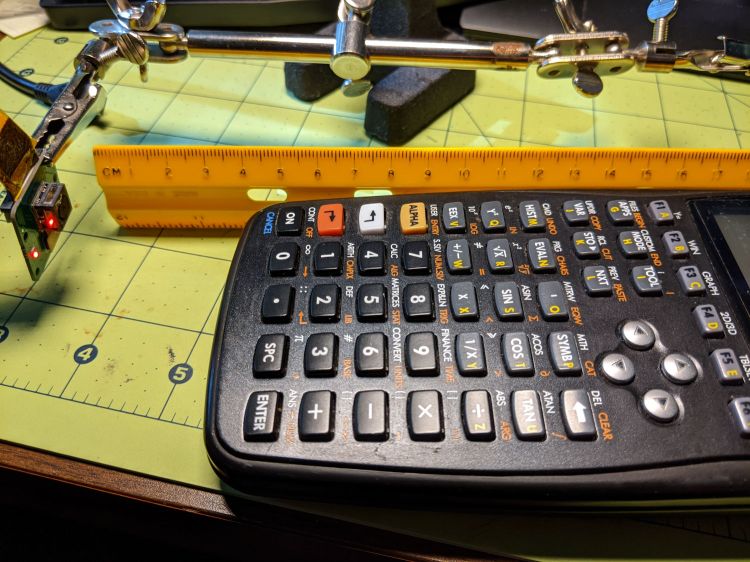
According to the Arducam doc, their Motorized Focus Camera has a 54°×41° field of view, (roughly) equivalent to an old-school wide(-ish) angle 35 mm lens on a 35 mm still camera. For my simple purposes, the camera will be focused on objects within maybe 200 mm:
Arducam Motorized Focus Camera – desktop test range
The numeric keys are 6.36 mm = ¼ inch tall, the function keys are 5.3 mm tall, and the rows are 10 to 11 mm apart.
The focusing equation converting distance to lens DAC values depends critically on my crude measurements, so the focus distance accuracy isn’t spot on. Bonus: there’s plenty of room for discussion about where the zero origin should be, but given the tune-for-best-picture nature of focusing, it’s good enough.
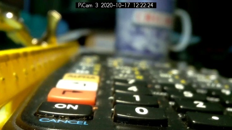
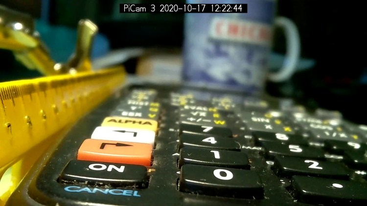
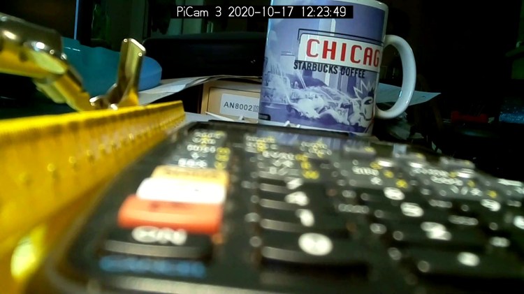
I set the CANCEL legend at 50 mm and it’s in good focus with the lens set to that distance:
Arducam Motorized Focus Camera – 50 mm
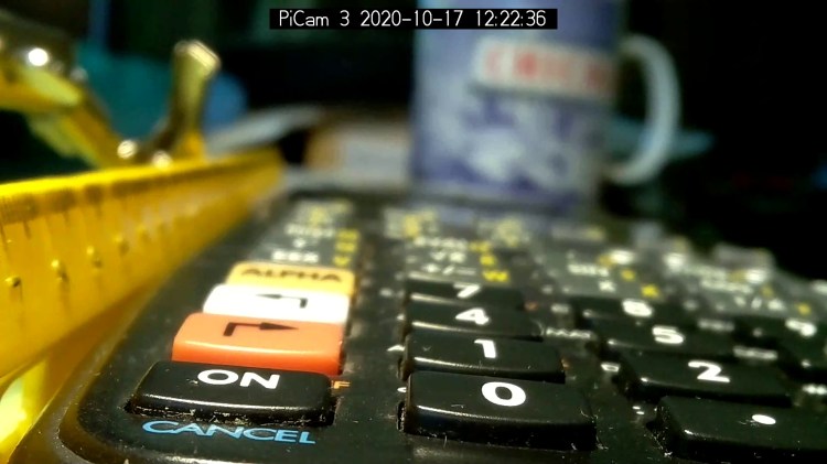
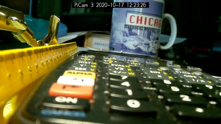
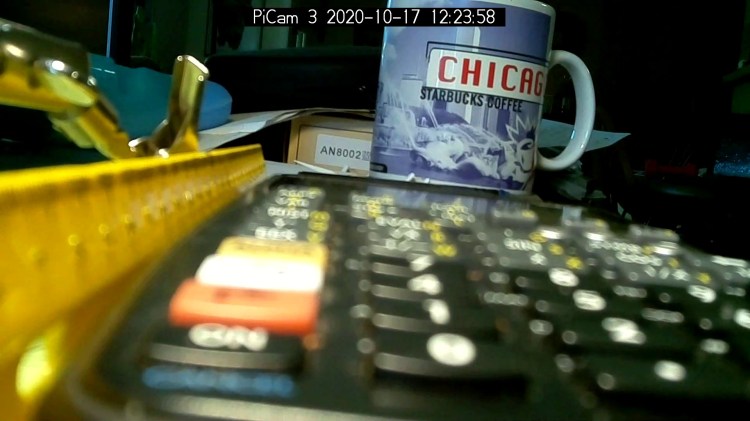
Focusing at 55 mm sharpens the ON key legend, while the CANCEL legend remains reasonably crisp:
Arducam Motorized Focus Camera – 55 mm
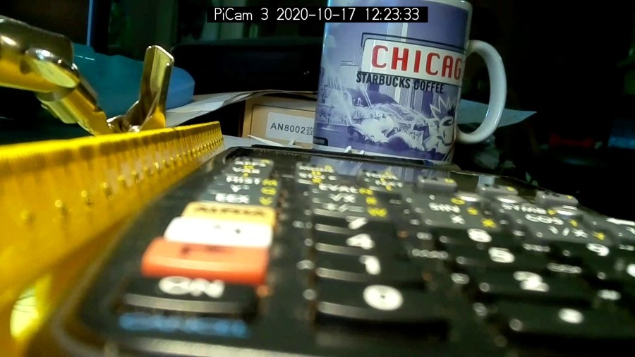
Adding another 5 mm to focus at 60 mm near the front of the second row shows the DoF is maybe 15 mm total:
Arducam Motorized Focus Camera – 60 mm
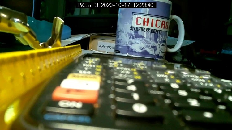
Focusing at 65 mm, near the middle of the second row, softens the first and fourth rows. Both of the middle two rows seem OK, making the DoF about 20 mm overall:
Arducam Motorized Focus Camera – 65 mm
Jumping to 100 mm, near the top of the first function row:
Arducam Motorized Focus Camera – 100 mm
At 150 mm, about the top of the far row just under the display:
Arducam Motorized Focus Camera – 150 mm
I think 200 mm may be the far limit of useful detail for a 5 MP camera:
Arducam Motorized Focus Camera – 200 mm
At 300 mm the DoF includes the mug at 600 mm, but the calculator keyboard is uselessly fuzzy:
Arducam Motorized Focus Camera – 300 mm
At 500 mm, the mug becomes as crisp as it’ll get and the text on the box at 750 mm is entirely legible:
Arducam Motorized Focus Camera – 500 mm
At 1000 mm, which is basically the edge of the desk all this junk sits atop, the mug and text become slightly fuzzy, so the DoF doesn’t quite reach them:
Arducam Motorized Focus Camera – 1000 mm
I limited the focus range to 1500 mm, which doesn’t much change the results:
Arducam Motorized Focus Camera – 1500 mm
I could focus-stack a set of still images along the entire range to get one of those unnatural everything-in-focus pictures.
Arducam Motorized Focus Camera – desktop test range
Run the test code:
# Simpleminded focusing test for
#  Arducam Motorized Focus Camera
# Gets events through evdev from rotary encoder knob

# Ed Nisley - KE4ZNU
# 2020-10-20

import sys
import math
import evdev
import smbus

# useful functions

def DAC_from_distance(dist):
    return math.trunc(256*(10.8 + 2180/dist))

# write DAC word to camera I2C bus device
#  and ignore the omnipresent error return

def write_lens_DAC(bus,addr,val):
    done = False
    while not done:
        try:
            bus.write_word_data(addr,val >> 8,val & 0xff)
        except OSError as e:
            if e.errno == 121:
#                print('OS remote error ignored')
                done = True
        except:
            print(sys.exc_info()[0],sys.exc_info()[1])
        else:
            print('Write with no error!')
            done = True

# set up focus distances

closest = 50            # mm
farthest = 500
nominal = 100           # default focus distance

foci = [n for n in range(closest,nominal,5)] \
     + [n for n in range(nominal,250,10)]  \
     + [n for n in range(250,1501,25)]

# compute DAC equivalents for each distance

foci_DAC = list(map(DAC_from_distance,foci))

focus_index = foci.index(nominal)

# set up the I2C bus

f = smbus.SMBus(0)
lens = 0x0c

# set up the encoder device handler
# requires rotary-encoder dtoverlay aimed at pins 20 & 21

d = evdev.InputDevice('/dev/input/by-path/platform-rotary@14-event')
print('Rotary encoder device: {}'.format(d.name))

# set initial focus

write_lens_DAC(f,lens,foci_DAC[focus_index])

# fetch I2C events and update the focus forever

for e in d.read_loop():
#    print('Event: {}'.format(e))

    if e.type == evdev.ecodes.EV_REL:
#        print('Rel: {}'.format(e.value))

        if (e.value > 0 and focus_index < len(foci) - 1) or (e.value < 0 and focus_index > 0):
            focus_index += e.value

        dist = foci[focus_index]
        dac = foci_DAC[focus_index]

        print('Distance: {:4d} mm DAC: {:5d} {:04x} i: {:3d}'.format(dist,dac,dac,focus_index))

        write_lens_DAC(f,lens,dac)
Because the knob produces increments of ±1, the code accumulates them into an index for the foci & foci_DAC lists, then sends the corresponding entry from the latter to the lens on every rotary encoder event.
And then It Just Works!
The camera powers up with the lens focused at infinity (or slightly beyond), but setting it to 100 mm seems more useful:
Arducam Motorized Focus Camera – 100 mm
Turning the knob counterclockwise runs the focus inward to 50 mm:
Arducam Motorized Focus Camera – 50 mm
Turning it clockwise cranks it outward to 1500 mm:
Arducam Motorized Focus Camera – 1500 mm
The mug is about 300 mm away, so the depth of field extends from there to infinity (and beyond).
It needs more work, but now it has excellent upside potential!
Name:   gpio-key
Info:   This is a generic overlay for activating GPIO keypresses using
        the gpio-keys library and this dtoverlay. Multiple keys can be
        set up using multiple calls to the overlay for configuring
        additional buttons or joysticks. You can see available keycodes
        at https://github.com/torvalds/linux/blob/v4.12/include/uapi/
        linux/input-event-codes.h#L64
Load:   dtoverlay=gpio-key,<param>=<val>
Params: gpio                    GPIO pin to trigger on (default 3)
        active_low              When this is 1 (active low), a falling
                                edge generates a key down event and a
                                rising edge generates a key up event.
                                When this is 0 (active high), this is
                                reversed. The default is 1 (active low)
        gpio_pull               Desired pull-up/down state (off, down, up)
                                Default is "up". Note that the default pin
                                (GPIO3) has an external pullup
        label                   Set a label for the key
        keycode                 Set the key code for the button
Snuggle the button configuration next to the encoder in /boot/config.txt:
I haven’t yet discovered where the label text appears, because I picked a keycode defining the button as the decimal point key on a numeric keypad. Perhaps one could create a unique key from whole cloth, but that’s in the nature of fine tuning. In any event, pressing / releasing the button produces key-down / key-up events just like you’d get from a real keyboard.
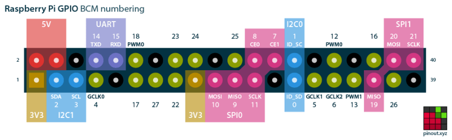
The four pins required for the encoder + switch make a tidy block at the right (in this view, left as shown above) end of the RPi’s header:
Raspberry Pi pinout
If you needed the SPI1 hardware, you’d pick different pins.
Reboot that sucker and another input device appears:
ll /dev/input/by-path/
total 0
lrwxrwxrwx 1 root root 9 Oct 18 10:00 platform-button@1a-event -> ../event0
lrwxrwxrwx 1 root root 9 Oct 18 10:00 platform-rotary@14-event -> ../event2
lrwxrwxrwx 1 root root 9 Oct 18 10:00 platform-soc:shutdown_button-event -> ../event1
As with the encoder device, the button device name includes the hex equivalent of the pin number: 26 decimal = 0x1a.
Run some code:
# Keypress from Raspberry Pi GPIO pin using evdev
# Add to /boot/config.txt
#  dtoverlay=gpio-key,gpio=26,keycode=83,label="KNOB"

import evdev

b = evdev.InputDevice('/dev/input/by-path/platform-button@1a-event')
print('Button device: {}'.format(b.name))

print(' caps: {}'.format(b.capabilities(verbose=True)))
print(' fd: {}'.format(b.fd))

for e in b.read_loop():
    print('Event: {}'.format(e))
    if e.type == evdev.ecodes.EV_KEY:
        print('Key {}: {}'.format(e.code,e.value))
Which produces this output:
Button device: button@1a
caps: {('EV_SYN', 0): [('SYN_REPORT', 0), ('SYN_CONFIG', 1)], ('EV_KEY', 1): [('KEY_KPDOT', 83)]}
fd: 3
Event: event at 1603036309.683348, code 83, type 01, val 01
Key 83: 1
Event: event at 1603036309.683348, code 00, type 00, val 00
Event: event at 1603036310.003329, code 83, type 01, val 00
Key 83: 0
Event: event at 1603036310.003329, code 00, type 00, val 00
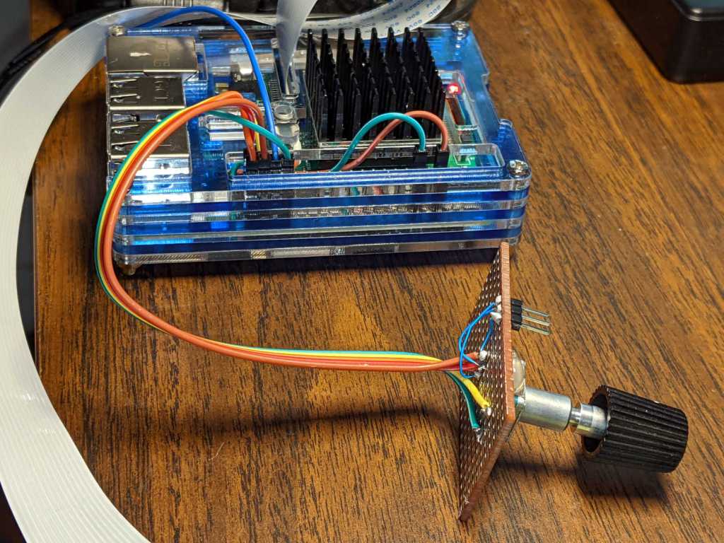
First, enhance the knob’s survivability & usability by sticking it on a perfboard scrap:
RPi rotary encoder – improved test fixture
Then find the doc in /boot/overlays/README:
Name: rotary-encoder
Info: Overlay for GPIO connected rotary encoder.
Load: dtoverlay=rotary-encoder,
=
Params: pin_a GPIO connected to rotary encoder channel A
(default 4).
pin_b GPIO connected to rotary encoder channel B
(default 17).
relative_axis register a relative axis rather than an
absolute one. Relative axis will only
generate +1/-1 events on the input device,
hence no steps need to be passed.
linux_axis the input subsystem axis to map to this
rotary encoder. Defaults to 0 (ABS_X / REL_X)
rollover Automatic rollover when the rotary value
becomes greater than the specified steps or
smaller than 0. For absolute axis only.
steps-per-period Number of steps (stable states) per period.
The values have the following meaning:
1: Full-period mode (default)
2: Half-period mode
4: Quarter-period mode
steps Number of steps in a full turnaround of the
encoder. Only relevant for absolute axis.
Defaults to 24 which is a typical value for
such devices.
wakeup Boolean, rotary encoder can wake up the
system.
encoding String, the method used to encode steps.
Supported are "gray" (the default and more
common) and "binary".
Add a line to /boot/config.txt to configure the hardware:
The overlay enables the pullup resistors by default, so the encoder just pulls the pins to common. Swapping the pins reverses the sign of the increments, which may be easier than swapping the connector after you have it all wired up.
The steps-per-period matches the encoder in hand, which has 30 detents per full turn; the default value of 1 step/period resulted in every other detent doing nothing. A relative axis produces increments of +1 and -1, rather than the accumulated value useful for an absolute encoder with hard physical stops.
Reboot that sucker and an event device pops up:
ll /dev/input
total 0
drwxr-xr-x 2 root root 80 Oct 18 07:46 by-path
crw-rw---- 1 root input 13, 64 Oct 18 07:46 event0
crw-rw---- 1 root input 13, 65 Oct 18 07:46 event1
crw-rw---- 1 root input 13, 63 Oct 18 07:46 mice
I’m unable to find the udev rule (or whatever) creating those aliases and, as with all udev trickery, the device’s numeric suffix is not deterministic. The only way you (well, I) can tell which device is the encoder and which is the power-off button is through their aliases:
ll /dev/input/by-path/
total 0
lrwxrwxrwx 1 root root 9 Oct 18 07:46 platform-rotary@14-event -> ../event0
lrwxrwxrwx 1 root root 9 Oct 18 07:46 platform-soc:shutdown_button-event -> ../event1
The X axis of the mice device might report the same values, but calling a rotary encoder a mouse seems fraught with technical debt.
The name uses the hex equivalent of the A channel pin number (20 = 0x14), so swapping the pins in the configuration will change the device name; rewiring the connector may be easier.
Using the alias means you always get the correct device:
# Rotary encoder using evdev
# Add to /boot/config.txt
#  dtoverlay=rotary-encoder,pin_a=20,pin_b=21,relative_axis=1,steps-per-period=2
# Tweak pins and steps to match the encoder

import evdev

d = evdev.InputDevice('/dev/input/by-path/platform-rotary@14-event')
print('Rotary encoder device: {}'.format(d.name))

position = 0

for e in d.read_loop():
    print('Event: {}'.format(e))
    if e.type == evdev.ecodes.EV_REL:
        position += e.value
        print('Position: {}'.format(position))
Which should produce output along these lines:
Rotary encoder device: rotary@14
Event: event at 1603019654.750255, code 00, type 02, val 01
Position: 1
Event: event at 1603019654.750255, code 00, type 00, val 00
Event: event at 1603019654.806492, code 00, type 02, val 01
Position: 2
Event: event at 1603019654.806492, code 00, type 00, val 00
Event: event at 1603019654.949199, code 00, type 02, val 01
Position: 3
Event: event at 1603019654.949199, code 00, type 00, val 00
Event: event at 1603019655.423506, code 00, type 02, val -1
Position: 2
Event: event at 1603019655.423506, code 00, type 00, val 00
Event: event at 1603019655.493140, code 00, type 02, val -1
Position: 1
Event: event at 1603019655.493140, code 00, type 00, val 00
Event: event at 1603019655.624685, code 00, type 02, val -1
Position: 0
Event: event at 1603019655.624685, code 00, type 00, val 00
Event: event at 1603019657.652883, code 00, type 02, val -1
Position: -1
Event: event at 1603019657.652883, code 00, type 00, val 00
Event: event at 1603019657.718956, code 00, type 02, val -1
Position: -2
Event: event at 1603019657.718956, code 00, type 00, val 00
Event: event at 1603019657.880569, code 00, type 02, val -1
Position: -3
Event: event at 1603019657.880569, code 00, type 00, val 00
The type 00 events are synchronization points, which might be more useful with more complex devices.
Because the events happen outside the kernel scheduler’s notice, you (well, I) can now spin the knob as fast as possible and the machinery will generate one increment per transition, so the accumulated position changes smoothly.