Ed Nisley's Blog: Shop notes, electronics, firmware, machinery, 3D printing, laser cuttery, and curiosities. Contents: 100% human thinking, 0% AI slop.
We buy olive oil in large bottles, then fill smaller bottles for easier handling. The caps on those bottles were never meant to last as long as we keep them and the thin, deeply drawn aluminum tends to crack after a while.
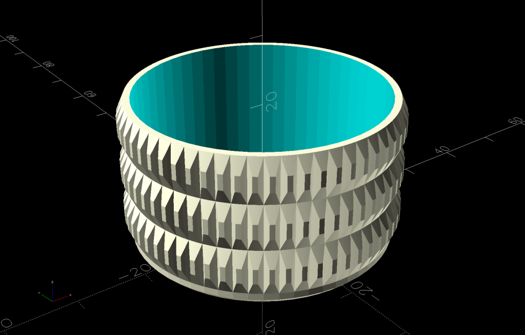
So I conjured a cap cover from the vasty digital deep:
Olive Oil Cap – solid model
Which looks exactly like you’d expect when printed in black PETG:
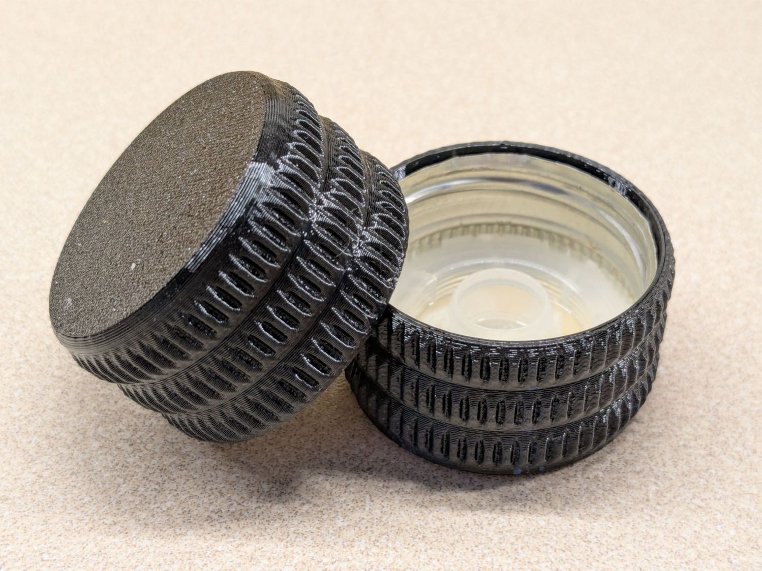
Olive oil bottle cap – details
You can see the raggedy edge of the original cap just inside the cover’s rim. A snippet of double-sided tape holds the cover in place, after de-oiling the cap with alcohol.
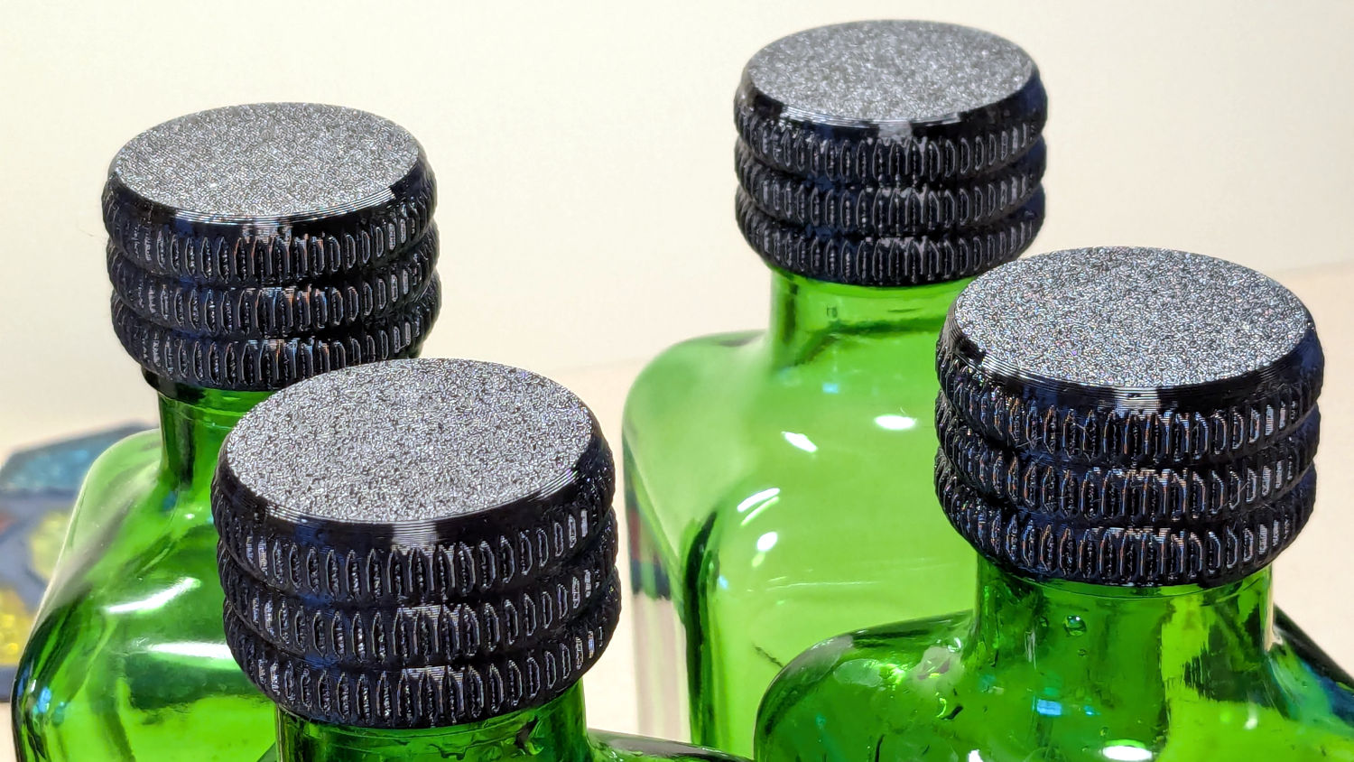
Having gotten one to fit, I made enough for All The Bottles:
Olive oil bottle cap – installed
Only two of those see regular service: one in use and another filled when the first is nearly empty. The remaining pair huddle in the back of the shelf against future need.
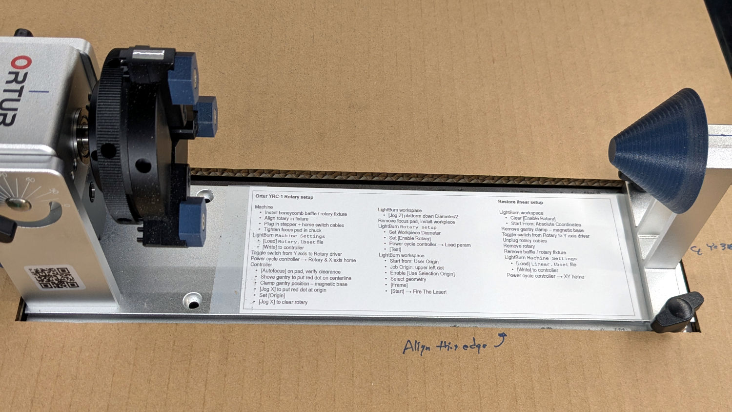
Always disable the rotary’s stepper driver before connecting or disconnecting its cable.
The Ortur YRC-1 rotary has a pulley ratio of 1:3, so the step/rev value is three times the DIP switch setting on the stepper driver. For this setup, 1600 → 4800 step/rev.
The honeycomb frame is a parallelogram, not a rectangle. I align the cardboard baffle / fixture to the bottom edge of the frame and the rotary to the bottom edge of the fixture opening, but your machine will be different. The angular alignment may not be off by enough to matter, but consistency is a virtue.
The Rotary.lbset and Linear.lbset files live on a file server with daily backups. Such backups will come in handy when you inadvertently overwrite one of those files with the other one. Trust me on this.
The Rotary.lbset file does not have Rotary Mode enabled, because the KT332N does not home the Y axis in that mode. If your rotary lacks a home switch, then it doesn’t matter and you’re on your own.
The KT332N controller has a [Reset] button that allegedly does a power-on reset and reloads all the changed Machine Settings. This sometimes does not work as expected: power-cycling the controller is the only way to be sure.
The autofocus operation must hit the focus pad, which can be ensured by positioning the pen near the pad, jogging the platform a few millimeters under the pen, tweaking X and the gantry while peering down parallel to the pen, then doing the autofocus.
The focus pad has a crosshair clearing the chonky Ortur 3-step jaws, but I set the controller’s [Origin] at the foot of the pad’s base for more elbow room.
The Z axis distance field in LightBurn’s Move window does not accept formulas, so you must divide the workpiece diameter by two. Using a focus stick to verify the ensuing nozzle-to-workpiece distance is a Good Idea™.
The LightBurn Job Origin dot must be on the top row, because the KT332N does not go into regions with negative coordinates. With the chuck on the left and the [Origin] just to its right, the upper left dot locks the LightBurn selection to the physical limits.
Selecting [Use Selection Origin] puts the Job Origin at the upper left (per the dot) of whatever you’ve selected, not everything on the LightBurn workspace. [User Origin] then locks the selection to the [Origin] set on the controller.
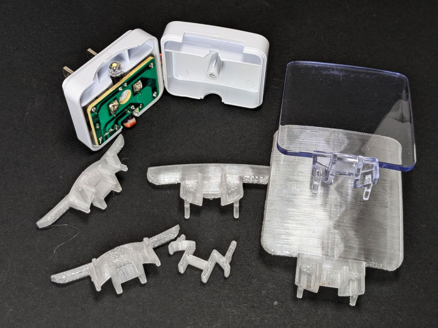
Our house came with several single-LED night lights featuring a transparent light guide / reflector:
Nightlight light guide – original
The plate had snapped off one of them and, being me, I wondered if I could replace it with something similar.
Years passed.
Obviously, this must be made from a transparent substance, which 3D printed things are not, but after some fiddling with parameters I thought the result might be informative.
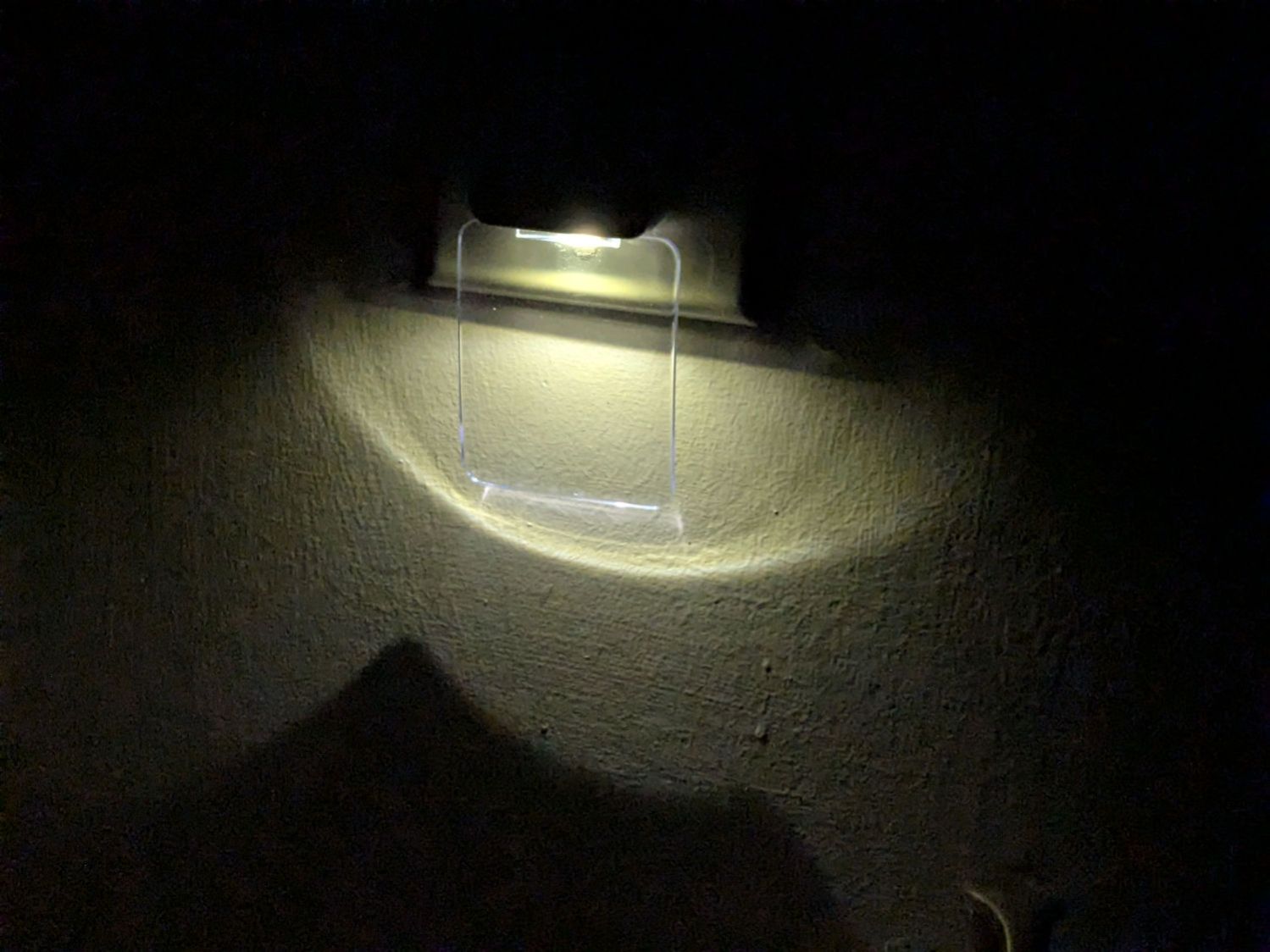
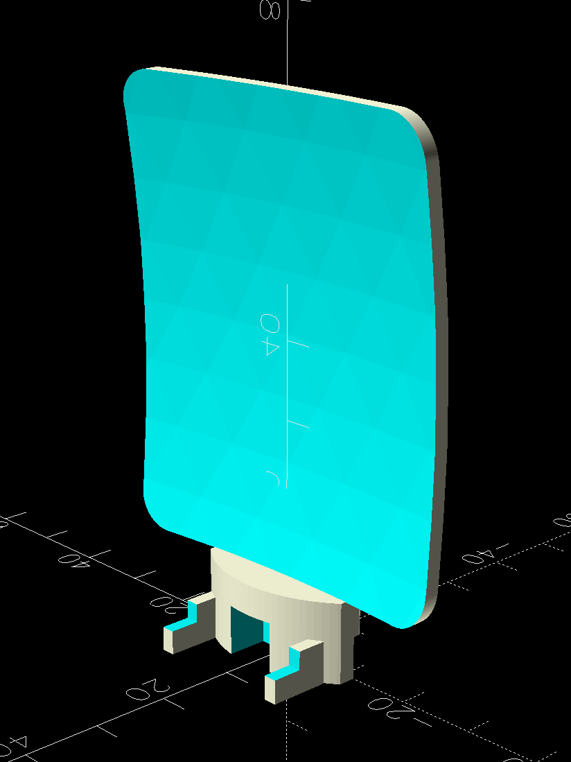
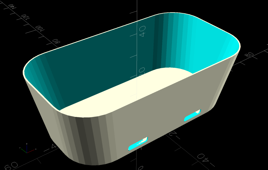
The guide plate is a section of a spherical surface, here approximated by a BOSL2 spheroid():
Nightlight light guide – view side – solid model
The original is 3 mm thick, but 2 mm worked out better for my purposes by reducing the amount of infill:
Nightlight light guide – wall side – solid model
The intricate base latches into the lamp’s plastic case:
Nightlight light guide – base – solid model
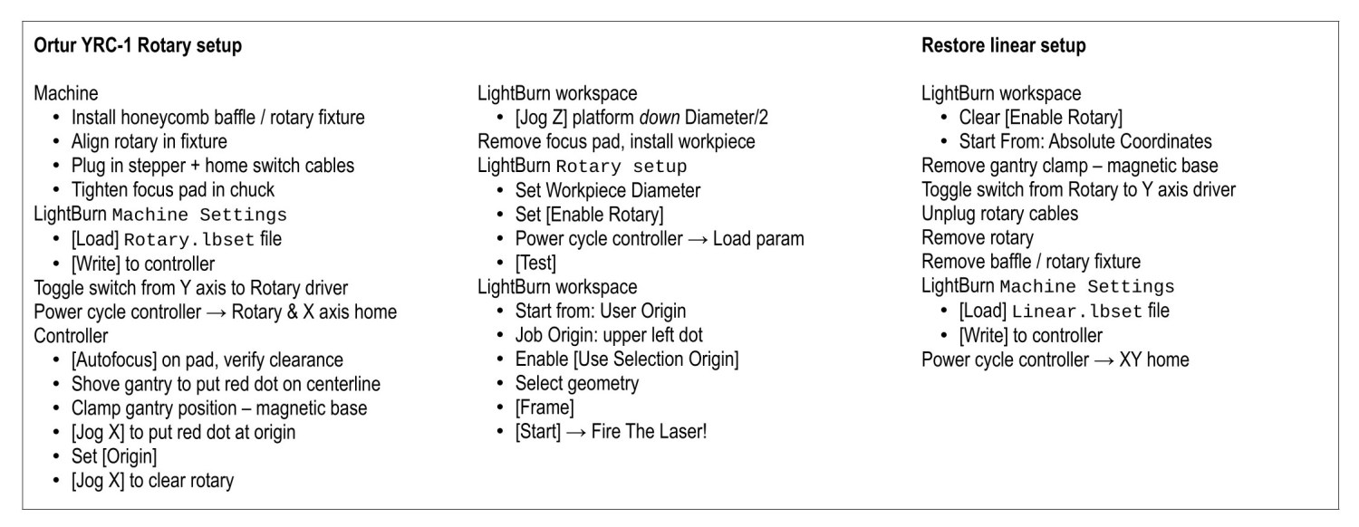
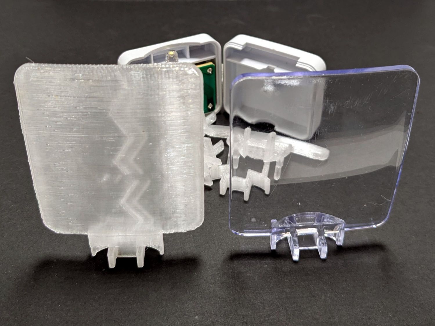
The result is, at best, translucent, because it’s definitely not transparent:
Nightlight light guide – translucent vs transparent
The zigzag pattern seems to come from the icosohedral approximation to the sphere, because it follows the surface tesselation.
Getting the base shape right required several iterations, each printed with the model cut off just above the bottom of the guide plate:
Nightlight light guide – test pieces
The first two attempts needed attention from a flush cutting pliers before fitting into the case, but they don’t call it rapid prototyping for nothin’.
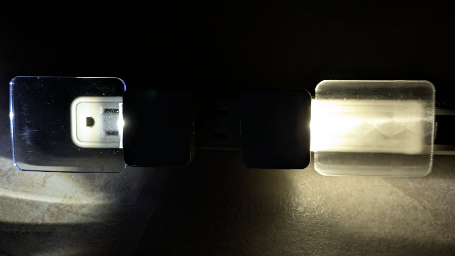
The original and replacement plugged into an outlet strip:
Nightlight light guide – original vs printed on outlet strip
While you can see the vague outline of the strip behind the printed light guide, it’s definitely lacking in detail:
Nightlight light guide – outlet strip detail
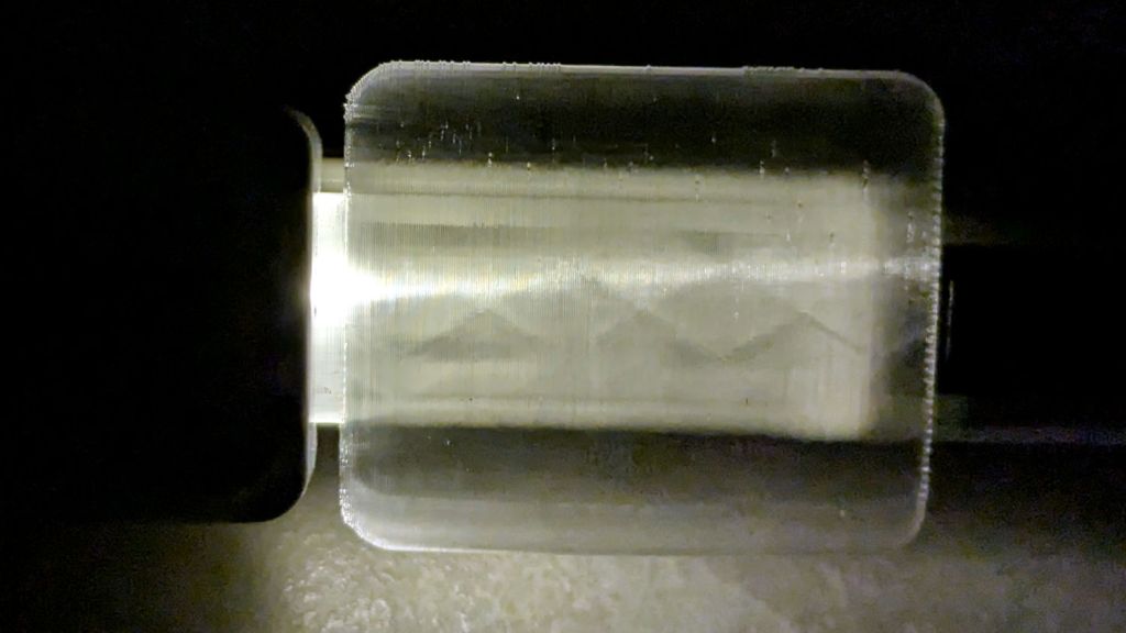
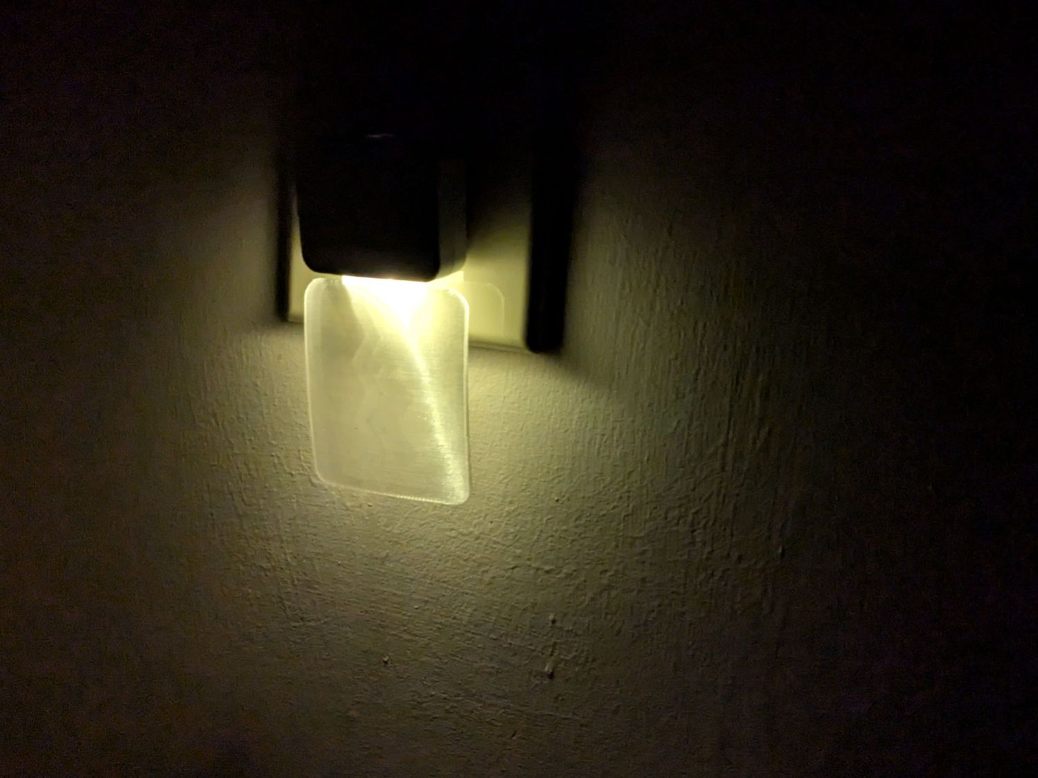
The striations throw more light into the room than the original:
Nightlight light guide – printed
Fiddling with the 3D printing parameters might make it more transparent, but it’s going back into the box it came from after giving me a better idea of which parameters to tweak the next time around.
This file contains hidden or bidirectional Unicode text that may be interpreted or compiled differently than what appears below. To review, open the file in an editor that reveals hidden Unicode characters.
Learn more about bidirectional Unicode characters
A SquidWrench meeting discussion about printing transparent objects prompted me to conjure a soap dish from the vasty digital deep:
Shower Soap Dish – solid model
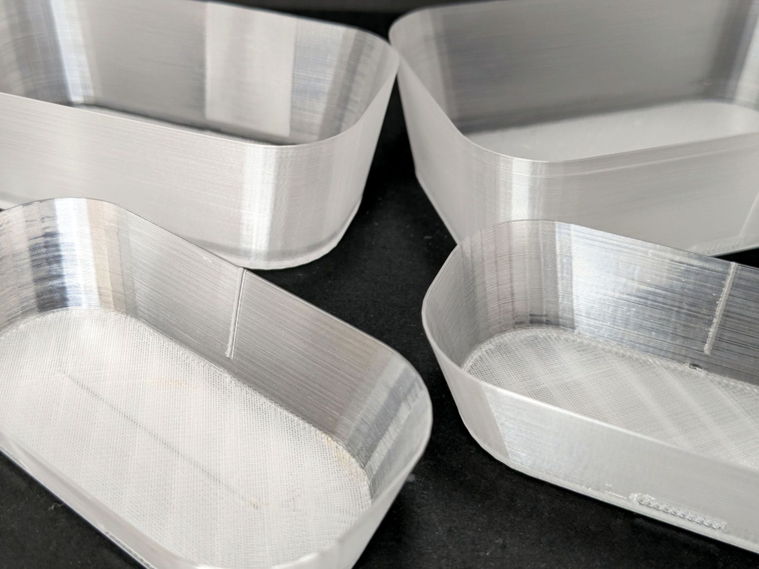
They’re all done in “natural” PETG with sufficient variations in speed, temperature, extrusion multiplier, and fill pattern to stock the shower & tub:
Translucent soap dishes
The single-thread sidewalls came out reasonably translucent in all the variations, but the baseplate remained stubbornly white-ish, even at 20 mm/s and 250 °C with 100% infill. The seams where the extruder retracts and lifts to the next layer remain conspicuous, with a scarf joint forming the white slab in the left-rear dish.
Quite a while ago, I’d considered making soap dishes with shattered-glass bottoms, but came to my senses. These have some key advantages:
Exactly the right size for narrow shower shelves
Light enough to not damage anything when it inevitably falls off
Reasonably unbreakable when that happens
Easily replaced
They’re also test pieces for the whole transparency thing, so it’s all good.
This file contains hidden or bidirectional Unicode text that may be interpreted or compiled differently than what appears below. To review, open the file in an editor that reveals hidden Unicode characters.
Learn more about bidirectional Unicode characters
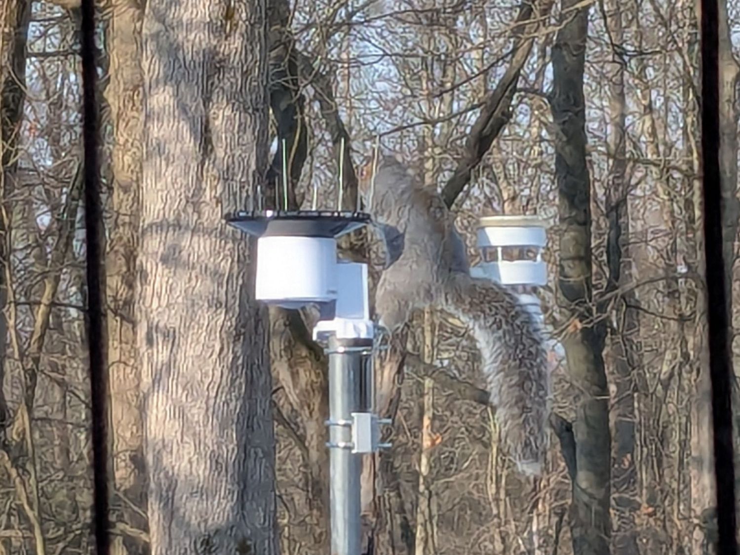
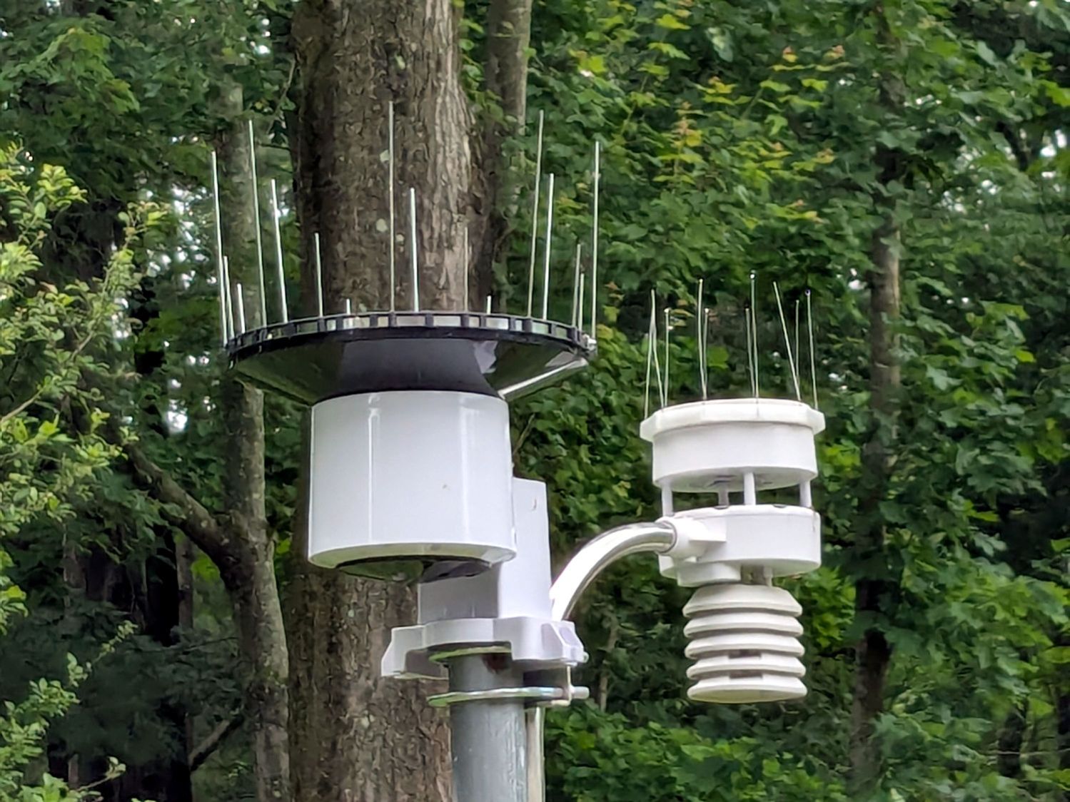
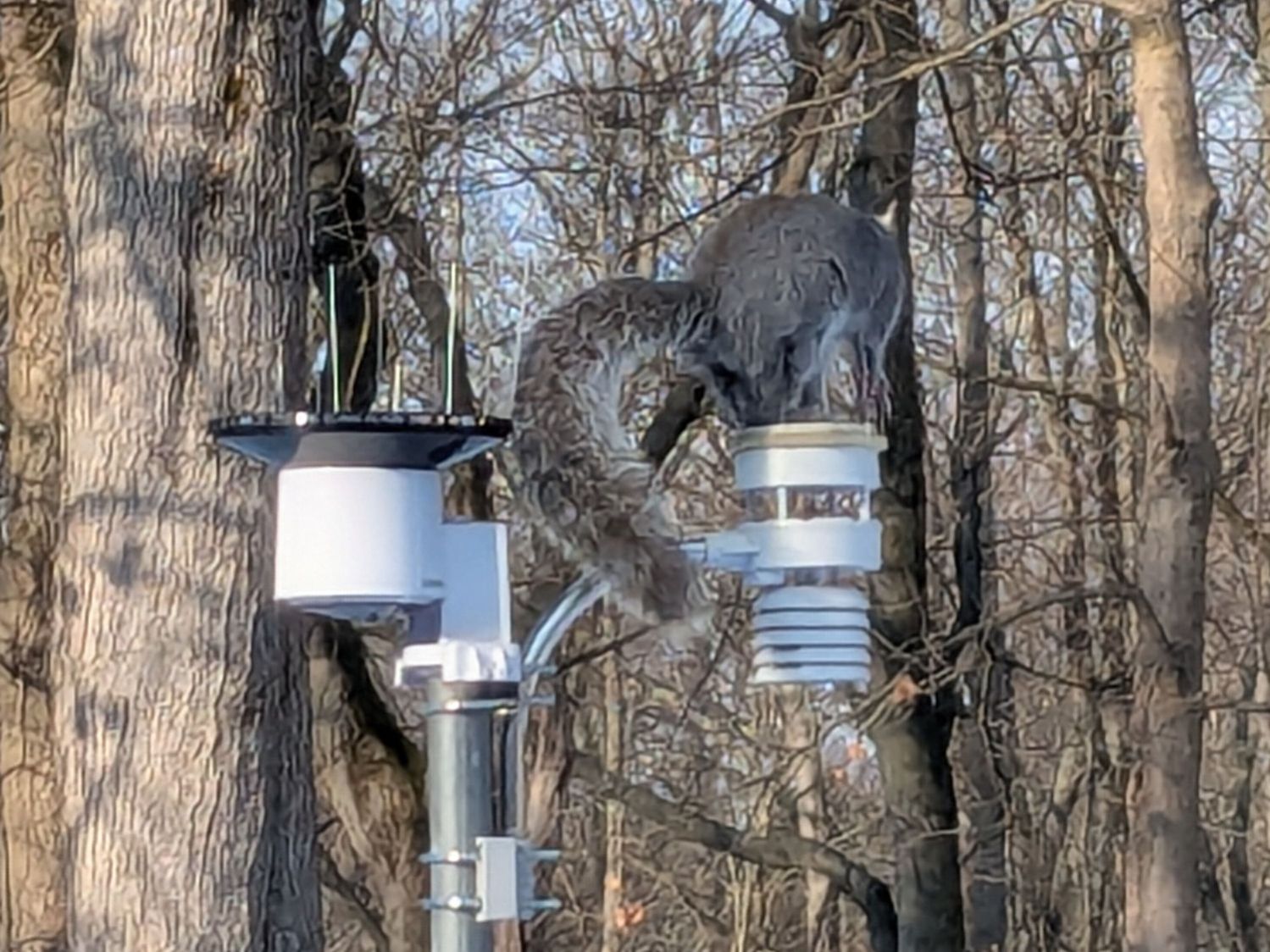
Chickadees can perch between the wires and squirrels apparently just ignore the sharp ends:
Squirrel on WS-5000 Anemometer spikes
No matter how hard that squirrel looked, there were no nuts to be found anywhere in that tree. Moments later it ran down the pole and loped across the yard to forage under the seed feeder.
The terrible picture quality comes from a Pixel 6a phone camera zoomed all the way tight. I want an optical telephoto lens built into the phone, but those phones seem intended to reduce the risks of having severe wallet overpressure.
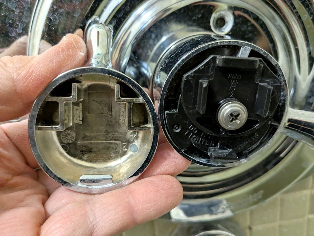
As a reminder for the next time in this rodeo, the latches holding the temperature adjustment knob on the Delta 17 Series dual-handle bath / shower faucet look like this:
Delta bath faucet cap latches
I am unable to apply enough force to the smooth edge of the knob opposite the handle to un-latch it, so I jammed a small prydriver into the gap and twisted enough to pop the latch, at the obvious risk of scarring the chrome plating.
A better approach would involve a plastic prydriver intended for consumer electronics case cracking.
For the record:
Unlike the other bath faucets, this one has shutoff valves inside the wall
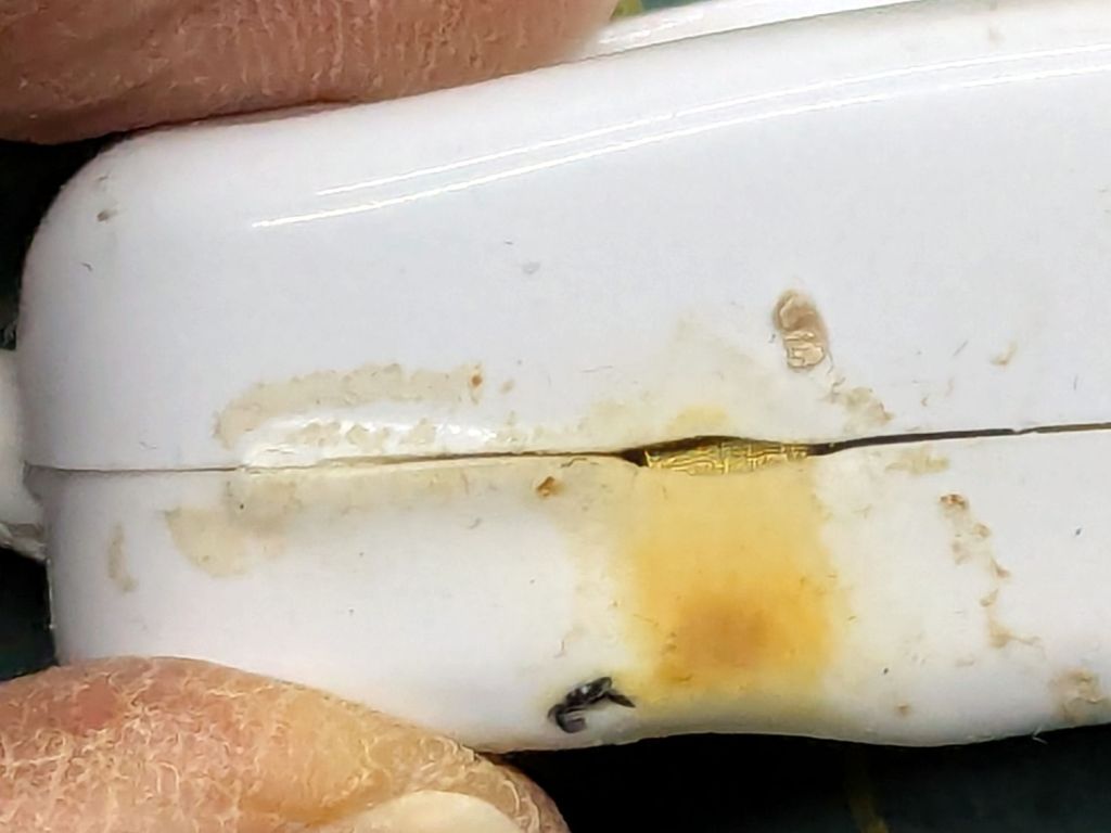
One of the inline switches I installed to replace the failed switches for the LED lights got unpleasantly warm enough to prompt an investigation:
Inline lamp switch – heat damage
Yeah, that is not a nominal outcome, particularly in light of the claimed “10 A 250 V” rating.
The overheated plastic pulled back enough to expose the terminal inside:
Inline lamp switch – visible terminal
There was a reason I’d wrapped those switches with known-good 3M electrical tape before deploying them.
That crimp connector took some heat and its screw looks even more unhappy:
Inline lamp switch – internal damage
It turned out the screw was an itsy too short to compress both the connector and the bent-metal conductor tab against the terminal block:
Inline lamp switch – misfit screw terminal
A 6 mm brass screw with a brass washer did a better job of compressing all parties into one conductive lump.
Although the switch now runs with the case at normal basement temperature, an allegedly UL listed replacement is on its way; it costs about five times more than that switch. If it behaves as it should, I’ll preemptively replace two other switches.