Ed Nisley's Blog: Shop notes, electronics, firmware, machinery, 3D printing, laser cuttery, and curiosities. Contents: 100% human thinking, 0% AI slop.
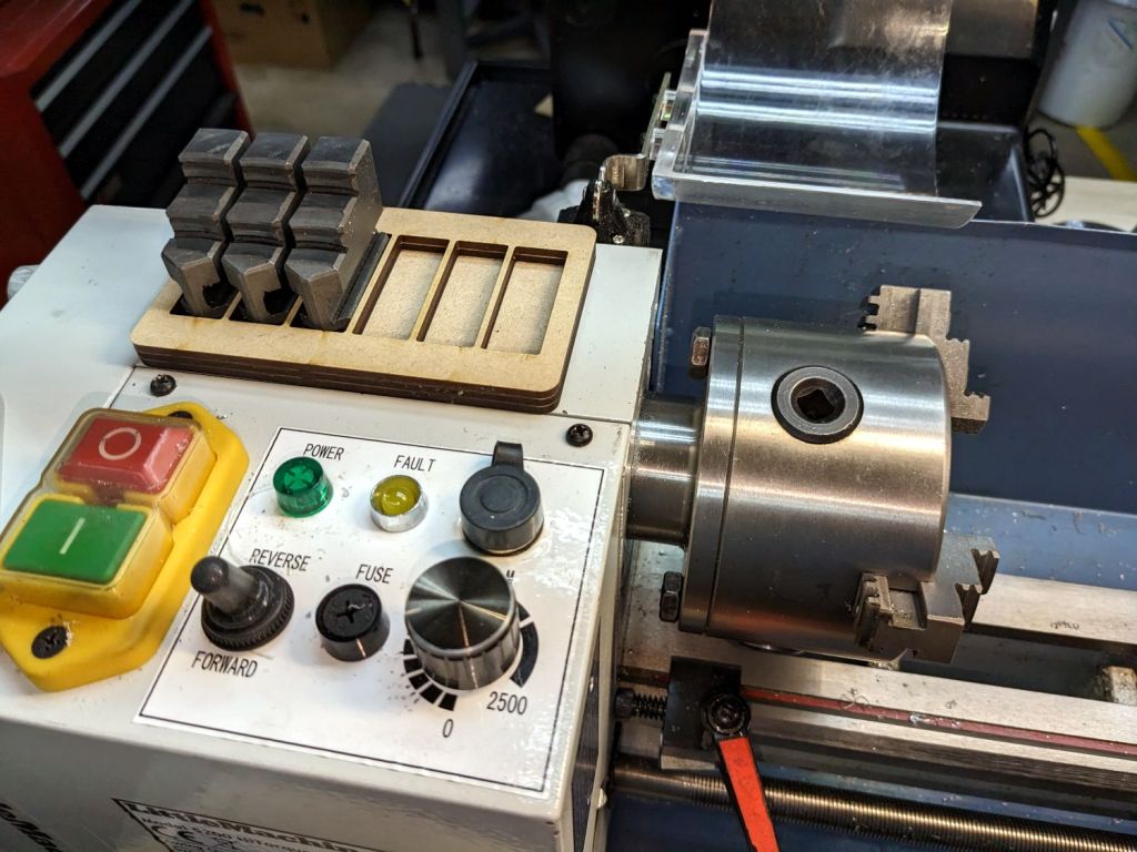
While swapping chuck jaws I realized I didn’t have to pile them on a shop rag atop the lathe headstock, no matter how neatly cut those rags might be:
Lathe chuck jaw holder – installed
It’s three layers of MDF cut to hold all six jaws from the 4 inch 3 jaw chuck, stuck together with wood glue.
You really need only four sockets: one empty for the jaw you just removed, then work your way around the chuck. But, hey, MDF is cheap and I usually remove all three at once anyway.
When it starts walking away, it’ll sprout silicone feet.
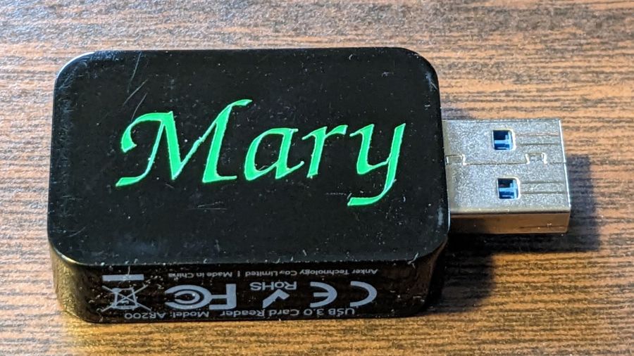
Mary’s ResMed AirSense 11 saves the data from every overnight breath she takes on an SD card, which she uploads to OSCAR once a week. I figured she needed an SD card to USB adapter / card reader of her very own:
The LightBurn layout is pretty much what you’d expect, with the letter inside the outline of the USB dingus on a tool layer to get the size right:
PU PSA Vinyl test – LB layout
The red layer is a “kiss cut” through the vinyl (remember: polyurethane) that leaves the backing paper mostly undamaged:
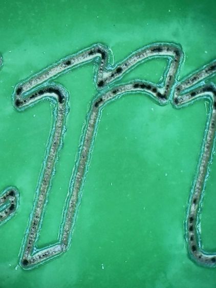
PU PSA Vinyl test – dot mode cut detail
The cut uses Dot Mode, with the laser firing at 10% power for 2 ms, spaced every 0.1 mm along the cut. I found 0.1 mm spacing produced a more-or-less continuous cut in the PETG sheet for the Tek Circuit Computer cursor hairline, but this picture shows it’s definitely running in pulsed mode. In any event, Dot Mode is the only way a 60 W CO₂ laser can make a kiss cut, as a normal vector cut can’t run fast enough to prevent cutting all the way through the backing paper, even at 10% power, around those letters.
The edges of the letters are slightly melted with a raised border, although they look pretty good if you’re not peering at them through a microscope.
I cut the rectangular outline with scissors, peeled the waste vinyl away, and weeded the ‘a’ with tweezers:
PU PSA Vinyl test – weeded
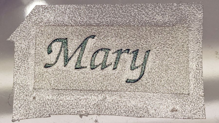
Stick a snippet of transfer tape on top:
PU PSA Vinyl test – transfer tape
In theory, the transfer tape sticks more firmly to the cut letters than the letters adhere to their backing paper, so peeling off the tape also peels the letters off the backing paper.
Which did not go well:
PU PSA Vinyl test – transfer tape – peeling
The two adhesions obviously require a delicate balance to work properly and I would be unsurprised to learn different transfer tapes behave differently on each type of vinyl sheet, with no way to know the results without trying every possible combination.
A few retries got the “r” back in position on the transfer tape, but a bit of kink remains in the “M”.
A third adhesion balance occurs between the transfer tape and the USB card reader, where the tape must stick to the letters slightly less than the letters stick to the reader. Burnishing the tape + letters to the reader encouraged the letters to stick and the tape pulled off without dislodging them.
We deemed the result good enough for the purpose and the process taught me a few lessons along the way. Next time, maybe it’ll work out better.
Reasonable people disagree as to the cause of the failure, but a replacement controller for the (new) Bafang motor I’m installing on my bike just arrived in the mail.
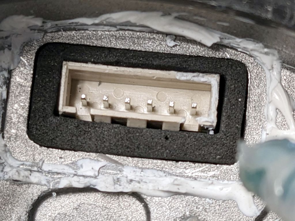
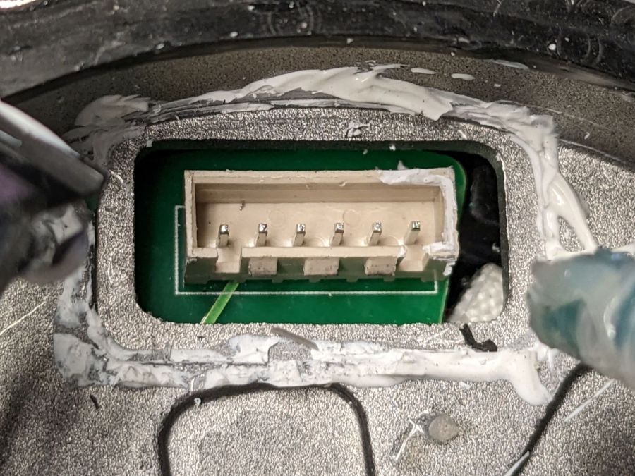
Disassembling the motor is straightforward, except for the part where you must excavate an internal plug from the silicone snot gluing it into place, eventually revealing its socket:
Bafang motor – interior gasket – connector
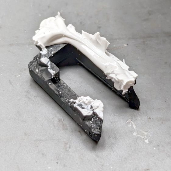
Regrettably, there seems no way to do that without destroying the dense closed-cell gasket around the connector:
Bafang motor – interior gasket – damaged original
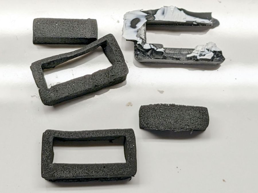
Equally regrettable: a replacement gasket wasn’t included with the replacement controller. Although I don’t have any of the specific foam, some marginally less dense foam from the Big Box o’ Padding seemed suitable for laser cuttery:
Bafang motor – interior gasket – iterations
The upper left prototype suggested a slightly larger rear bar that produced the gasket in front, which fit snugly:
Bafang motor – interior gasket – test fit
It lacks the latch cutout, but the foam is squishy and I expect to never touch it again.
A generous glob of hot melt glue holds everything in place:
Bafang motor – interior gasket – replacement glued
Although the usual Youtube videos show folks slathering RTV silicone caulk on these connectors, that’s a Very Bad Idea™, because RTV caulk releases acetic acid as it cures. That’s not a problem in the open-air siding-and-lumber environment the caulk was intended for, but sealing a glob of the stuff inside an enclosure will eventually corrode all of the electronics therein.
Cutting intricate doodads has become trivially easy: if you can draw it, you can pretty much cut it, just like that:
The big price displays at the Mobil station on the corner have always behaved oddly, but these replacements began failing within a week of their installation:
Mobil price sign – north face
That doesn’t look too bad, until you notice the number of dead LEDs in both red displays.
The south face is in worse shape:
Mobil price sign – south face
The green LEDs seem to be failing less rapidly than the reds, but I don’t hold out much hope for them.
The previous display had seven-segment digits made of smooth bars, rather than discrete LEDs. This one appeared after the segments failed at what must have been more than full brightness; the red LEDs were distracting by day and blinding by night.
Maybe they got the LEDs from the same folks selling traffic signals to NYS DOT? The signals around here continue to fail the same way, so I suppose DOT doesn’t replace them until somebody enough people complain.
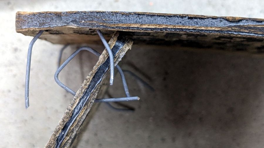
That’s eight months of weathering on MDF covered with indoor urethane sealant and it’s not as awful as I expected: the MDF didn’t actually disintegrate, it just collected some mold / mildew / crud.
A closer look:
Please Close The Gate – weathered MDF – detail
The black paint survived surprisingly well.
I hadn’t paid much any attention to the edges, so they got covered with random amounts of black paint and urethane. It seems that’s where the disintegration starts:
Please Close The Gate – weathered MDF – side view
MDF definitely isn’t the right material for an outdoor sign and I knew that going in, but it’s cheap and readily available, which makes up for a lot.
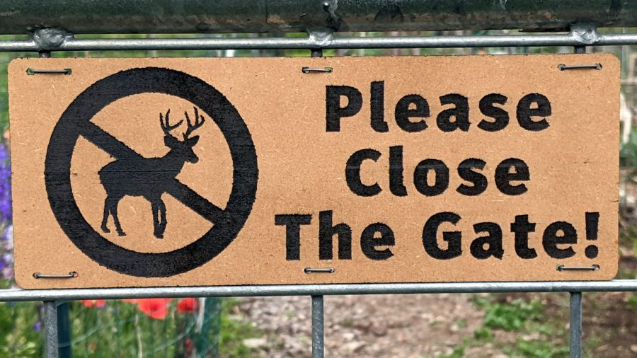
For comparison, they looked nice right after installation:
A warm day let me shoot the engraved signs for the Vassar Community Garden gates with rattlecan black:
Please Close The Gate – masking tape peeled
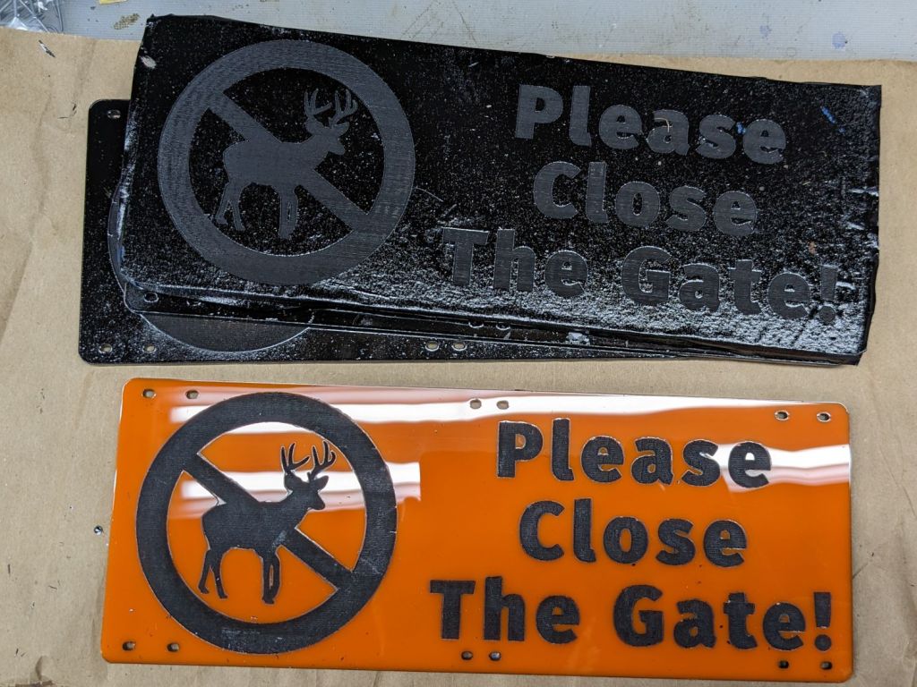
The full sheet of orange acrylic arrived with plastic protective film on both sides, which I planned to use for paint masking. Alas, one side also had a wrinkle running its length that ended up on two signs, so I replaced that film with blue masking tape.
As fate would have it, the first side of the first sign I peeled had masking tape and produced what you see above.
Things went bad in a hurry. The paint had no adhesion whatsoever to the plastic film and fell off in flakes as I peeled the film away:
Please Close The Gate – plastic peeled
I assumed the flakes would just fall off the signs, perhaps with a little persuasion, so I peeled and weeded all the signs before cleaning them up.
Although the paint was fully dry, when the molecularly smooth surface of each paint flake touched the molecularly smooth surface of the newly exposed acrylic, the two instantly and permanently fused together.
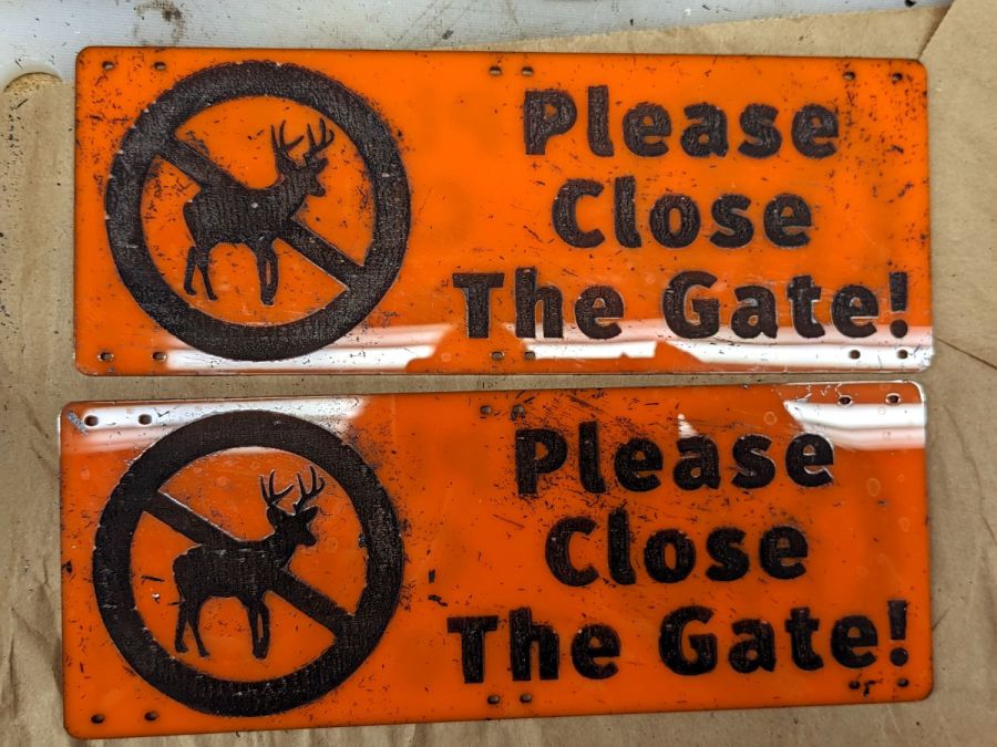
There were a lot of flakes:
Please Close The Gate – plastic peeled – detail
Removal techniques that did not work:
Vacuuming with a brush
Gentle rubbing with a soft cloth
Firm rubbing after spraying with acrylic cleaner
Scraping with a plastic razor blade
So I deployed a P220 grit sanding block and wrecked the glossy surface of both sides of all six signs. I briefly considered trying to recover the finish by sanding them all up through about 2000 grit, then came to my senses: my sanding arm is weak.
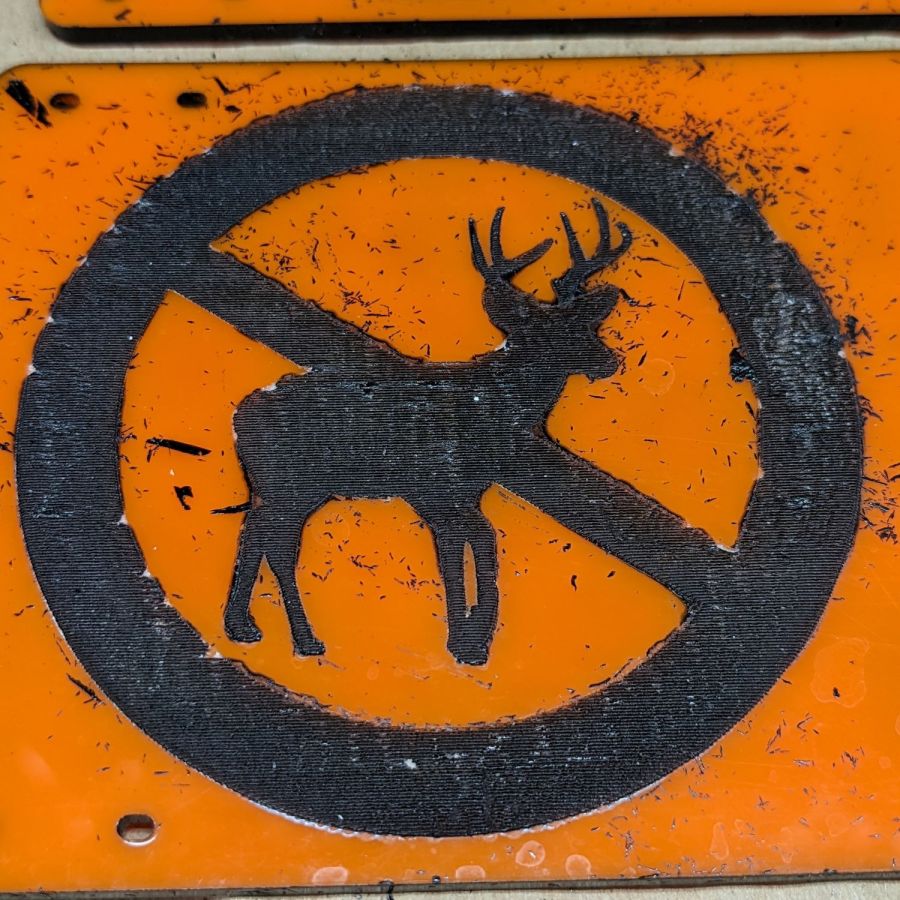
Careful examination of the last picture shows several places around edges of the circle where the plastic film melted into a blob that blocked the paint, rather than vaporizing. I used enough power to engrave only about 0.3 mm deep (because they’re engraved on both sides), but the transition wasn’t fast enough for a clean edge.
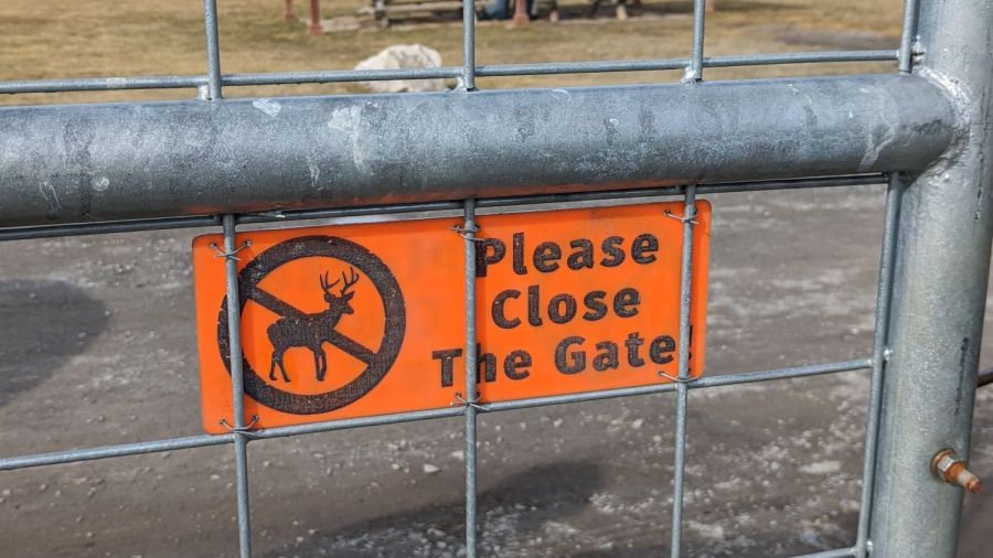
They don’t look as nice as I’d like, but they’re good enough for the purpose:
Please Close The Gate – installed
The acrylic sheet is more see-through than I expected, at least when backlit by bright sunlight.
Please Close The Gate – seethrough
Next: we discover what happens to UV-stabilized orange acrylic and black outdoor paint over the course of a year in garden sunshine.
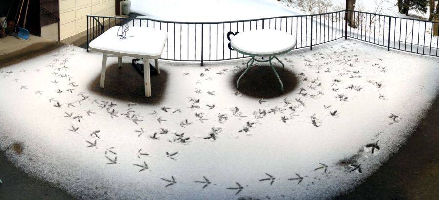
Jake, our affectionate term for whichever turkey is having trouble, eventually walked from right to left closest to the house, down the patio steps, and rejoined the flock. The tip of his “arrow” tracks aims backwards, because all three toes point forward.
It turns out turkeys panic when they’re behind a barrier and see the rest of their flock moving away. A panicked turkey makes a lot of noise while rushing back and forth, the rest of the flock contributes what must be advice, and the resulting tumult suffices to wake the dead.
That would be me, in the bedroom off to the left, but my cold-boot sequence takes long enough that I missed the action.
Some years ago, we discovered how distressed a trapped turkey can get when the flock descended from trees in an adjacent yard, with (a different) Jake landing in the garden, on the other side of the fence from the flock. Over the course of the next several hours, Jake ran back and forth along the fence while the rest of the flock alternated between sympathetic honking and disinterested feeding, until eventually he remembered his wings and managed a short-field takeoff over the fence.


