With the laser cutter set up as before and the scope set up to calculate the time integral of the tube current, this happens:
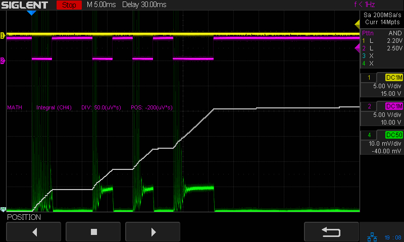
The trigger is the Boolean AND of the top two traces:
- DIR signal = low = left-to-right X axis motion
- L-ON signal = low = laser power supply output enabled
The bottom trace is the laser tube current at 10 mA/div, which is, conveniently, also the scope vertical axis calibration, so you can read “amp” wherever you see “volt”. The four pulses correspond to a single scan line through the usual test pattern:
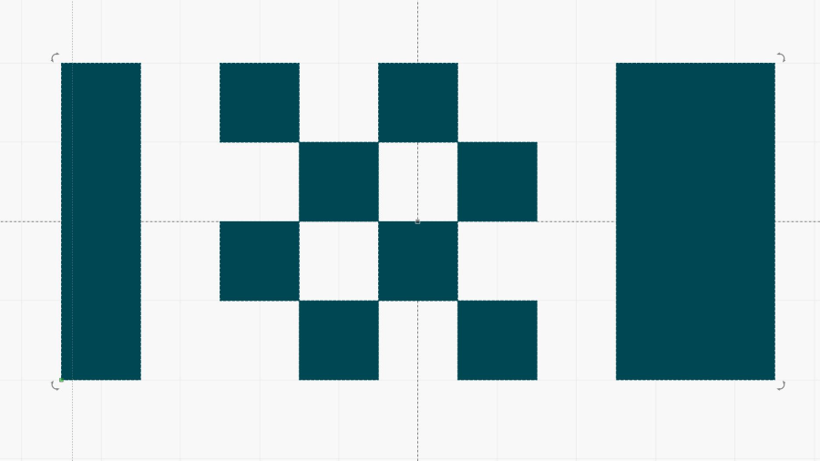
Scanning at 250 mm/s, each 1 mm block occupies 4 ms and the 2 mm block on the right is 8 ms long.
With all that in mind …
The white line in the scope screenshot is the time integral of the current, scaled at 50 µV·s/div and read as 50 µA·s/div due to the 10 mV/div = 10 mA/div equivalence. The integral is pretty much a straight line up and to the right during each pulse, showing that the power supply delivers a nearly constant average current despite the random-looking spikes in the shorter pulses, the oscillations at the start of the longer pulse, and the reasonably flat section after the current settles down.
Say it again: Totally did not expect that.
A closer look at the first pulse of a different line:

Today I Learned: The per-division scale of the white integral line is completely bogus in Zoom mode. Although the display still shows 50 µA·s/div (magenta text obscured near the middle), the integral line rises seven divisions. Some fiddling around showed there is no relation between the calibrations of the normal display and those in Zoom mode.
What is important: seeing the integral as pretty much a straight line with a reasonably constant slope, if you’re willing to ease over the bumps due to the current spikes. The slope of that line (yeah, the derivative of the integral, for a chunky definition of derivative) gives the average tube current.
Referring to the non-Zoomed trace, the integral rises by about 40 µA·s during each 4 ms pulse (and twice that for the 8 ms pulse), for an average current of 40 µA·s / 4 ms = 10 ma. Having previously established 100% PWM corresponds to 24 mA, 40% of 24 mA = 9.6 mA seems about as close as one might expect.
This looks less awful than I expected, fer shure.
More measurements are in order.

Comments
3 responses to “CO₂ Laser Tube Current: Time Integral”
[…] a manual 20 ms pulse at 90% PWM, with the tube current at 20 mA/div. The oscillations at the start of the current pulse seem to excite the tube enough for the light output to stabilize when the real current comes along. […]
[…] as it turns out, engraving lots of small test patterns on scrap acrylic and peering at the results revealed the same […]
[…] worth noting that the tube current has large startup spikes at low power levels in both PWM and analog control, so the spikes are generated internal to the […]