The Bondhus Lifetime Guarantee works, as a replacement wrench just arrived:
A close look at the aligned tips suggests the defective wrench blank was mis-chucked in the machine cutting the ball end:

All’s well that ends well: thank you, Bondhus!
The Smell of Molten Projects in the Morning
Ed Nisley's Blog: Shop notes, electronics, firmware, machinery, 3D printing, laser cuttery, and curiosities. Contents: 100% human thinking, 0% AI slop.

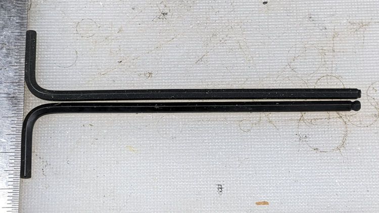
The Bondhus Lifetime Guarantee works, as a replacement wrench just arrived:
A close look at the aligned tips suggests the defective wrench blank was mis-chucked in the machine cutting the ball end:
All’s well that ends well: thank you, Bondhus!
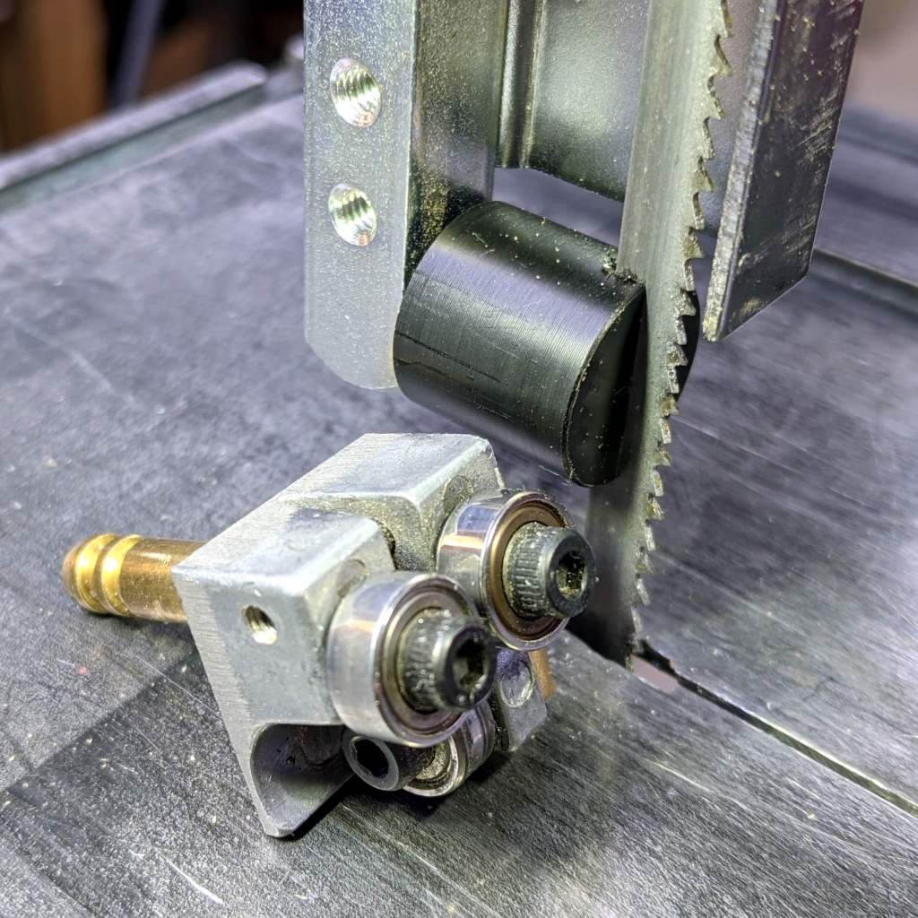
There being nothing like a good new problem to take one’s mind off all one’s old problems:
It’s basically the same as the lower blade guide, except coming from a stick of 5/8 inch acetal. A scant 6 mm stem goes into the vertical square rod, with a flat matching the setscrew coming up from the bottom to hold it in proper alignment.
I came within a heartbeat of cutting the slot parallel to the flat.
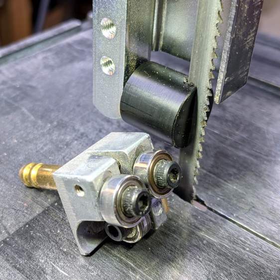
It worked OK while cutting a chunk of stout aluminum tube: so far, so good!
The impressive chunk of hardware is the OEM blade guide, with the brass tube for coolant flow all over the bearings. It’s mostly intended for use with the diamond blade, so I’ll swap it back in when I finally get around to cutting some slate for base plates.

There’s just enough slack in the LED wiring to clip a Tek current probe in there:
Which reveals the LED current waveform:
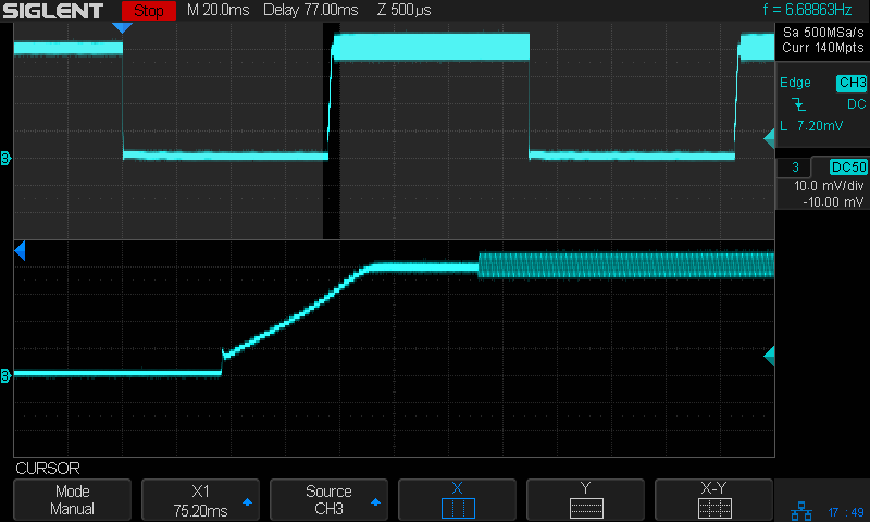
The LED is on continuously, except for the two 75 ms Morse code dits in the upper trace.
The lower trace shows the current ramping up at the end of the first dit, from zero to 400 mA in 1.5 ms.
Clamping the probe around the 6.3 V power supply lead:

The supply current includes maybe 20 mA for the Arduino running the Morse code program and the current ramps up from there to about 250 mA when the LED is on.
The LED drops 2.6 V at 400 mA, so it dissipates a smidge over 1 W. The 2.0 Ω current sense resistor (3.3 Ω in parallel with 5.1 Ω) dissipates 800 mV × 400 mA = 320 mW.
The dissipation from the Bafang headlight output, including the Arduino, is 1.6 W.
The running light ticks along at the hot side of comfortably warm on the Electronics Workbench and runs barely warm in free air out on the bike, so I’ll define it to be Good Enough™.

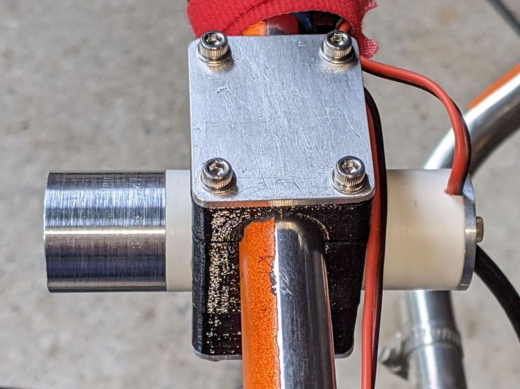
The rear running light definitely has an industrial look:
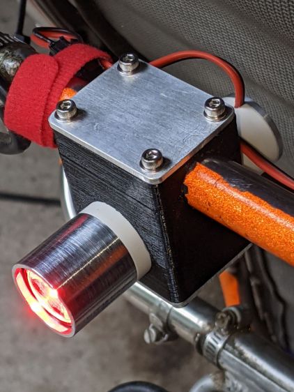
The front of the light has plenty of clearance from the seat mesh:
Out on the road, the 1 W LED appears about as bright as automotive running lights:

The blink pattern makes it perfectly visible in sunlight, although I’d prefer somewhat larger optics:
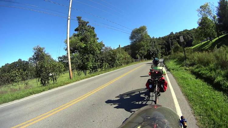
In shaded conditions, it’s downright conspicuous:

At any reasonable distance, the 10° beam covers much of the road behind the bike:
You may not know what the occulting red light represents, but something ahead is worthy of your attention.
The Arduino source code producing the two dits:
// Tour Easy Running Light
// Ed Nisley - KE4ZNU
// September 2021

#include <morse.h>

#define PIN_OUTPUT  13

// second param: true = active low output
LEDMorseSender Morser(PIN_OUTPUT,true,(float)10.0);

void setup()
{
    Morser.setup();

    Morser.setMessage(String("qst de ke4znu "));
    Morser.sendBlocking();

//    Morser.setWPM((float)3.0);
    Morser.setSpeed(75);
    Morser.setMessage(String("i   "));
}

void loop()
{
    if (!Morser.continueSending())
        Morser.startSending();

}
Looks good to me, anyhow.

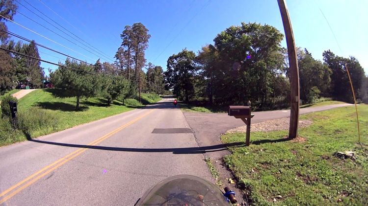
The beaver family living in their pond along the Dutchess Rail Trail near Titusville Rd is doing so well they’ve erected a second lodge:

It’s 500 feet (-ish) upstream from the first lodge and seems somewhat smaller, so perhaps it’s for the kids.

Spotted over a fast food emporium’s parking lot:
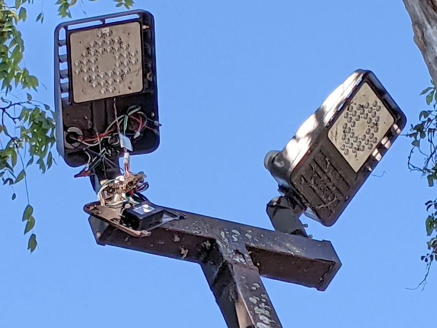
It’s hard to be sure, but I think there’s a paper wasp nest around the bundle of wires just above the transformer / ballast / whatever. Perhaps the repair tech departed with the job unfinished?
As with traffic signals, flashlights, and automotive lighting, the LEDs surely work long after the driver circuitry has given up.

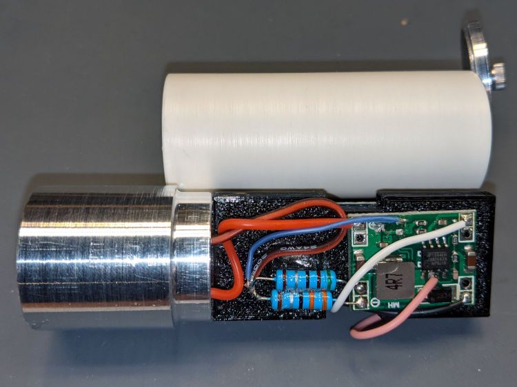
Building the circuit support plate for the amber front running light was entirely too fiddly:
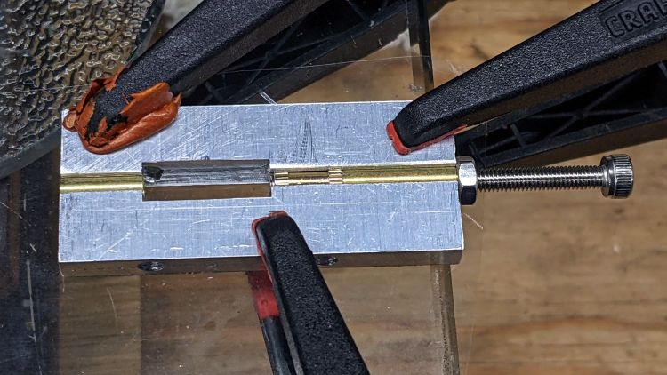
This was definitely easier:
Two pins fit in the small holes to align it with the LED heatsink, with an M3 stud and brass insert holding it in place:
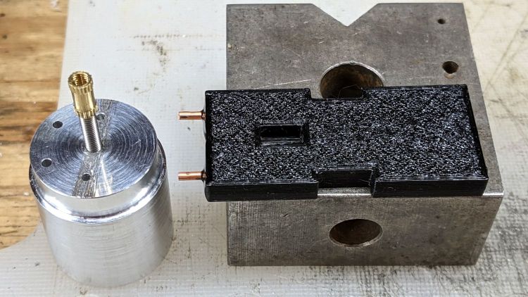
The rectangular hole around the insert let me glop urethane adhesive over it to lock it into the plate, with more goop on the screw and pins to unify heatsink and plate.
The LED wires now emerge from the heatsink on the same side of the plate, simplifying the connections to the MP1584 regulator and current-sense resistor:
The paralleled 5.1 Ω and 3.3 Ω resistors form a 2.0 Ω resistor setting the LED current to 400 mA = 1 W at 2.6 V forward drop. They’re 1 W resistors dissipating a total of 320 mW and get barely warm.
The resistors and wires are stuck in place with clear adhesive, so things shouldn’t rattle around too much.
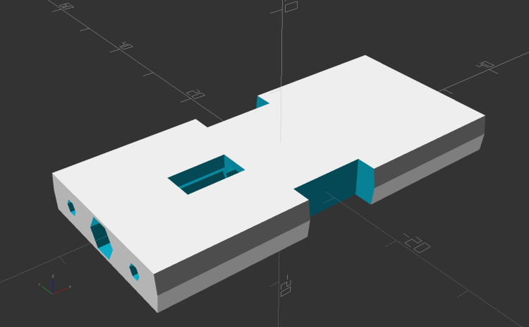
The OpenSCAD source code as a GitHub Gist:
| // Circuit plate for Tour Easy running lights | |
| // Ed Nisley – KE4ZNU – 2021-09 | |
| /* [Hidden] */ | |
| ThreadThick = 0.25; | |
| ThreadWidth = 0.40; | |
| HoleWindage = 0.2; | |
| Protrusion = 0.1; // make holes end cleanly | |
| function IntegerMultiple(Size,Unit) = Unit * ceil(Size / Unit); | |
| ID = 0; | |
| OD = 1; | |
| LENGTH = 2; | |
| inch = 25.4; | |
| //———————- | |
| // Dimensions | |
| // Light case along X axis | |
| LightID = 23.0; | |
| WallThick = 2.0; | |
| Screw = [3.0,6.8,4.0]; // M3 OD=washer, length=nut + washers | |
| Insert = [3.0,4.2,8.0]; // splined brass insert, minus splines | |
| InsertOffset = 10.0; // insert from heatsink end | |
| PinOD = 1.6; // alignment pins | |
| PinOC = 14.0; | |
| PinDepth = 5.0; | |
| Plate = [50.0,LightID,Insert[OD] + 4*ThreadThick]; // overall plate size | |
| WirePort = [10.0,3.0,2*Plate.z]; | |
| NumSides = 2*3*4; | |
| //———————- | |
| // Useful routines | |
| module PolyCyl(Dia,Height,ForceSides=0) { // based on nophead's polyholes | |
| Sides = (ForceSides != 0) ? ForceSides : (ceil(Dia) + 2); | |
| FixDia = Dia / cos(180/Sides); | |
| cylinder(r=(FixDia + HoleWindage)/2, | |
| h=Height, | |
| $fn=Sides); | |
| } | |
| // Circuit plate | |
| module Plate() { | |
| difference() { | |
| intersection() { | |
| cube(Plate,center=true); | |
| rotate([0,90,0]) | |
| cylinder(d=LightID,h=2*Plate.x,$fn=NumSides,center=true); | |
| } | |
| rotate([0,90,0]) rotate(180/6) | |
| translate([0,0,-Plate.x]) | |
| PolyCyl(Screw[ID],2*Plate.x,6); | |
| rotate([0,90,0]) rotate(180/6) | |
| translate([0,0,-Plate.x/2 – Protrusion]) | |
| PolyCyl(Insert[OD],Insert[LENGTH] + InsertOffset + Protrusion,6); | |
| translate([-Plate.x/2 + InsertOffset + Insert[LENGTH]/2,0,Plate.z/2]) | |
| cube([Insert[LENGTH],Insert[OD],Plate.z],center=true); | |
| for (j=[-1,1]) | |
| translate([-Plate.x/2,j*PinOC/2,0]) | |
| rotate([0,90,0]) rotate(180/6) | |
| translate([0,0,-PinDepth]) | |
| PolyCyl(PinOD,2*PinDepth,6); | |
| for (j=[-1,1]) | |
| translate([0,j*(Plate.y/2 – WirePort.y/2),0]) | |
| cube(WirePort,center=true); | |
| } | |
| } | |
| //- Build it | |
| Plate(); | |
