These GRBL configuration constants seem to work well with the DW660 router in the MPCNC gantry:
| $$ | |
| $0=10 | |
| $1=255 | |
| $2=0 | |
| $3=2 | |
| $4=0 | |
| $5=0 | |
| $6=0 | |
| $10=1 | |
| $11=0.010 | |
| $12=0.002 | |
| $13=0 | |
| $20=1 | |
| $21=1 | |
| $22=1 | |
| $23=0 | |
| $24=500.000 | |
| $25=2500.000 | |
| $26=250 | |
| $27=3.000 | |
| $30=30000 | |
| $31=0 | |
| $32=0 | |
| $100=100.000 | |
| $101=100.000 | |
| $102=400.000 | |
| $110=8000.000 | |
| $111=8000.000 | |
| $112=3000.000 | |
| $120=2000.000 | |
| $121=2000.000 | |
| $122=2000.000 | |
| $130=635.000 | |
| $131=465.000 | |
| $132=103.000 | |
| —– | |
| $n | |
| $N0=F150 | |
| $N1=G10L2P1X-633Y-463Z-3 | |
| —– | |
| $# | |
| [G54:-633.000,-463.000,-3.000] | |
| [G55:0.000,0.000,0.000] | |
| [G56:0.000,0.000,0.000] | |
| [G57:0.000,0.000,0.000] | |
| [G58:0.000,0.000,0.000] | |
| [G59:0.000,0.000,0.000] | |
| [G28:-418.670,-282.016,-3.000] | |
| [G30:-628.000,-3.000,-3.000] | |
| [G92:0.000,0.000,0.000] | |
| [TLO:0.000] | |
| [PRB:0.000,0.000,0.000:0] |
The overall XY travel is slightly smaller than the initial configuration, because the router sticks out further than the penholder I’d been using. Increasing the $27 Homing Pulloff distance to 3 mm leaves a comfortable space beyond the limit switches after homing to the positive end:
Adjusting the $13[01] XY travel distances and switch positions on the other end of the rail leaves a similar comfort zone at the negative end:

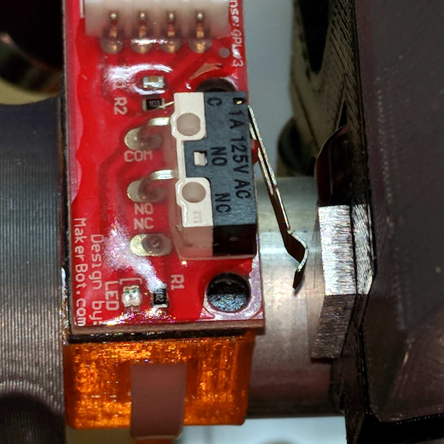
Both switches now live on the rear X-axis rail and appear as seen from behind the bench; they just look backwards. The Y-axis switches are on the left rail and look exactly the same.
The XY travel works out to 630 × 460 mm = 24.8 × 18.1 inch, which is Good Enough.
Some fiddling with the Z axis limit switch tape mask produces a nice round 100 mm = 3.9 inch vertical travel. The Z-axis rails just barely clear the table at the lower limit and just barely stay in the bottom bearings at the upper limit, so it’s a near thing. In practical terms, the rails or the tool will smash into the workpiece sitting atop the table before the limit switch trips.
Setting both $20=1 Soft Limits and $21=1 Hard Limits may be excessive, but I vastly prefer having the firmware detect out-of-range moves and the hardware forcibly shut down if the firmware loses track of its position, rather than letting it grind away until I can slap the BRS. The steppers aren’t powerful enough to damage anything, of course, so it’s a matter of principle.
The $N0=F150 sets the initial speed, as the default F0 seems to (sometimes) confuse bCNC’s auto-level grid probing.
The $N1=G10L2P1X-633Y-463Z-3 sets the default G54 coordinate origin to the front-left corner, with Z=0 at the home position up top, so as to prevent surprises. I expect to use G55 for most work holder touchoffs, although we’ll see how that plays out.
The G28 and G30 settings depend on the tool change location and the Z-axis probe location, so they’re still not cast in concrete.
