The Smell of Molten Projects in the Morning

Ed Nisley's Blog: Shop notes, electronics, firmware, machinery, 3D printing, laser cuttery, and curiosities. Contents: 100% human thinking, 0% AI slop.

Month: May 2017

  • Arduino Joystick

    A bag of sub-one-dollar resistive joysticks arrived from halfway around the planet:

    Arduino UNO - resistive joystick
    Arduino UNO – resistive joystick

    A quick-and-dirty test routine showed the sticks start out close to VCC/2:

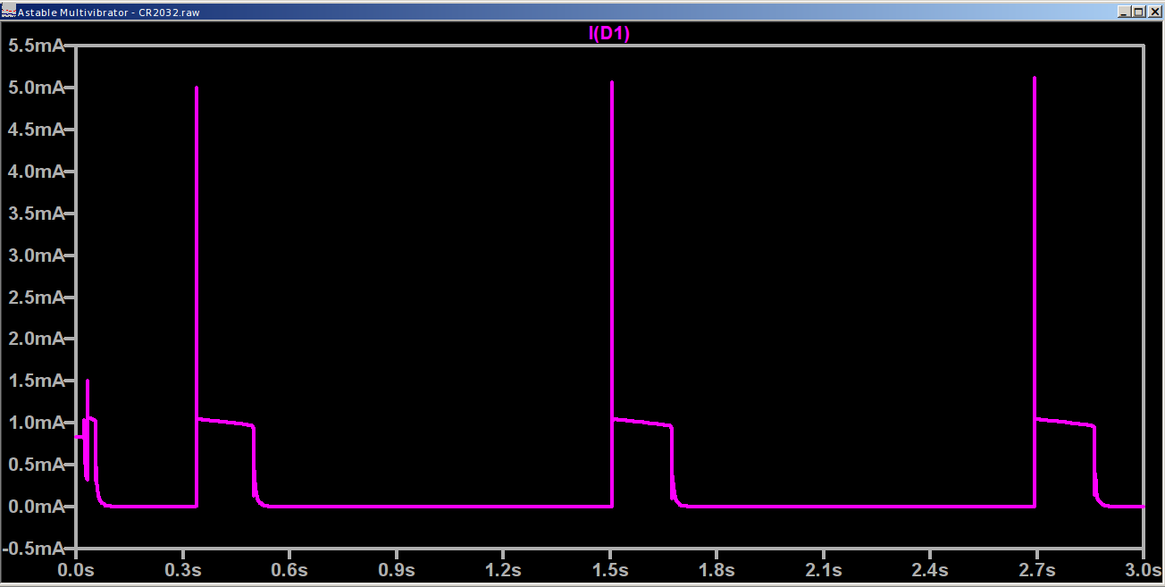
    Welcome to minicom 2.7
    
    OPTIONS: I18n
    Compiled on Feb  7 2016, 13:37:27.
    Port /dev/ttyACM0, 10:23:45
    
    Press CTRL-A Z for help on special keys
    
    Joystick exercise
    Ed Nisley - KE4ZNU - May 2017
    00524 - 00513 - 1
    

    That’s from minicom on the serial port, as the Arduino IDE’s built-in serial monitor ignores bare Carriage Return characters.

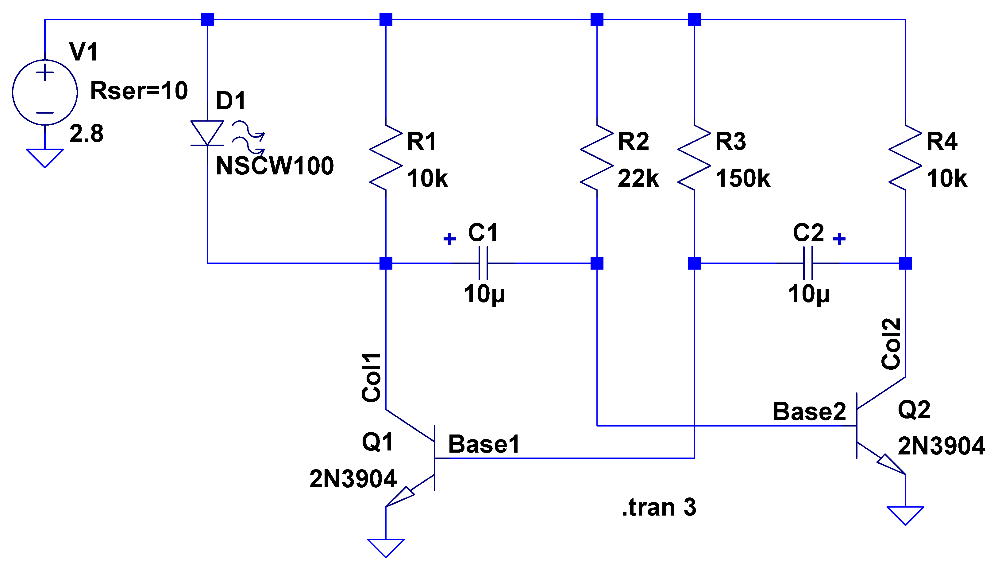
    The joystick hat tilts ±25° from its spring-loaded center position, but the active region seems to cover only 15° of that arc, with a 5° dead zone around the center and 5° of overtravel at the limits. This is not a high-resolution instrument intended for fine motor control operations.

    The analog input values range from 0x000 to 0x3FF across the active region. Aim the connector at your tummy to make the axes work the way you’d expect: left / down = minimum, right / up = maximum.

    The delay(100) statements may or may not be needed for good analog input values, depending on some imponderables that seem not to apply for this lashup, but they pace the loop() to a reasonable update rate.

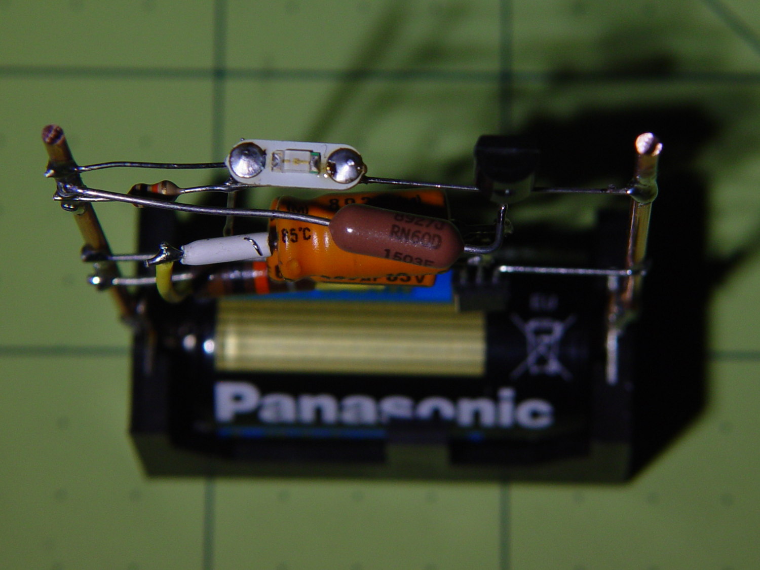
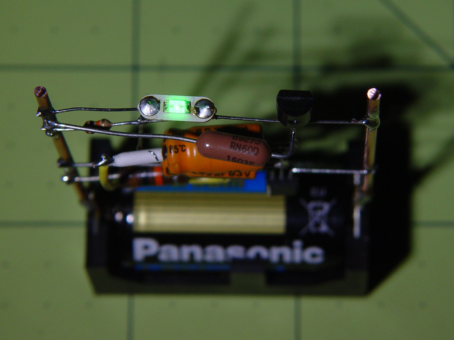
    Pushing the hat toward the PCB activates the simple switch you can see in the picture. It requires an external pullup resistor (hence the INPUT_PULLUP configuration) and reports low = 0 when pressed.

    Those are 0.125 inch (exactly!) holes on a 19.5×26.25 mm grid in a 26.5×34.25 mm PCB. Makes no sense to me, either.

    The trivial Arduino source code as a GitHub Gist:

    // Joystick exercise
    #define JOYX A0
    #define JOYY A1
    #define BUTTON 7
    int JoyX,JoyY;
    boolean Button;
    //– Helper routine for printf()
    int s_putc(char c, FILE *t) {
    Serial.write(c);
    }
    void setup() {
    Serial.begin (9600);
    fdevopen(&s_putc,0); // set up serial output for printf()
    Serial.println ("Joystick exercise");
    Serial.println ("Ed Nisley – KE4ZNU – May 2017");
    pinMode(BUTTON,INPUT_PULLUP);
    }
    void loop() {
    JoyX = analogRead(JOYX);
    delay(100);
    JoyY = analogRead(JOYY);
    delay(100);
    Button = digitalRead(BUTTON);
    printf("%05d – %05d – %1d\r",JoyX,JoyY,Button);
    }
  • XTC-3D Epoxy Coating: Results

    Having figured the mixing ratios, found the mixing trays, and donned my shop apron, I buttered up several iterations of the badge reel case to see how XTC-3D epoxy works on the little things around here.

    In all cases, I haven’t done any sanding, buffing, or primping, mostly because I’m not that interested in the final surface finish.

    A single coat produces a glossy finish with ripples from the printed threads:

    XTC-3D - Hilbert - reflective
    XTC-3D – Hilbert – reflective

    Seen straight on, without the glare, a little speck toward the lower right corner shows that cleanliness is next to impossible around here:

    XTC-3D - lines - direct
    XTC-3D – lines – direct

    An additional coat atop a Hilbert-curve upper surface comes out somewhat smoother:

    XTC-3D - Hilbert - reflective 2
    XTC-3D – Hilbert – reflective 2

    Another view, with less glare, shows the pattern a bit better:

    XTC-3D - Hilbert - reflective 1
    XTC-3D – Hilbert – reflective 1

    With no glare, the 3D Honeycomb infill shows through the surface:

    XTC-3D - Hilbert - direct
    XTC-3D – Hilbert – direct

    Coating the surface with epoxy definitely makes it more transparent / less translucent by filling in the air gaps.

    The sides of that part have only one coat and still show typical 3D printed striations.

    Three coats wipe out the striations, along with all other surface detail:

    XTC-3D - Bezel - front oblique
    XTC-3D – Bezel – front oblique

    The bolt head recesses collected enough epoxy to require reaming / milling, which certainly isn’t what you want in that situation. The bolt holes also shrank, although my usual hand-twisted drill would probably suffice to clear the epoxy.

    Another view shows a glint from the smooth surface filling the upper-right recess:

    XTC-3D - Bezel - front
    XTC-3D – Bezel – front

    Three coats definitely hides the 3D printed threads, although you can see some ridges and edges:

    XTC-3D - heavy - oblique
    XTC-3D – heavy – oblique

    The epoxy isn’t perfectly self-leveling, probably due to my (lack of) technique:

    XTC-3D - heavy - reflection
    XTC-3D – heavy – reflection

    Blowing out the contrast shows the surface finish:

    XTC-3D - heavy - direct - boost
    XTC-3D – heavy – direct – boost

    Those scratches come from fingernails, after the overnight curing time. The surface is hard, but not impervious to scratching, which is about what you’d expect for a clear epoxy.

    Slightly over-thinning the XTC-3D with denatured alcohol in a 0.7 : 0.3 : 0.3 by weight ratio produced a watery liquid that penetrated directly into the surface:

    XTC-3D - thinned - oblique
    XTC-3D – thinned – oblique

    The finish depends critically on what’s below the surface and how much epoxy you apply. I tried to spread it uniformly with a foam brush, but the center came out somewhat rougher than the outer edge:

    XTC-3D - thinned - oblique
    XTC-3D – thinned – oblique

    The striations along the sides filled in a bit, but surely not enough to satisfy anybody who worries about such things.

    A specular reflection shows the changing surface smoothness:

    XTC-3D - thinned - oblique reflective
    XTC-3D – thinned – oblique reflective

    Perhaps two coats of thinned epoxy would produce a watertight / airtight part, without changing the overall dimensions by very much. The mechanical properties depend almost entirely on the plastic-to-plastic bond, so I doubt a thin epoxy layer would improve its pressure-handling capabilities.

    Few of the parts I make will benefit from an epoxy coating and I definitely don’t want to get into post-processing the parts just to improve their looks!

  • Wearable LED vs. Astable Multivibrator vs. Dead Lithium Cells

    Mashing the wearable LED from the completely dead CR2032 cell with a classic astable multivibrator circuit and a not-dead-yet CR123 cell produced a pure-analog desktop blinky:

    CR123A Astable - front
    CR123A Astable – front

    Of course, I managed to swap the base resistors, which meant the LED stayed on most of the time, which accounts for the slightly off-kilter brown resistor just under the LED.

    It doesn’t look like much with the LED off:

    CR123A Astable - top - off
    CR123A Astable – top – off

    Running from a 2.8 V (= dead) lithium cell, the LED lights a dark room at 3 mA:

    CR123A Astable - top - on
    CR123A Astable – top – on

    The LTSpice schematic gives the details:

    Astable Multivibrator - CR2032 - schematic
    Astable Multivibrator – CR2032 – schematic

    The LED definitely didn’t come from Nichia and the 2N3704 transistors aren’t the 2N3904s found in the LTSpice library, but, by and large, this is the kind of circuit where nearly anything will work.

    The actual LED current obviously depends critically on the particular LED and the cell voltage, so this represents more of a serving suggestion than an actual prediction:

    Astable Multivibrator - CR2032 - waveform
    Astable Multivibrator – CR2032 – waveform

    Indeed, a Tek current probe clamped around one of those 10 AWG copper wires shows a much more enthusiastic LED current (1 mA/div):

    Astable - CR123A 2.8 V - 1 mA -green
    Astable – CR123A 2.8 V – 1 mA -green

    I don’t trust the baseline very much. The simulation & back of the envelope agree: the LED-off current should be around 400 µA (which doesn’t depend on the LED at all), so it’s in the right ballpark.

    Your mileage will definitely differ.

    It runs without a trace of software, which everybody at Squidwrench thought was wonderful …

  • Relics of the Empire: Bearing Samples

    Schatz Manufacturing, a major bearing producer in Poughkeepsie, made a sample case to show off their wares:

    Schatz Ball Bearings
    Schatz Ball Bearings

    You can tell by the yellowed backing paper that these have been around for a looong time.

    It turns out that Poughkeepsie had two bearing manufacturers. Federal Bearings went into the products of other locally important industries:

    Federal Bearings
    Federal Bearings

    A detailed look shows what was important, back in the day:

    Federal Bearings - Detail - IBM Card Sorter
    Federal Bearings – Detail – IBM Card Sorter

    Schatz and Federal later merged into Shatz Federal Bearings, eventually become Shatz Bearings, and still operate in Poughkeepsie. Some of their industrial waste remains here, too.

    Out in the garage I still have a few grease pilots (*) from the final Schatz Federal downsizing / going-out-of-business / moving / whatever sale. A friend bought several sets of heavy-duty steel chests-of-drawers which contained, very much to his surprise, a huge assortment of grease pilots, ranging in size from fit-on-your-thumb to cover-a-dinner-plate, which he obviously had no use for. He unloaded them on me with a phrase that has lived on forevermore:

    They’re a buck apiece, unless you take all of them, in which case they’re free.

    You’ll find the sample cases on the top floor of Adriance Library, should you ever be in town.

    Taken handheld in ambient light to avoid harsh flash shadows, then perspective-distorted to make them look like I was standing directly in front of the reflective plastic covers.

    (*) Different from a “pilot bearing”. A “grease pilot” is a two-part circular steel assembly used to inject grease into the bearing races before snapping the shields in place. They’re painstakingly machined to cup the balls and fill the gaps, with a pipe fitting on the back surface for the grease pump.

  • Dropbox Tour: To Keep Learning, Click Cancel

    After copying a Digital Machinist column to my Dropbox folder, I went to the site to get the link, discovered they improved the UI, declined a Flash-based tour of the new features, and got this baffling confirmation dialog:

    Dropbox - tour exit dialog
    Dropbox – tour exit dialog

    So. Many. Wrongs.

  • Arduino vs. Significant Figures: BigNumber Library

    The BigNumber library wraps the bc arbitrary precision calculator into a set of Arduino routines that seem like a reasonable basis for DDS calculations requiring more than the half-dozen digits of a floating point number or the limited range of scaled fixed point numbers tucked into an long int.

    Treating programming as an experimental science produces some Arduino source code and its output as a GitHub Gist:

    // BigNumber exercise
    #include "BigNumber.h"
    //– Helper routine for printf()
    int s_putc(char c, FILE *t) {
    Serial.write(c);
    }
    void setup ()
    {
    Serial.begin (115200);
    fdevopen(&s_putc,0); // set up serial output for printf()
    Serial.println ("BigNumber exercise");
    Serial.println ("Ed Nisley – KE4ZNU – April 2017");
    #define WHOLES 10
    #define FRACTS 10
    printf("Fraction digits: %d\n",FRACTS);
    BigNumber::begin (FRACTS);
    char *pBigNumber;
    #define BUFFLEN (WHOLES + FRACTS)
    char NumString[BUFFLEN];
    BigNumber Tenth = "0.1"; // useful constants
    BigNumber Half = "0.5";
    BigNumber One = 1;
    BigNumber Two = 2;
    BigNumber ThirtyTwoBits = Two.pow(32);
    Serial.println(ThirtyTwoBits);
    BigNumber Oscillator = "125000000";
    Serial.println(Oscillator);
    BigNumber HertzPerCount;
    HertzPerCount = Oscillator / ThirtyTwoBits;
    Serial.println(HertzPerCount);
    BigNumber CountPerHertz;
    CountPerHertz = ThirtyTwoBits / Oscillator;
    Serial.println(CountPerHertz);
    BigNumber TestFreq = "60000";
    Serial.println(TestFreq);
    BigNumber DeltaPhi;
    DeltaPhi = TestFreq * CountPerHertz;
    Serial.println(DeltaPhi);
    long DeltaPhiL;
    DeltaPhiL = DeltaPhi;
    printf("Long: %ld\n",DeltaPhiL);
    Serial.println("0.1 Hz increment …");
    Serial.println(TestFreq + Tenth);
    DeltaPhi = (TestFreq + Tenth) * CountPerHertz;
    Serial.println(DeltaPhi);
    TestFreq = DeltaPhi * HertzPerCount;
    Serial.println(TestFreq);
    Serial.println("Rounding DeltaPhi up …");
    DeltaPhi += Half;
    Serial.println(DeltaPhi);
    TestFreq = DeltaPhi * HertzPerCount;
    Serial.println(TestFreq);
    pBigNumber = DeltaPhi.toString();
    printf("String: %04x → %s\n",pBigNumber,pBigNumber);
    free(pBigNumber);
    DeltaPhiL = DeltaPhi;
    printf("Unsigned: %ld\n",DeltaPhiL);
    pBigNumber = "59999.9";
    TestFreq = pBigNumber;
    Serial.println(TestFreq);
    DeltaPhi = TestFreq * CountPerHertz;
    Serial.println(DeltaPhi);
    Serial.println("Rounding DeltaPhi up …");
    DeltaPhi = TestFreq * CountPerHertz + Half;
    Serial.println(DeltaPhi);
    DeltaPhiL = DeltaPhi;
    int rc = snprintf(NumString,BUFFLEN,"%ld",DeltaPhiL);
    if (rc > 0 && rc < BUFFLEN) {
    printf("String length: %d\n",rc);
    }
    else {
    printf("Whoops: %d for %ld\n",rc,DeltaPhiL);
    strncpy(NumString,"123456789",sizeof(NumString));
    NumString[BUFFLEN-1] = 0;
    printf(" forced: %s\n",NumString);
    }
    printf("Back from string [%s]\n",NumString);
    DeltaPhi = NumString;
    Serial.println(DeltaPhi);
    TestFreq = DeltaPhi * HertzPerCount;
    Serial.println(TestFreq);
    }
    void loop () {
    }
    view raw BigNumTest.ino hosted with ❤ by GitHub
    BigNumber exercise
    Ed Nisley – KE4ZNU – April 2017
    Fraction digits: 10
    4294967296
    125000000
    0.0291038304
    34.3597383680
    60000
    2061584.3020800000
    Long: 2061584
    0.1 Hz increment …
    60000.1000000000
    2061587.7380538368
    60000.0998830384
    Rounding DeltaPhi up …
    2061588.2380538368
    60000.1144349536
    String: 045e → 2061588.2380538368
    Unsigned: 2061588
    59999.9
    2061580.8661061632
    Rounding DeltaPhi up …
    2061581.3661061632
    String length: 7
    Back from string [2061581]
    2061581
    59999.9037798624
    view raw BigNumTest.txt hosted with ❤ by GitHub

    All that happened incrementally, as you might expect, with the intent of seeing how it works, rather than actually doing anything.

    Some musings, in no particular order:

    The library soaks up quite a hunk of program space:

    Sketch uses 13304 bytes (43%) of program storage space. Maximum is 30720 bytes.
    

    I think you could cut that back a little by eliminating unused bc routines, like square root / exponential / modulus.

    That test code also blots up quite a bit of RAM:

    Global variables use 508 bytes (24%) of dynamic memory, leaving 1540 bytes for local variables. Maximum is 2048 bytes.
    

    All the BigNumber variables live inside the setup() function (or whatever it’s called in Arduino-speak), so they count as local variables. They’re four bytes each, excluding the dynamically allocated storage for the actual numbers at roughly a byte per digit. With 10 decimal places for all numbers, plus (maybe) an average of half a dozen integer digits, those ten BigNumbers soak up 200 = 10 × (4 + 16) bytes of precious RAM.

    You can load a BigNumber from an int (not a long) or a string, then export the results to a long or a string. Given that controlling a DDS frequency with a knob involves mostly adding and subtracting a specific step size, strings would probably work fine, using snprintf() to jam the string equivalent of a long into a BigNumber as needed.

    You must have about ten decimal places to hold enough significant figures in the HertzPerCount and CountPerHertz values. The library scale factor evidently forces all the numbers to have at least that many digits, with the decimal point stuck in front of them during string output conversions.

    The biggest integers happen in the Oscillator and ThirtyTwoBits values, with 9 and 10 digits, respectively.

    It looks useful, although I’m uncomfortable with the program space required. I have no way to estimate the program space for a simpleminded DDS controller, other than knowing it’ll be more than I estimate.

    While poking around, however, I discovered the Arduino compiler does provide (limited) support for long long int variables. Given a 64 bit unit for simple arithmetic operations, a simpler implementation of fixed point numbers may be do-able: 32 bits for the integer and fraction should suffice! More on that shortly.

  • XTC-3D Epoxy Coating

    The striations inherent in the DIY-grade 3D printing process don’t bother me all that much, but I got some XTC-3D epoxy to see what I’ve been missing. The impressive scrap pile from the badge reel holder provided test pieces:

    XTC-3D Epoxy - test pieces - holders
    XTC-3D Epoxy – test pieces – holders

    If I were serious, I’d figure out a better way to hold the parts. For now, I jammed a watch crab into the back and trapped the bezel on a watch holder, but … ick.

    Weighing the components seems the least-awful way to get the small quantities I need. The instructions recommend 100:43 by weight of resin (A) : hardener (B):

    XTC-3D Epoxy - weighing pan
    XTC-3D Epoxy – weighing pan

    For these tiny parts, 2 g + 0.9 g was way too much and 1 g + 0.4 g seemed entirely adequate. If you slowly drool resin into the pan, drool slightly less than half that much hardener, and it’ll be about as close as you can get. The hardener is much less viscous than the resin: drool carefully.

    The stuff might be self-leveling on larger parts, but on these small surfaces it’s better (IMO) to dry-brush multiple layers: you can see thicker and thinner sections in the first picture. The recoat time runs about 1-½ h.

    The instructions recommend acetone or denatured alcohol as a thinning agent, at 10 to 25% of the resin volume, with curing times up to 24 h. Alcohol seems less likely to produce Bad Results, because it won’t evaporate instantly. Neither will affect PETG, but if you’re using another plastic, keep its solvent list in mind.

    I tried alcohol with a by-weight amounts around 0.7 : 0.3 : 0.3 g, obviously overshooting both the hardener and the alcohol by a few drops. The end result resembled thick water, brushed on easily, and penetrated the surface easily.

    A first coat of thinned epoxy should fill voids and unify the surface without changing the dimensions very much, with subsequent coats leveling the striations.

    More pix after more layers and more curing …