A recent QEX article (Jan/Feb 2017 2016; sorry ’bout that), Crystal Measurement Parameters Simplified, Chuck Adams K7QO) suggested a simplified version of the K8IQY crystal parameter test fixture would work just as well for low-frequency quartz resonators:
The resistive pads eliminate the fussy toroids and their frequency dependence.
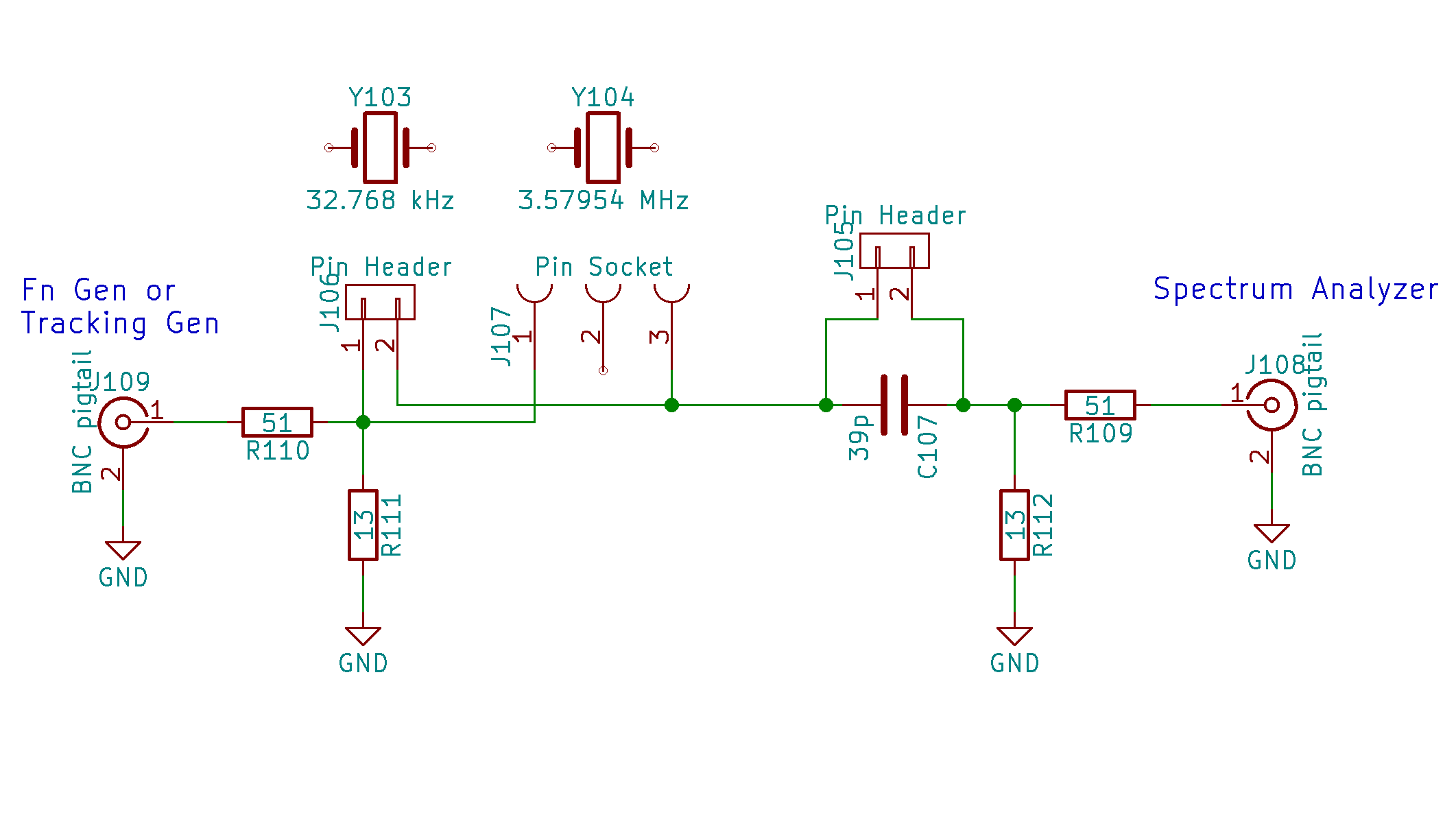
Tossing a handful of parts on a small proto board:

I found two absurdly long hunks of RG-174 coax with BNC connectors, so that’s how it connects to the outside world; sacrificing a short SMA jumper would reduce the clutter, but that’s in the nature of fine tuning. At the frequencies this fixture will see, coax properties don’t matter.
I can’t think of a better way to mount those AT26 cans than by soldering the wire leads directly to a pin header; pushing them under spring clips seems fraught with peril, not to mention excessive stray capacitance.
Measure the actual in-circuit capacitance for the 33 pF cap (shown as 39 pF in the schematic, it’s not critical), which worked out to 34.6 pF. That’s the external series capacitance Cx.
The overall procedure, slightly modified from the original:
- Measure C0 with resonator in capacitance fixture
- Solder resonator to pins
- Remove jumper to put capacitor Cx in series
- Find series-resonant peak = Fc
- Install jumper to short Cx
- Find series-resonant peak = Fs < Fc
- Remember the peak amplitude
- Unsolder crystal
- Install suitable trimpot = Rm in socket
- Adjust trimpot to produce same output amplitude
Crunch the numbers to get the crystal’s motional parameters:
Rm = trimpot resistance
Lm = 1 / [4 π2 (Fs + Fc) (Fs - Fc) (C0 + Cx)]
Cm = 1 / [(2 π Fs)2 Lm]
Q = [2 π Fs Lm] / Rm
Then you’re done!

Comments
5 responses to “Quartz Resonator Test Fixture”
For an AT26 socket, I’d probably use FCI “Minisert” contacts. Tektronix used to use these as IC and transistor sockets in high frequency circuitry, they’re quite small. I’d use ’em because I have them on hand, they stopped making them in 2010.
[…] to see if the resonator test fixture produced meaningful results, I plugged a 3.57954 MHz color burst crystal into the […]
[…] Soldering a 32.768 kHz quartz tuning fork resonator into the test fixture: […]
[…] first pass at the crystal tester used a manual jumper to switch the 33 pF series capacitor in / out of the […]
[…] make it worse, I also botched the QEX reference, which should be Jan/Feb 2016, not 2017. Verily, having a column go read-only makes the errors jump […]