The Smell of Molten Projects in the Morning

Ed Nisley's Blog: Shop notes, electronics, firmware, machinery, 3D printing, laser cuttery, and curiosities. Contents: 100% human thinking, 0% AI slop.

Month: April 2016

  • It’s Right on Red After Stopping

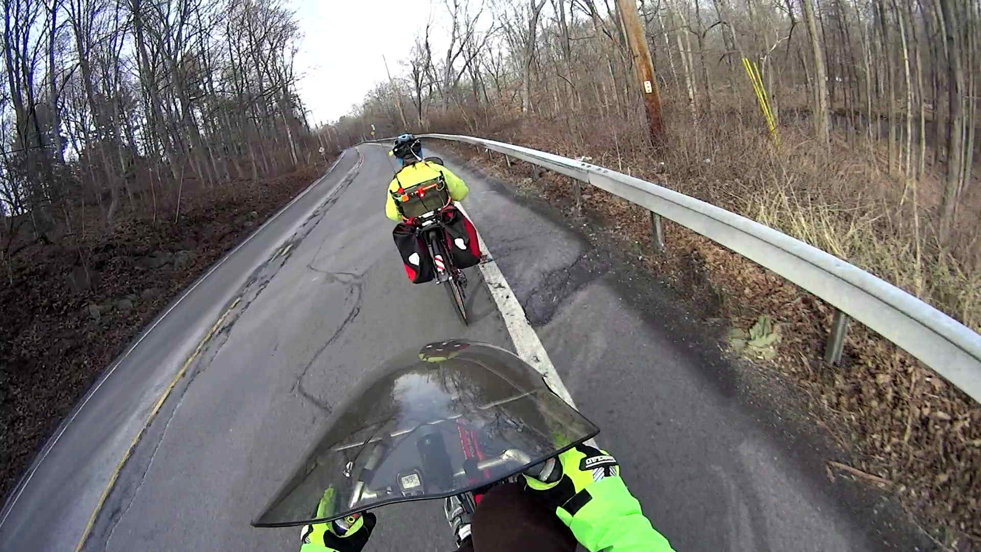
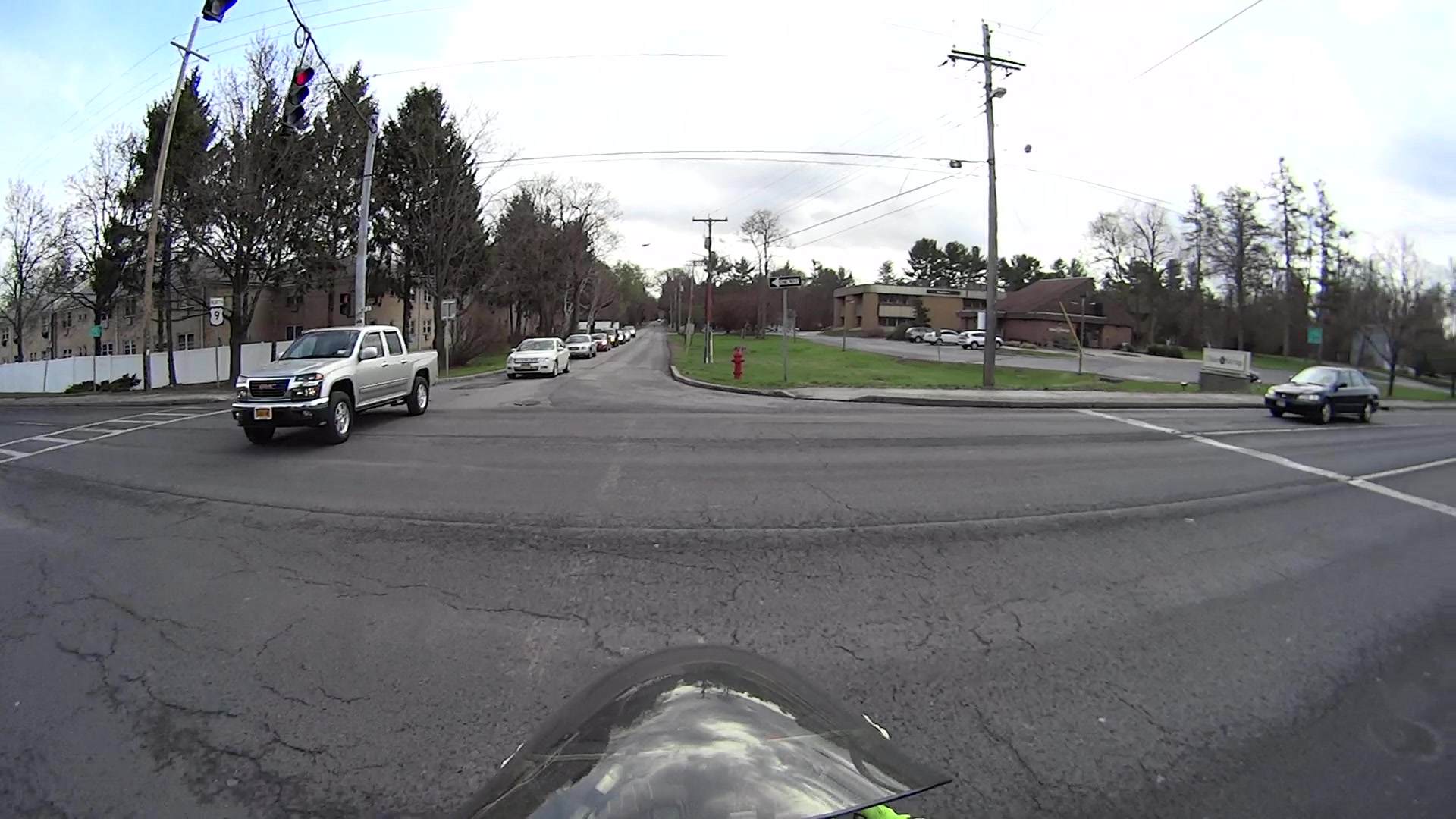
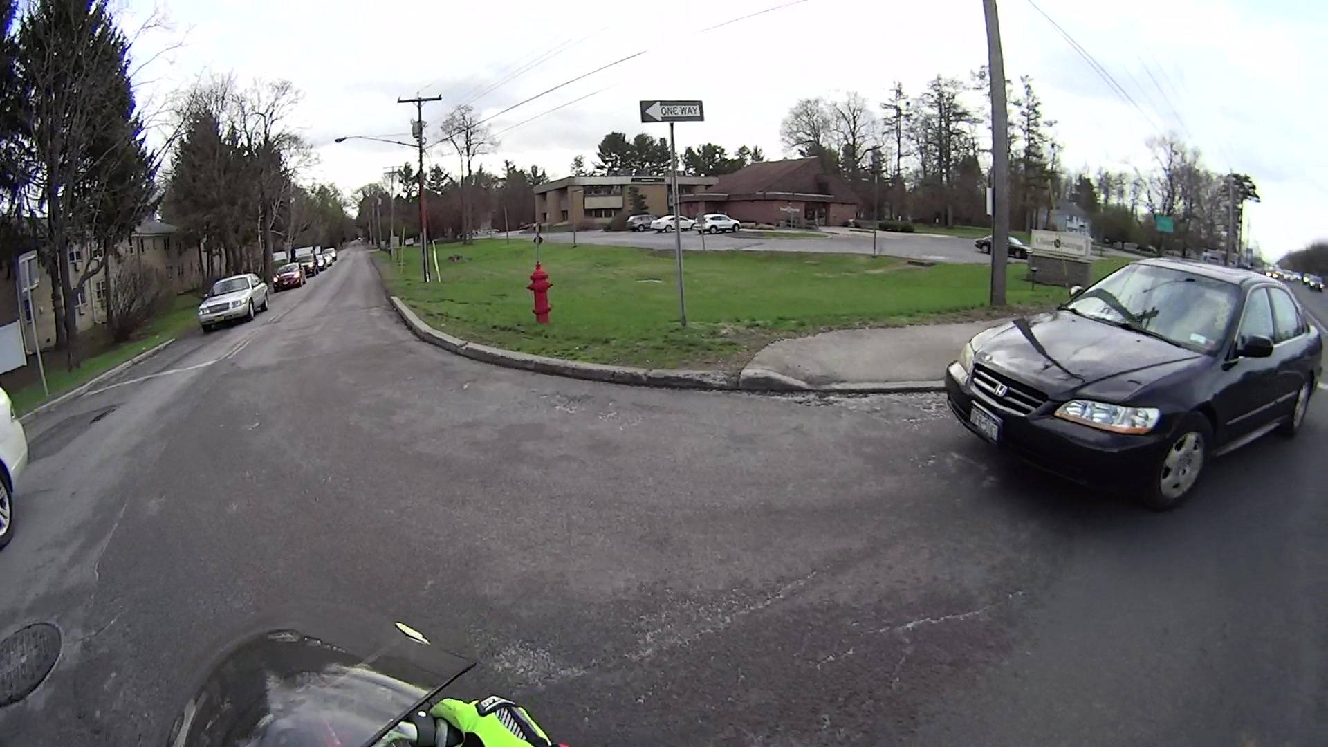
    I’m returning home after accompanying Mary to her morning of volunteering in the Locust Grove veggie gardens. The Locust Grove gate faces predominantly left-turning traffic from Beechwood Avenue, so I’ll be watching the vehicles approaching head-on.

    T = 0.000 – Signal turns green:

    Rt 9 Locust Grove - Right on Red - front camera - 0135
    Rt 9 Locust Grove – Right on Red – front camera – 0135

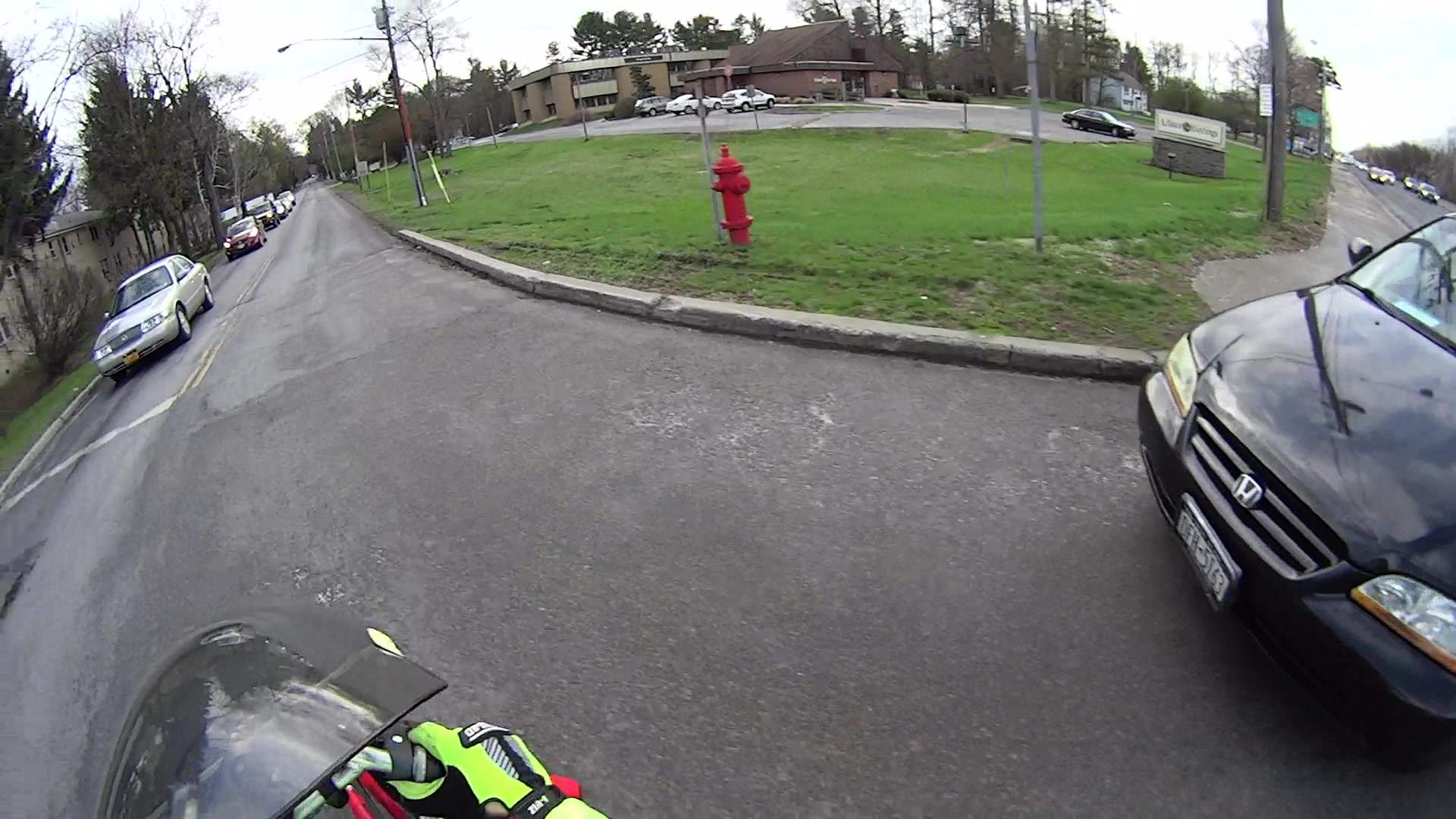
    T = 2.500 – Entering the intersection:

    Rt 9 Locust Grove - Right on Red - front camera - 0270
    Rt 9 Locust Grove – Right on Red – front camera – 0270

    I don’t start pedaling until the signal in my direction actually turns green, because drivers have been known to blow through intersections with a fresh red signal. Two seconds seems like a reasonable delay.

    T = 5.500 – Three lanes later, nearing the midline of Rt 9 and still accelerating:

    Rt 9 Locust Grove - Right on Red - front camera - 0465
    Rt 9 Locust Grove – Right on Red – front camera – 0465

    T = 5.917 – The black car in the right lane is moving and I begin to look that way:

    Rt 9 Locust Grove - Right on Red - front camera - 0490
    Rt 9 Locust Grove – Right on Red – front camera – 0490

    I cannot tell from the video whether the driver actually stopped (as you’re required to do for “right on red after stop“, but nobody actually does) or just slowed into a rolling stop for the turn.

    Why not slam to a stop in the middle of Rt 9 in front of the left-turning traffic? Come for a ride with me and we’ll try that out. I’ll shout “LOOK OUT!” at some inopportune time when you’re in the middle of traffic and not expecting it, whereupon you must hit the brakes and deal with the consequences.

    T = 7.117 – One second later, I’m beginning to veer left, directly toward the stream of oncoming traffic turning toward me:

    Rt 9 Locust Grove - Right on Red - front camera - 0562
    Rt 9 Locust Grove – Right on Red – front camera – 0562

    In round numbers, the black car moved 35 feet in 1.2 s between those frames: 30 feet/s = 20 mph.

    T = 7.750 – The white car on my right continues turning and I’ll definitely clear its rear:

    Rt 9 Locust Grove - Right on Red - front camera - 0600
    Rt 9 Locust Grove – Right on Red – front camera – 0600

    The black car has moved another 15 feet in 633 ms: 24 feet/s = 16 mph.

    I’m wearing the vest part of my fluorescent green jacket over a fluorescent green shirt with fluorescent green gloves. By now, I think I’ve been sighted, at ten feet and closing.

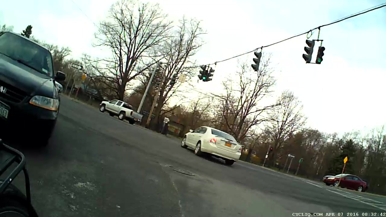
    T = 8.383 – The only clear area lies directly ahead of the oncoming silver car:

    Rt 9 Locust Grove - Right on Red - front camera - 0638
    Rt 9 Locust Grove – Right on Red – front camera – 0638

    T = 9.000 – I’m approaching the yellow line, probably won’t sideswipe the silver car, and the black car is now braking:

    Rt 9 Locust Grove - Right on Red - front camera - 0675
    Rt 9 Locust Grove – Right on Red – front camera – 0675

    T = 9.583 – The black car has nearly stopped:

    Rt 9 Locust Grove - Right on Red - front camera - 0710
    Rt 9 Locust Grove – Right on Red – front camera – 0710

    The wide-angle lens on the HDR-AS30V makes it look like I had plenty of room. The Fly6 rear camera shows why I had reason for concern:

    Rt 9 Locust Grove - Right on Red - rear camera - 0323
    Rt 9 Locust Grove – Right on Red – rear camera – 0323

    I’m still moving, the black car is slowing:

    Rt 9 Locust Grove - Right on Red - rear camera - 0332
    Rt 9 Locust Grove – Right on Red – rear camera – 0332

    T = 9.767 – Props to this driver for not starting quickly:

    Rt 9 Locust Grove - Right on Red - front camera - 0781
    Rt 9 Locust Grove – Right on Red – front camera – 0781

    Elapsed time: four seconds from spotting the black car not stopping in the right-turn lane.

    I moved back to the right side of the lane and continued the mission, but decided I didn’t need a jaunt across town to the rail trail before the rain set in to get my heart rate up.

  • Refrigerator Drawer Strut Tab: Now With Inserts

    A spate of cleaning put the little tab that fixed the never-sufficiently-to-be-damned strut supporting the lower refrigerator drawers into my hands:

    Refrigerator Drawer Strut - new tab in place
    Refrigerator Drawer Strut – new tab in place

    I discovered that 4-40 knurled inserts perfectly match the available space, so I drilled the 3D printed holes out to 11/16 inch (the OD of the smaller knurls) and rammed the inserts into place:

    Refrigerator Drawer Strut Tab - knurled inserts
    Refrigerator Drawer Strut Tab – knurled inserts

    No epoxy, no heat, nothing but a friction fit.

    Looks much better, ought to work just as well, and will definitely outlive the refrigerator; if I never take that thing apart again, it’ll be fine with me.

  • Filament Drive Gear Calculations

    Some equations relevant to indentations produced by a filament drive gear:

    Filament Drive Gear Indentations
    Filament Drive Gear Indentations

    For reference, the smaller indentations are 0.25 mm deep and 1.3 mm across the bottom.

    Variables:

    • d = filament (a.k.a. circle) diameter
    • r = filament radius
    • m = chord depth (inward from circle)
    • c = chord length
    • Θ = angle across chord from circle center, degrees
    • A = chord area (a.k.a. indentation face area)

    The length of the chord at the bottom of the indentation, perpendicular to the filament axis:

    c = 2 sqrt(2mr - m2)

    The chord angle:

    Θ = 2 arcsin(c/2r)

    The chord area, which would be the indentation face if it were perpendicular, which it isn’t:

    A = (r2 / 2) x ((πΘ / 180) - sin(Θ))

    If you measured Θ in radians, the π/180 factor would Go Away.

    Some doodles showing that reducing the indentation from 0.25 to 0.15 reduces the chord area by a factor of two:

    Filament Drive Gear - indentation doodles
    Filament Drive Gear – indentation doodles

    The implication being that you must maintain fairly constant force on the drive bearing against the filament to prevent stripping the indentations.

  • M2 Platform Alignment Check

    Five single-thread thinwall boxes scattered across the platform had an average height of  2.99 mm, with a range of +0.04 mm, -0.06 mm:

    Thinwall open box - 1 thread walls
    Thinwall open box – 1 thread walls

    The wall widths work out to 0.39 mm, with a range of +0.2 mm, -0.01 mm.

    Close enough, given that I can’t recall the last time I tweaked the platform height. I update the filament diameter setting in Slic3r every now & again as the printer gradually works through the spool, but, with one exception, this cyan PETG has been quite consistent and my tweaks didn’t really amount to much.

    Frankly, given that any of the measurements may be off by ±0.02, the best I can hope for is an overall warm fuzzy feeling. When the printed results stop looking good, these results will (probably) provide some indication of whatever just changed.

    The raw measurement data, such as it is:

    Thinwall box measurements - 2016-04-01
    Thinwall box measurements – 2016-04-01
  • Thinwall and Solid Boxes for 3D Printer Calibration

    A revision to my Fundamental Calibration Object adds some variations …

    The classic thinwall open box:

    Calibration Box - open - 1 thread - solid model
    Calibration Box – open – 1 thread – solid model

    A solid box:

    Calibration Box - solid - solid model
    Calibration Box – solid – solid model

    A solid box with text embossed on the lower surface:

    Calibration Box - solid text - solid model
    Calibration Box – solid text – solid model

    You must consider how the slicer settings interact with the solid model parameters, particularly now that slicers can produce adaptive infill for small gaps between perimeter threads. Previewing the slicer’s output will show you what assumptions it makes and prevent surprising results out there on the platform.

    A single-thread wall comes out properly:

    Thinwall open box - 0.40 wall - Slic3r
    Thinwall open box – 0.40 wall – Slic3r

    The results look just like the preview, with firmly bonded layers and no fluff:

    Thinwall open box - 1 thread walls
    Thinwall open box – 1 thread walls

    This wall should be two threads wide, but Slic3r inserts very very thin infill thread:

    Thinwall open box - 0.80 wall - Slic3r
    Thinwall open box – 0.80 wall – Slic3r

    I think that’s a result of forcing the two perimeter threads to sit with their centers exactly one thread width apart, making the (nominal, ideal) inner walls tangent to each other.  Setting the wall to 1.9 mm eliminates the hair-fine infill thread, at the cost of producing an object 0.1 mm smaller than it looks.

    Unfortunately, that fine infill doesn’t produce enough plastic flow for a continuous thread. The PET I’m using accumulates on the nozzle until enough of a glob forms to stick on the previous layer, but hair-fine strands connect those globs to each other and the nozzle, producing awful results:

    Thinwall open box - 2 thread walls
    Thinwall open box – 2 thread walls

    A triple-thread wall allows Slic3r to produce a fatter infill thread that works the way you’d expect:

    Thinwall open box - 1.20 wall - Slic3r
    Thinwall open box – 1.20 wall – Slic3r

    The threads bond firmly in all directions:

    Thinwall open box - 3 thread walls
    Thinwall open box – 3 thread walls

    It’s not obvious from that picture, but the bond between successive infill threads produces a glass-clear vertical plastic slab that relays images from the bottom to the top. The perimeter threads are also firmly bonded, albeit with not quite the same optical quality.

    To use these boxes:

    • Set the OpenSCAD extrusion parameters to match whatever the slicer will use
    • Set the wall height and thickness to whatever you like
    • Compile-and-render, export the result as a solid model in STL / AMF / whatever
    • Feed the solid model into your favorite slicer and save the G-Code
    • Feed the G-Code into your printer, watch it magically create a little box
    • Measure the printed results and compare with the ideal settings
    • Change the slicing configuration and iterate until satisfied

    Verify these measurements before adjusting anything else:

    • Filament diameter: actual vs. nominal will be different
    • Extruder steps per millimeter: mark 100 mm on filament, extrude 100 mm, compare

    Then you can verify / adjust some finicky settings:

    • Extrusion multiplier: does the actual single wall width match slicer’s nominal value?
    • Infill density: 100% infill should perfectly fill the solid box
    • Initial Z offset: does actual height match the model setting?
    • Platform alignment: print five boxes at platform center + corners, verify heights
    • First layer adhesion: if these don’t stick, the platform has weak adhesion
    • Minimum time per layer: if the walls slump, you’re printing too fast
    • Extrusion temperature: good bonding and no delamination along any axis

    The OpenSCAD source code as a GitHub gist:

    // Simple calibration boxes
    // Thin wall open box – verify Extrusion Multiplier
    // Solid box – verify infill settings
    // Ed Nisley – KE4ZNU
    // https://softsolder.com/
    Layout = "Open"; // Open Solid
    Texting = "Text!"; // text message on solid box or empty string to suppress
    //——-
    //- Extrusion parameters must match reality!
    ThreadThick = 0.25;
    ThreadWidth = 0.40;
    Protrusion = 0.1; // make holes end cleanly
    function IntegerMultiple(Size,Unit) = Unit * ceil(Size / Unit);
    //——-
    // Dimensions
    WallThick = 1.0 * ThreadWidth;
    echo(str("Wall thickness: ",WallThick));
    BoxSize = 20.0;
    echo(str("Overall size: ",BoxSize));
    NominalHeight = 3.0;
    echo(str("Nominal height: ",NominalHeight));
    Height = IntegerMultiple(NominalHeight,ThreadThick);
    echo(str("Actual height: ",Height));
    Rotation = 0; // 45 to exercise X and Y axis motors at same time
    CornerRadius = 2.0;
    CornerSides = 8*4;
    //——–
    module Solid() {
    difference() {
    hull()
    for (i=[-1,1], j=[-1,1])
    translate([i*(BoxSize – 2*CornerRadius)/2,j*(BoxSize – 2*CornerRadius)/2,0])
    cylinder(r=CornerRadius,h=Height,$fn=CornerSides);
    if (len(Texting))
    translate([0,0,-Protrusion/2])
    linear_extrude(height=3*ThreadThick + Protrusion)
    mirror([1,0,0])
    text(text=Texting,size=6,spacing=1.05,font="ITC Zapf Chancery:style=Italic",halign="center",valign="center");
    }
    }
    module Thinwall() {
    difference() {
    Solid();
    hull()
    for (i=[-1,1], j=[-1,1])
    translate([i*(BoxSize – 2*CornerRadius)/2,j*(BoxSize – 2*CornerRadius)/2,-Protrusion])
    cylinder(r=(CornerRadius – WallThick),h=(Height + 2*Protrusion),$fn=CornerSides);
    }
    }
    //——-
    rotate(Rotation)
    if (Layout == "Open")
    Thinwall();
    else
    Solid();
  • Road Conditions: 2816 Rt 376 Northbound Sinkhole

    We must dodge this sinkhole on every northbound ride, which means about four times a week:

    Rt 376 2016-01-15 - Northbound milepost 1110 - sinkhole
    Rt 376 2016-01-15 – Northbound milepost 1110 – sinkhole

    It’s been sinking, month by month, ever since I reported it to NYSDOT last July. They dispatched a work crew that did a remarkable job of patching everything around the sinkhole (note the asphalt obliterating the center line), but somehow missed the actual hole on the shoulder, despite the picture I sent. Just before snow season, a second crew patched many small holes along Rt 376 from Red Oaks Mill to Hooker Avenue, but, once again, missed this one.

    If it doesn’t look like much, let’s go for a check ride.

    This section of Rt 376 forms part of NYS Bike Route 9.

  • Road Conditions: Drain Grates on Vassar Road near Red Oaks Mill

    Apart from having a wheel-catcher grid, this one seems survivable:

    Drain grate 1 - 43 Vassar Rd
    Drain grate 1 – 43 Vassar Rd

    You can avoid it as long as you stay alert.

    This beauty, however, stops cars dead in their tracks:

    Drain grate 2 - 35 Vassar Rd
    Drain grate 2 – 35 Vassar Rd

    Drivers who pass cars making a left turn into the strip mall on the other side slam to a stop if they’re lucky enough to see that crater before it claims their right front tire; the grid is about a foot down from grade. The scrapes and scuffs on the far side show that, if it wasn’t for bad luck, some folks wouldn’t have no luck at all.

    Obviously, you can’t bicycle through that one.

    This grate, directly across Vassar Road, would count as a serious pothole in any other context:

    Drain grate 3 - 40 Vassar Rd
    Drain grate 3 – 40 Vassar Rd

    The pavement remains in better shape, because it’s just to the left of the strip mall entrance, but, again, the grate is about a foot below grade. Those scrapes on the far side suggest some folks didn’t notice that in time.

    If I rode any further to the right, perhaps just on the other side of the fog line, my wheels would be on the steep slope from the fog line down to the grid. It’s survivable as long as you expect it and keep a tight grip on the handlebars.

    Vassar Road, formally known as Dutchess County Route 77, forms part of NYS Bike Route 9.