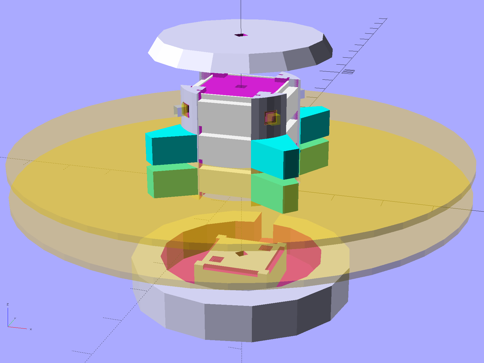
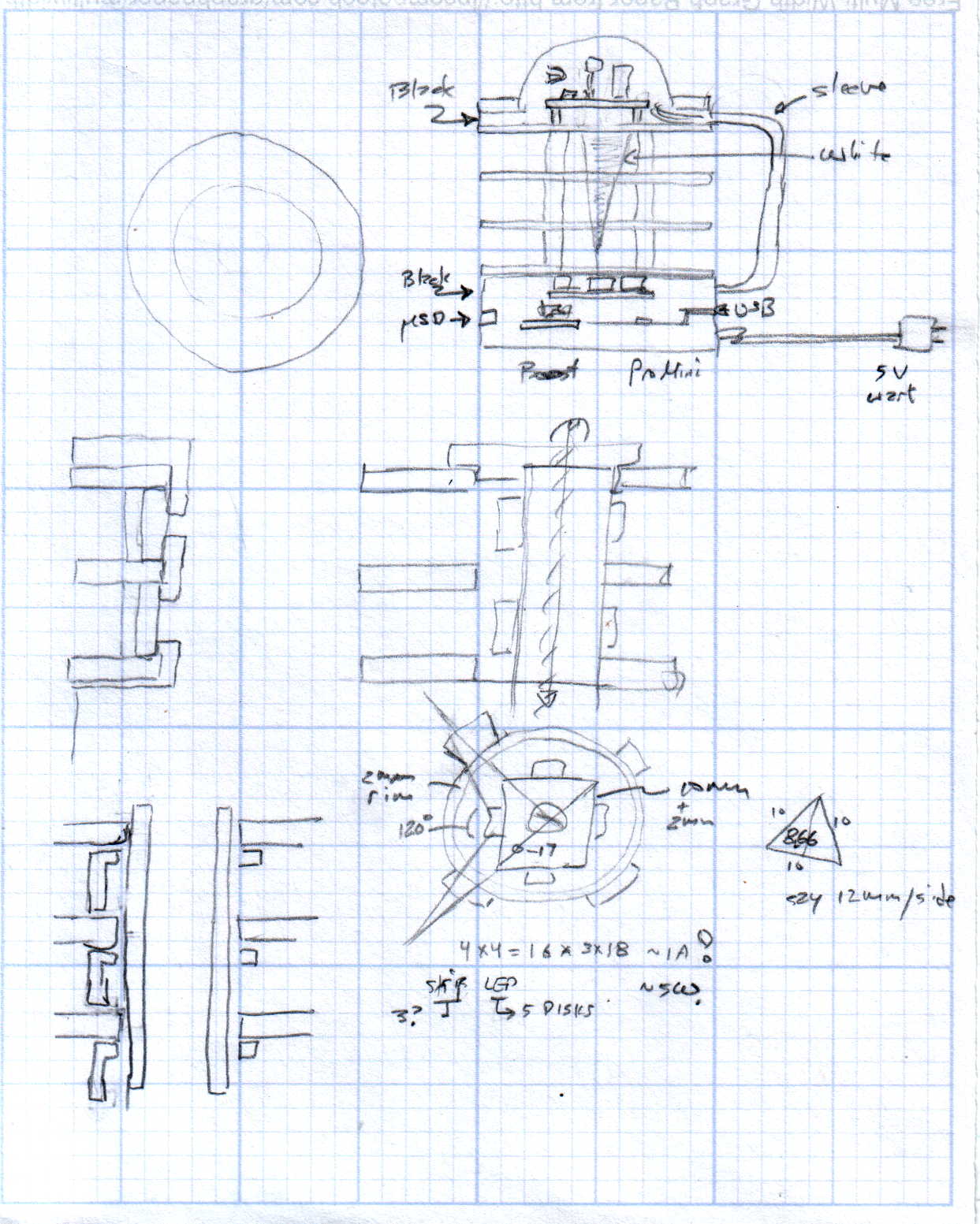
Harvesting a stack of hard drive platters and discovering that four Neopixel strips could stand vertically inside the central hole suggested this overall structure:
The model includes a parameter for the number of strips, but not everything respects that. I’m not sure I’ll ever make a three-LED column and five strips won’t fit, so it probably doesn’t matter.
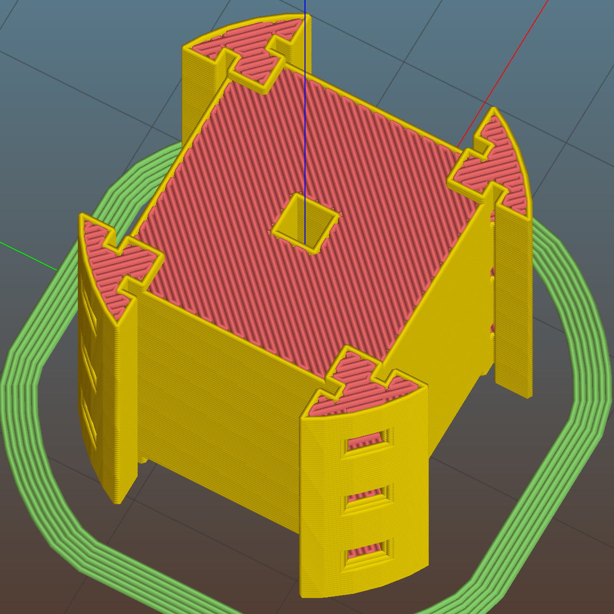
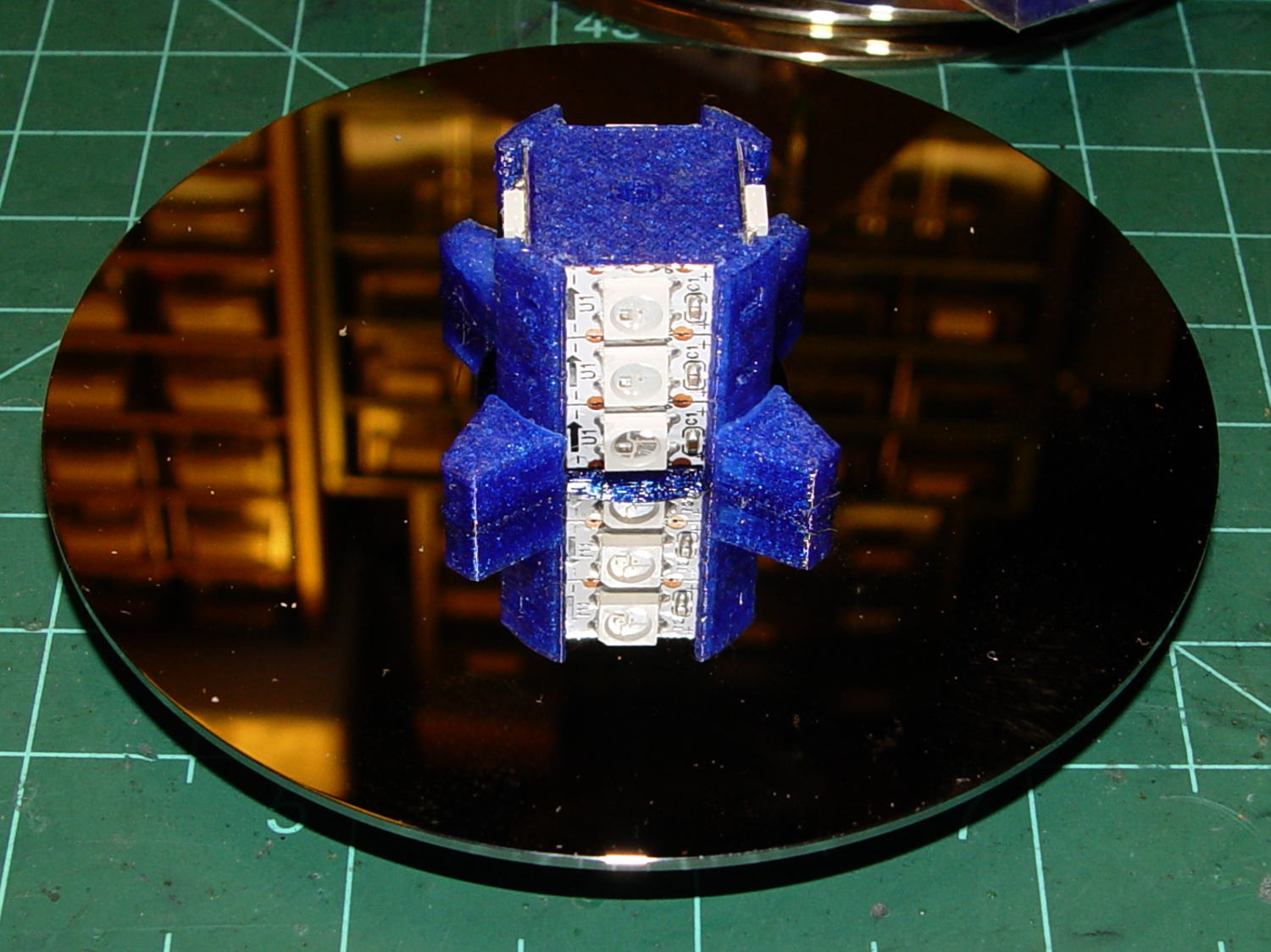
The central pillar holds everything together:

The Neopixel strips slide into those slots, which turned out to be too small to actually print, because the molten plastic pretty much squeezed the slots closed. Some deft pull saw action enlarged them enough to pass the strips, at the cost of tedious hand-fitting and considerable hidden ugliness. Printing the slots slightly larger bangs against the (lack of) printer resolution, because there’s not much wiggle room between the tiny slots and the outer diameter of the column:
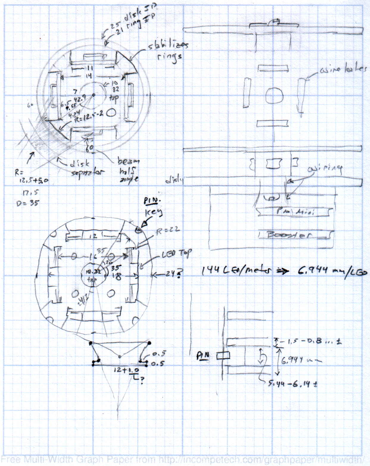
The three alignment pin holes along each edge sit 6.944 mm on center, which is what you get when you divide the nominal 1 meter strip length by 144 Neopixels. I’m using knockoff Neopixels from halfway around the planet, but they’re probably pretty close to the real thing (also from halfway around the planet, I’m sure).
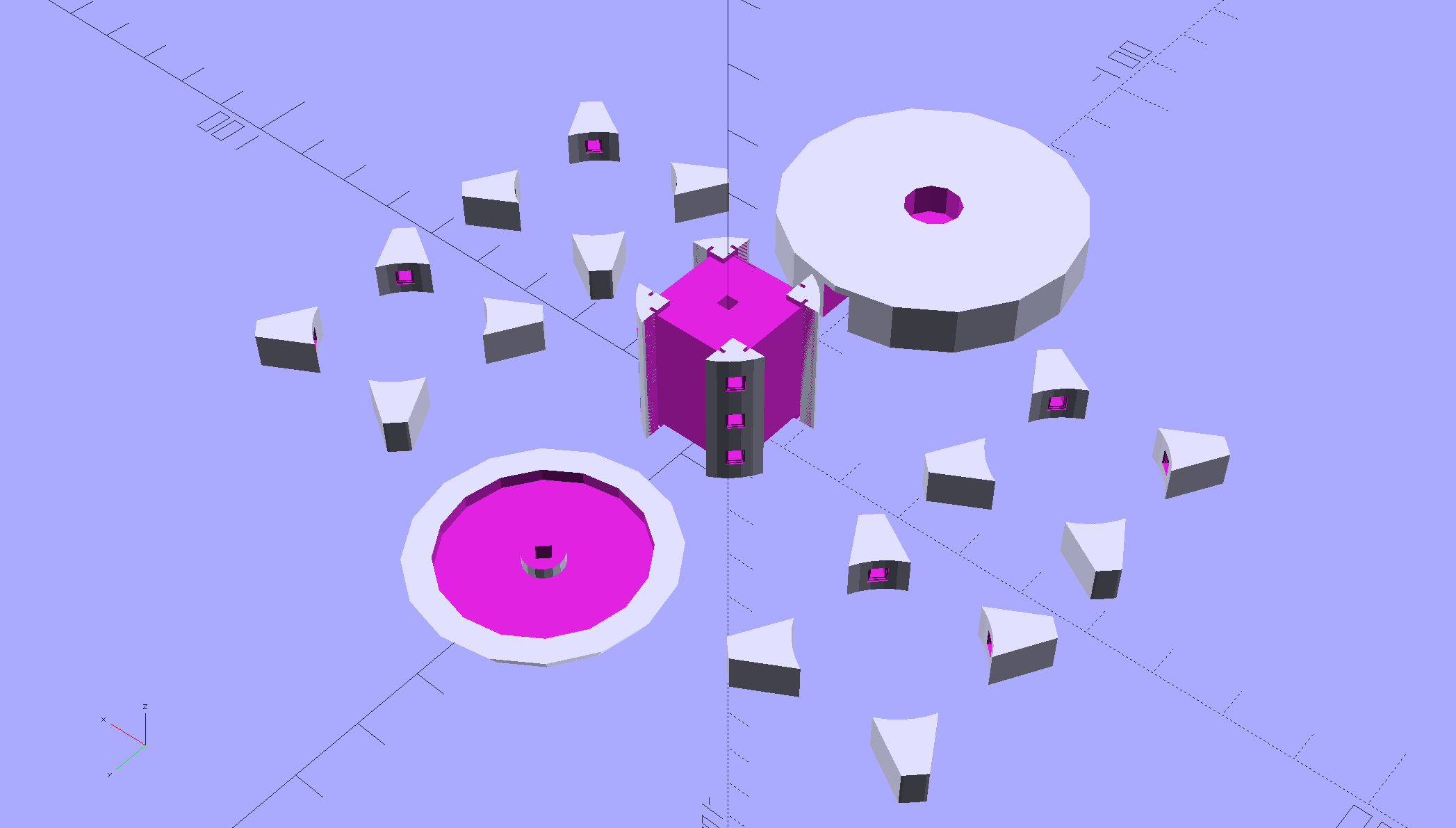
All those parts laid out on the platform, along with a fourth set of spacers in case I drop one:
And they print in cyan PETG just like you’d expect:
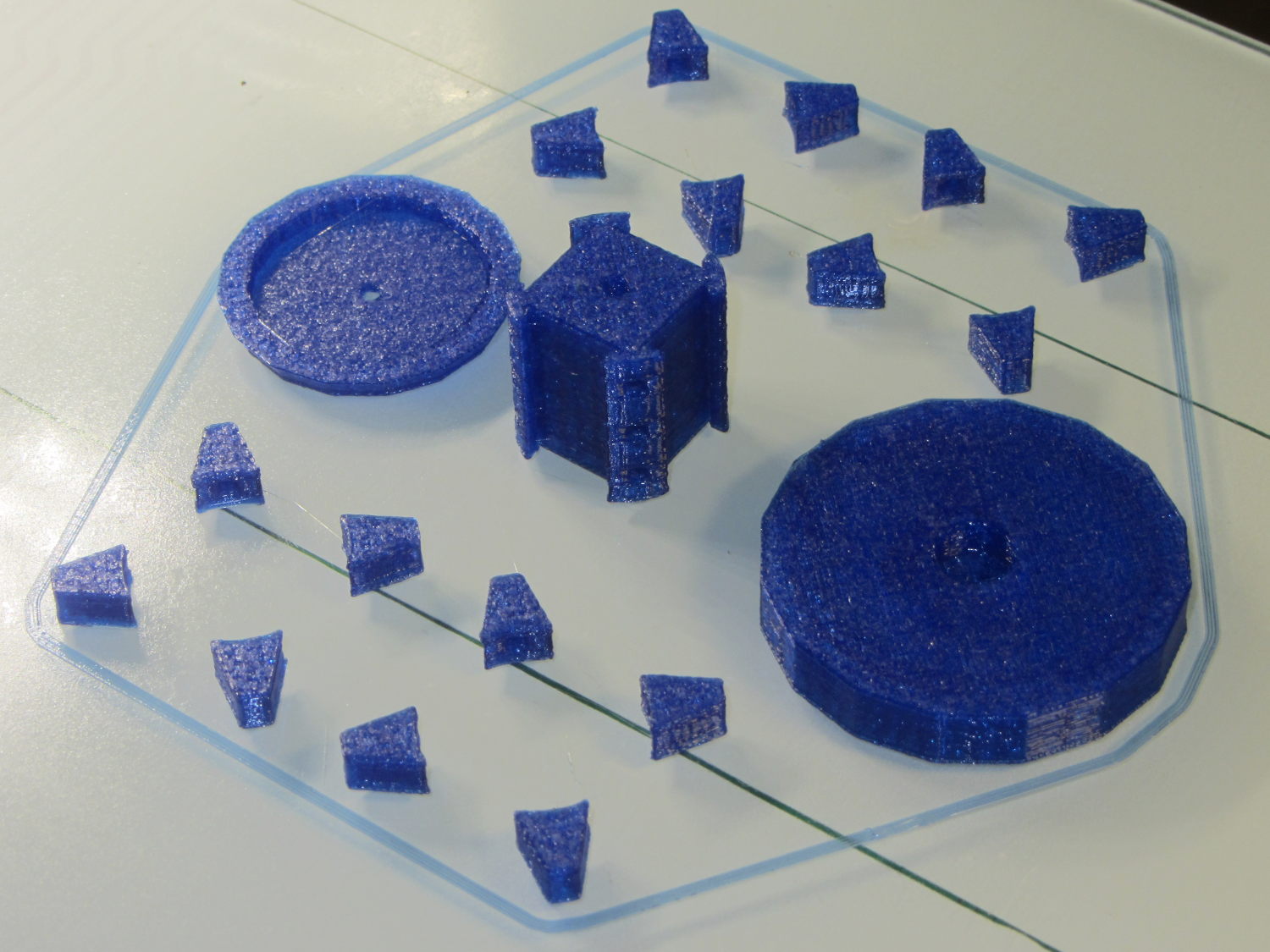
The round base (on the right) prints bottom-side-up, with bridging from the rim to the central pillar, and came out looking just fine. The top doesn’t have the central post and the pillar doesn’t have the top recess shown in the model: those tweaks will appear in the next iteration.
Each tiny triangular spacer gets an alignment pin glued into its inner surface, then four of them get glued to the pillar. This crash test dummy pillar worked out the dimensions, so it’s squat and ugly:
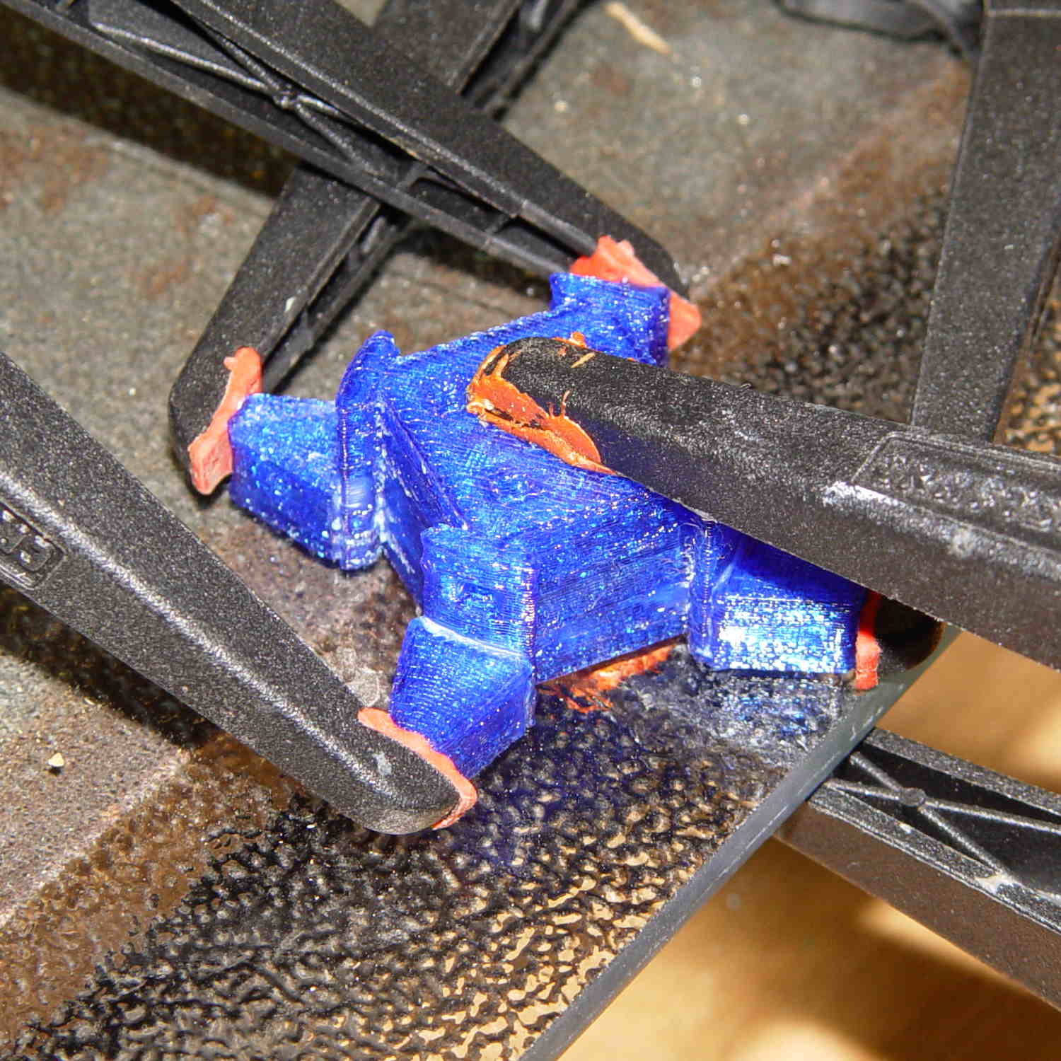
It’s clamped to a glass plate (smooth side up!) to force the spacers onto on a plane, with the other clamps smashing them against the pillar. All the other spacers get glued in situ atop each platter as it’s installed, which is a definite downside.
Installing the Neopixels before assembling the platters seemed to be the right way to go:
After that, just stack ’em up:
I dry-assembled the upper two spacer sets, so I could pull it apart in case that seemed necessary. Turned out to be a good idea.
And then screw the lid on top to see what it looks like:

That top screw should be a pan-head or something similarly smooth, rather than a random PC case screw. The sacrificial hard drives provided a bunch of Torx screws that would surely look better; most are far too small.
I thought a taller stack would be appropriate, but I kinda like the short, squat aspect ratio.
Now for some wiring…
The OpenSCAD source code:
// Hard Drive Platter Mood Light
// Ed Nisley KE4ZNU November 2015

Layout = "Show";					// Build Show Pixel LEDString Platters Pillar Spacers TopCap Base

ShowDisks = 2;						// number of disks in Show layout

//- Extrusion parameters must match reality!

ThreadThick = 0.20;
ThreadWidth = 0.40;

HoleWindage = 0.2;

Protrusion = 0.1;			// make holes end cleanly

inch = 25.4;

function IntegerMultiple(Size,Unit) = Unit * ceil(Size / Unit);

//----------------------
// Dimensions

ID = 0;
OD = 1;
LENGTH = 2;

Platter = [25.0,95.0,1.27];						// hard drive platters

LEDStringCount = 3;								// number of LEDs on each strip (Show mode looks odd for less than 3)
LEDStripCount = 4;								// number of strips (verify locating pin holes & suchlike)

WireSpace = 1.0;								// allowance for wiring along strip ends

BaseSize = [40,14,3.0];							// overall base plate outside engine controller slot

Pixel = [13.0, 1000 / 144, 0.5];				// smallest indivisible unit of LED strip
PixelMargin = [1.0, 1.0, 2.0];					// LED and circuitry atop the strip

BeamAngle = 120;								// LED viewing angle
BeamShape = [
	[0,0],
	[Platter[OD]*cos(BeamAngle/2),-Platter[OD]*sin(BeamAngle/2)],
	[Platter[OD]*cos(BeamAngle/2), Platter[OD]*sin(BeamAngle/2)]
];

PillarSides = 12*4;

PillarCore = Platter[ID] - 2*(Pixel[2] + PixelMargin[2] + 2.0);		// LED channel distance across pillar centerline
PillarLength = LEDStringCount*Pixel[1] + Platter[LENGTH];
echo(str("Pillar core size: ",PillarCore));
echo(str("      ... length:"),PillarLength);

Cap = [Platter[ID] + 4.0,Platter[ID] + 4.0 + 10*2*ThreadWidth,2*WireSpace + 6*ThreadThick];		// cap over top of pillar
CapSides = 16;

Base = [Platter[ID] + 10.0,0.5*Platter[OD],8.0];
BaseSides = 16;

Screw = [2.0,3.0,20.0];							// screws used to secure cap & pillar

Spacer = [Platter[ID],(Platter[ID] + 2*8),(Pixel[1] - Platter[LENGTH])];
echo(str("Spacer  OD: ",Spacer[OD]));
echo(str(" ... thick:",Spacer[LENGTH]));

LEDStripProfile = [
	[0,0],
	[Pixel[0]/2,0],
	[Pixel[0]/2,Pixel[2]],
	[(Pixel[0]/2 - PixelMargin[0]),Pixel[2]],
	[(Pixel[0]/2 - PixelMargin[0]),(Pixel[2] + PixelMargin[2])],
	[-(Pixel[0]/2 - PixelMargin[0]),(Pixel[2] + PixelMargin[2])],
	[-(Pixel[0]/2 - PixelMargin[0]),Pixel[2]],
	[-Pixel[0]/2,Pixel[2]],
	[-Pixel[0]/2,0]
];

//----------------------
// Useful routines

module PolyCyl(Dia,Height,ForceSides=0) {			// based on nophead's polyholes

  Sides = (ForceSides != 0) ? ForceSides : (ceil(Dia) + 2);

  FixDia = Dia / cos(180/Sides);

  cylinder(r=(FixDia + HoleWindage)/2,
		h=Height,
	$fn=Sides);
}

//- Locating pin hole with glue recess
//  Default length is two pin diameters on each side of the split

PinOD = 1.70;

module LocatingPin(Dia=PinOD,Len=0.0) {

	PinLen = (Len != 0.0) ? Len : (4*Dia);

	translate([0,0,-ThreadThick])
		PolyCyl((Dia + 2*ThreadWidth),2*ThreadThick,4);

	translate([0,0,-2*ThreadThick])
		PolyCyl((Dia + 1*ThreadWidth),4*ThreadThick,4);

	translate([0,0,-(PinLen/2 + ThreadThick)])
		PolyCyl(Dia,(PinLen + 2*ThreadThick),4);

}
//----------------------
// Pieces

//-- LED strips

module OnePixel() {

	render()
		rotate([-90,0,0]) rotate(180)				// align result the way you'd expect from the dimensions
			difference() {
				linear_extrude(height=Pixel[1],convexity=3)
					polygon(points=LEDStripProfile);
				translate([-Pixel[0]/2,Pixel[2],-PixelMargin[0]])
					cube([Pixel[0],2*PixelMargin[2],2*PixelMargin[0]]);
				translate([-Pixel[0]/2,Pixel[2],Pixel[1]-PixelMargin[0]])
					cube([Pixel[0],2*PixelMargin[2],2*PixelMargin[0]]);
			}
}

module LEDString(n = LEDStringCount) {

	for (i=[0:n-1])
		translate([0,i*Pixel[1]])
//			resize([0,Pixel[1] + 2*Protrusion,0])
				OnePixel();
}

//-- Stack of hard drive platters

module Platters(n = LEDStringCount + 1) {

	color("gold",0.4)
	for (i=[0:n-1]) {
		translate([0,0,i*Pixel[1]])
			difference() {
				cylinder(d=Platter[OD],h=Platter[LENGTH],center=false,$fn=PillarSides);
				cylinder(d=Platter[ID],h=3*Platter[LENGTH],center=true,$fn=PillarSides);
			}
	}
}

//-- Pillar holding the LED strips

module Pillar() {

	difflen = PillarLength + 2*Protrusion;

//	render(convexity=5)
	difference() {
		linear_extrude(height=PillarLength,convexity=4)
			difference() {
				rotate(180/(12*4))
					circle(d=Platter[ID] - 1*ThreadWidth,$fn=PillarSides);

				for (i=[0:LEDStripCount-1]) 					// clearance for LED beamwidth, may not actually cut surface
					rotate(i*360/LEDStripCount)
						translate([PillarCore/2,0,0])
							polygon(points=BeamShape);

				for (i=[0:LEDStripCount-1])						// LED front clearance
					rotate(i*360/LEDStripCount)
						translate([(PillarCore/2 + Pixel[2]),(Pixel[0] - 2*PixelMargin[0])/2])
							rotate(-90)
								square([Pixel[0] - 2*PixelMargin[0],Platter[ID]]);

			}

		for (i=[0:LEDStripCount-1])								// LED strip slots
			rotate(i*360/LEDStripCount)
				translate([PillarCore/2,0,-Protrusion])
					linear_extrude(height=difflen,convexity=2)
						rotate(-90)
							polygon(points=LEDStripProfile);

		for (i=[0,90])											// wiring recess on top surface
			rotate(i)
				translate([0,0,(PillarLength - (WireSpace/2 - Protrusion))])
					cube([(PillarCore + 2*Protrusion),Pixel[0] - 2*PixelMargin[0],WireSpace],center=true);

		for (i=[0:LEDStripCount-1])								// wiring recess on bottom surface
			rotate(i*90)
				translate([PillarCore/2 - (WireSpace - Protrusion)/2,0,WireSpace/2 - Protrusion])
					cube([WireSpace + Protrusion,Pixel[0] - 2*PixelMargin[0],WireSpace],center=true);

		for (j=[0:LEDStringCount-1])							// platter spacer alignment pins
			for (i=[0:LEDStripCount-1])
				rotate(i*360/LEDStripCount + 180/LEDStripCount)
					translate([(Platter[ID] - 1*ThreadWidth)/2,0,(j*Pixel[1] + Pixel[1]/2 + Platter[LENGTH]/2)])
						rotate([0,90,0])
							rotate(45)
								LocatingPin();

		translate([0,0,-Protrusion])							// central screw hole
			rotate(180/4)
				PolyCyl(Screw[ID],difflen,4);

		if (false)
		for (i=[-1,1])											// vertical wire channels
			rotate(i*360/LEDStripCount + 180/LEDStripCount)
				translate([PillarCore/2 - 2.0,0,-Protrusion])
					PolyCyl(2.0,difflen,4);

		for (i=[-1,1])											// locating pins
			rotate(i*360/LEDStripCount - 180/LEDStripCount)
				translate([PillarCore/2 - 2.0,0,0])
					LocatingPin();
	}
}

//-- Spacers to separate platters

module Spacers() {

	difference() {
		linear_extrude(height=Spacer[LENGTH],convexity=4)
			difference() {
				rotate(180/PillarSides)
					circle(d=Spacer[OD],$fn=PillarSides);

				for (i=[0:LEDStripCount-1]) 					// clearance for LED beamwidth, may not actually cut surface
					rotate(i*360/LEDStripCount)
						translate([PillarCore/2,0,0])
							polygon(points=BeamShape);

				for (i=[0:LEDStripCount-1])						// LED front clearance
					rotate(i*360/LEDStripCount)
						translate([(PillarCore/2 + Pixel[2]),(Pixel[0] - 2*PixelMargin[0])/2])
							rotate(-90)
								square([Pixel[0] - 2*PixelMargin[0],Platter[ID]]);


				rotate(180/PillarSides)
					circle(d=Spacer[ID],$fn=PillarSides);		// central pillar fits in the hole
			}

		for (i=[0:LEDStripCount-1])
			rotate(i*360/LEDStripCount + 180/LEDStripCount)
				translate([Platter[ID]/2,0,(Pixel[1] - Platter[LENGTH])/2])
					rotate([0,90,0])
						rotate(45)
							LocatingPin();

	}
}

//-- Cap over top of pillar

module TopCap() {

	difference() {
		cylinder(d1=(Cap[OD] + Cap[ID])/2,d2=Cap[OD],h=Cap[LENGTH],$fn=CapSides);		// outer lid

		translate([0,0,-Protrusion])
			PolyCyl(Screw[ID],Cap[LENGTH] + WireSpace + Protrusion,4);					// screw hole

		translate([0,0,Cap[LENGTH] - 2*WireSpace])
			difference() {
				cylinder(d=Cap[ID],h=2*Cap[LENGTH],$fn=CapSides);						// cutout
				cylinder(d=2*Screw[OD],h=Cap[LENGTH],$fn=CapSides);						// boss
			}

		translate([0,0,Cap[LENGTH] - ThreadThick])
			cylinder(d=Cap[ID]/2,h=ThreadThick + Protrusion,$fn=CapSides);				// recess boss
	}
}

//-- Base below pillar

module Base() {

	SideWidth = 0.5*Base[OD]*sin(180/BaseSides);						// close enough

	difference() {
		union() {
			difference() {
				cylinder(d=Base[OD],h=Base[LENGTH],$fn=BaseSides);			// outer base

				translate([0,0,6*ThreadThick])								// main cutout
					cylinder(d=Base[ID],h=Base[LENGTH],$fn=BaseSides);

				translate([-SideWidth/2,0,6*ThreadThick]) 					// cable port
					cube([SideWidth,Base[OD],Base[LENGTH]]);
			}

			translate([0,0,Base[LENGTH]/2])									// pillar support is recessed below rim
				cube([PillarCore,PillarCore,Base[LENGTH] - ThreadThick],center=true);
		}

		for (i=[0:LEDStripCount-1])											// wiring recesses
			rotate(i*90)
				translate([PillarCore/2 - (WireSpace - Protrusion)/2,0,Base[LENGTH] - WireSpace/2])
					cube([WireSpace + Protrusion,PillarCore - 4*WireSpace,WireSpace],center=true);

		translate([0,0,-Protrusion])
			PolyCyl(Screw[ID],2*Base[LENGTH],4);						// screw hole

		translate([0,0,-Protrusion])									// screw head recess
			PolyCyl(8.5,5.0 + Protrusion,$fn=6);

		for (i=[-1,1])													// locating pins
			rotate(i*360/LEDStripCount - 180/LEDStripCount)
				translate([PillarCore/2 - 2.0,0,Base[LENGTH] - ThreadThick])
					LocatingPin();

	}

}

//----------------------
// Build it

if (Layout == "Pixel")
	OnePixel();

if (Layout == "LEDString")
	LEDString(LEDStringCount);

if (Layout == "Platters")
	Platters(LEDStringCount + 1);

if (Layout == "Pillar")
	Pillar(LEDStringCount);

if (Layout == "TopCap")
	TopCap();

if (Layout == "Base")
	Base();

if (Layout == "Spacers")
	Spacers();

if (Layout == "Show") {
	Pillar();

	for (i=[0:LEDStripCount-1])											// LED strips
		rotate(i*360/LEDStripCount)
			translate([PillarCore/2,0,Platter[LENGTH]/2])
				rotate([90,0,90])
					color("lightblue") LEDString();
	if (true)
	for (j=[0:max(1,ShowDisks - 2)])									// spacers
		translate([0,0,(j*Pixel[1] + Platter[LENGTH])])
			color("cyan") Spacers();

	for (j=[0:max(2,ShowDisks - 2)])										// spacer alignment pins
		for (i=[0:LEDStripCount-1])
			rotate(i*360/LEDStripCount + 180/LEDStripCount)
				translate([(Platter[ID] - 1*ThreadWidth)/2,0,(j*Pixel[1] + Pixel[1]/2 + Platter[LENGTH]/2)])
					rotate([0,90,0])
						rotate(45)
							 color("Yellow",0.25) LocatingPin(Len=4);
	translate([0,0,PillarLength + 3*Cap[LENGTH]])
		rotate([180,0,0])
			TopCap();

	translate([0,0,-3*Base[LENGTH]])
		Base();

	if (ShowDisks > 0)
		Platters(ShowDisks);

}

// Ad-hoc build layout

if (Layout == "Build") {
	Pillar();

	translate([0,Cap[OD],0])
		TopCap();

	translate([0,-Base[OD],Base[LENGTH]])
		rotate([0,180,0])
			Base();

	Ybase = Spacer[OD] * (LEDStringCount%2 ? (LEDStringCount - 1) : (LEDStringCount - 2)) / 4;
	for (i=[0:LEDStringCount])										// build one extra set of spacers!
		translate([(i%2 ? 1 : -1)*(Spacer[OD] + Base[OD])/2,		// alternate X sides to shrink Y space
				   (i%2 ? i-1 : i)*Spacer[OD]/2 - Ybase,			// same Y for even-odd pairs in X
				   0])
			Spacers();
}
The original doodles showing this might work, along with some ideas that wouldn’t:


Comments
5 responses to “Hard Drive Platter Mood Light: 3D Printed Structure”
Nifty. Are they going to spin? Is it going to have a slip-ring?
Nope, it’s a static display: all the electronics attach to the plastic hub that clamps the disks.
I thought about mounting the head arm off to one side and having the Arduino wave it around, but came to my senses; the disk spacing doesn’t work out neatly and it’d need those intense stator magnets.
Watching the LEDs change color is as good as it gets… [grin]
[…] thickness wouldn’t matter, except that the OpenSCAD program producing the hub & spacer tabs for the Mood Lights needs to […]
[…] Hard Drive Platter Mood Light: 3D Printed Structure New Countertop vs. Old Strut […]
[…] having glued the spacers onto the hub simplified extracting the strip, although warranty repair is always a nuisance. I daubed red […]