Ed Nisley's Blog: Shop notes, electronics, firmware, machinery, 3D printing, laser cuttery, and curiosities. Contents: 100% human thinking, 0% AI slop.
The 170° fisheye lens on the HDR-AS30V action camera protrudes from the front of the case, the better to view the passing scenery:
Sony HDR-AS30V Action Camera
Unfortunately, that means there’s nothing to protect it when the scenery gets a bit too close.
Mounting it upside-down in the skeleton frame provides a bit of protection, by putting it inside the straight line connecting the helmet brim with the top of the frame:
Sony HDR-AS30V camera on bike helmet – inverted
That won’t protect it from severe impacts, but perhaps a casual drop won’t scar the lens. You can tell from the scuffs that the helmet does get dropped every now and then.
When you remove the skeleton mount from the helmet, grip the camera between finger and thumb while releasing the latch with your other hand. The mount will dangle from your fingers and the camera won’t slide out; if you don’t have both hands free, don’t mess with the camera.
Even though it doesn’t look at all like a GoPro Hero, everybody recognizes the “camera on helmet” meme and, in general, behaves a bit more circumspectly. I didn’t see that coming, not at all.
This doesn’t happen very often, but, after a few road trips and some jostling around, the M2’s platform was definitely out of alignment: the first layer came out generally too thin, with the X-Y+ quadrant very much too thin.
I tried a quick and dirty adjustment that didn’t produce meaningful results, then broke out the Starrett Taper Gauge and did it right.
Jog around measuring the height of the nozzle above the platform
Adjust screws to reduce variation
Change Z offset in startup G-Code
Run off a few test patterns to get the platform heated
Measure actual thickness
Change Z offset to get the right answer
Done!
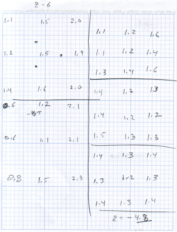
This progression of cold measurements, read top-to-bottom, left column first, shows the observed nozzle height above the platform around the edges and at the center:
M2 Platform Leveling Progression – 2014-06-30
The final measurements seem to indicate the glass plate is 0.2 mm convex in the center, but I wouldn’t trust the measurements to that level of accuracy. It’s probably bowed upward, but it’s certainly close enough.
The cold measurements suggest that the Z offset should be -4.80 mm, but the measurements on the hot platform with actual extrusion threads showed that -4.50 mm produced the correct thicknesses.
It’s not clear automating the movements would produce better or faster results than just manually jogging the nozzle around the platform, particularly since it happens only every few months.
This would be easier with the Z offset stored in the EEPROM and some modified startup G-Code to retrieve it.
Much of the boat traffic on the Hudson consists of barges shuttling bulk commodities between the Atlantic and the Port of Albany. I think this is a crude oil barge, based on the Christmas Tree plumbing that was more visible when it passed under the Mid Hudson Bridge:
Walkway and Barge – from Mid Hudson Bridge
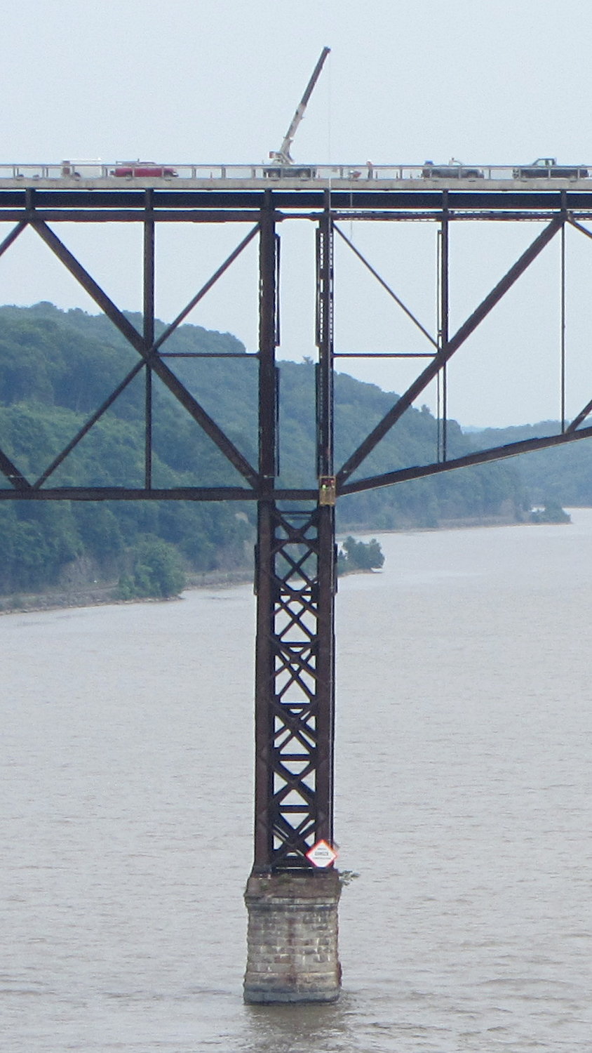
We crossed the Walkway Over the Hudson westbound, where a work crew was tending a crane. That’s how they do repair and inspection:
Walkway Inspection Crane – from Mid Hudson Bridge
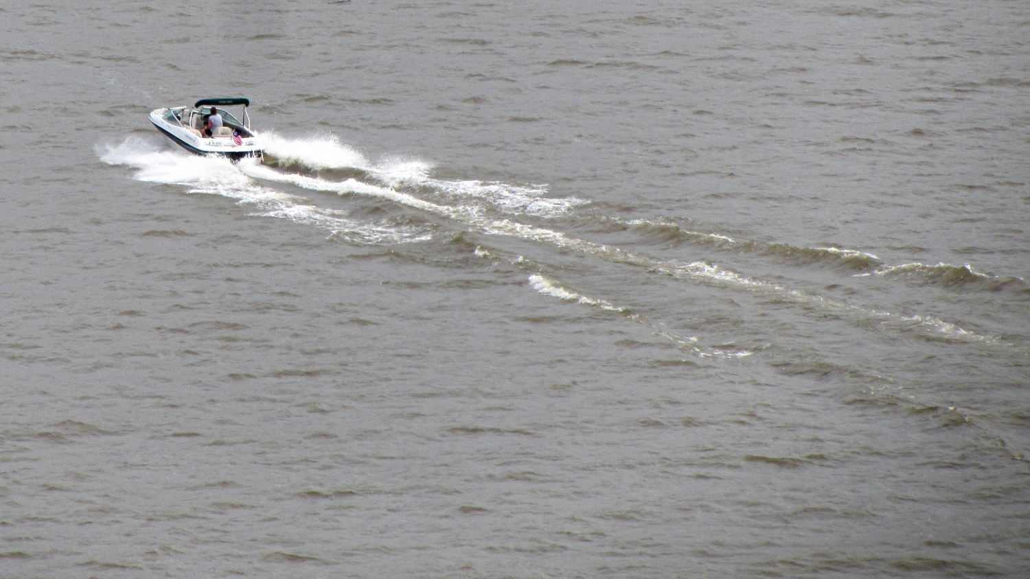
The Hudson River has far fewer power boats than in years gone by, probably due to their gallon-per-minute fuel consumption:
Power boat on Hudson River – from Mid Hudson Bridge
It turns out that the clever idea of moving the swap partition to a USB flash drive had no effect whatsoever; the UI continued to freeze up during OpenSCAD compiles and suchlike, with the drive activity light on solid and not much in the way of swap activity. Sooo, I wondered what would happen with the /tmp directory on non-rotating memory.
Then I spotted a sale on a Samsung 840 EVO 120 GB solid state drive, which seemed like it might improve almost everything in one swell foop. That’s a tiny drive, at least by contemporary standards, but all my data files live downstairs on the file server, so the desktop drive holds just the Xubuntu installation.
It’s worth noting that SSDs tend to fail suddenly and catastrophically, so that if the only copy of your data is on that drive, there is no recovery. In this case, I’d lose some configuration that changes with every installation, a few locally installed / compiled-from-source programs, and little else.
The nice thing about transferring a Linux installation: boot a live CD image (I used Ubuntu 14.04LTS, the same as the desktop box), copy the files to the new drive, set up Grub, and you’re back on the air. That recipe worked fine, although I used rsync -au to copy the files and then updated /etc/fstab with the SSD’s new UUID (rather than duplicate a supposedly unique ID).
The Grub recipe does require a bit of delicate surgery, so I removed the OEM hard drive and rebooted the live CD image before doing this. If the SSD fell victim to a finger fumble, I could just start over again:
sudo mount /dev/sda1 /mnt
for f in dev proc sys usr ; do sudo mount --bind /$f /mnt/$f ; done
sudo chroot /mnt
sudo update-grub
sudo grub-install /dev/sda
sudo grub-install --recheck /dev/sda
exit
for f in dev proc sys usr ; do sudo umount /mnt/$f ; done
sudo umount /mnt
Then reboot from the SSD and It Just Worked.
Dropbox and DigiKam noticed the UUID change and asked for advice; there’s no need for re-registration, re-activation, or re-authorization.
The overall time from boot to login isn’t much shorter, because of the tedious delay while the network and the NFS shares get up & running, but the desktop UI startup zips right along.
The same OpenSCAD compile that previously brought the UI to a halt has no effect, so I hereby declare victory. I think the complex solid models that used to take forever will see much the same speedup.
The Dell hard drive (an ordinary 7200 RPM 3.5 inch brick) lies abandoned in place under the fancy black shroud; the Optiplex 980 layout butts the drive’s right-angle SATA connectors hard against the CPU heatsink and offers no spare SATA power connectors. There was just enough room to wedge the SSD above the PCI connectors, where it won’t get into any trouble:
Samsung 840 EVO SSD in Optiplex 980
The hard drive contains the never-used Windows 7 partition and the corresponding recovery / diagnostic partitions; keeping the drive with the Optiplex chassis seems like a Good Idea.
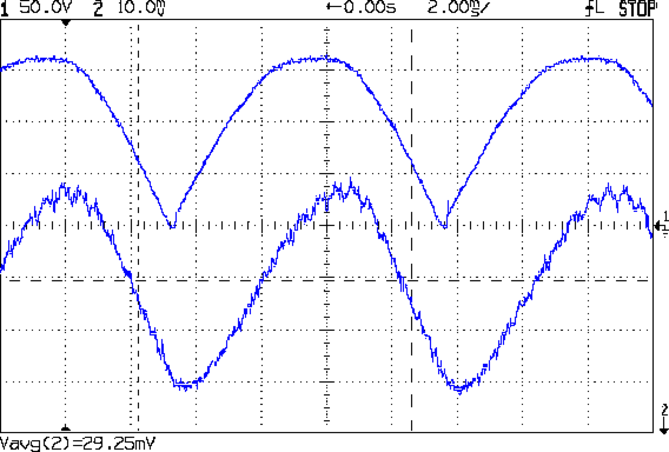
Because the universal-wound AC motorruns on DC, it will also run on full-wave rectified AC (top trace). The current waveform (bottom, 200 mA/div) never hits zero:
Rectified AC – 200 mA div – 875 RPM
Note that the current lags the voltage, as you’d expect from an inductive load.
The average current at 120 VAC rectified is about 600 mA, a bit over the current at 50 V that I measured from the DC supply while driving the sewing machine. The locked-rotor torque averages 1 A, although it’s pretty hard to hold the handwheel at full voltage.
The key advantage of rectified AC: an ordinary MOSFET can control the motor current.
Given the motor’s sensitivity to current limiting, there’s not much point in measuring the current; unlike LED brightness, the speed isn’t proportional to the current. The MOSFET must act more like the carbon pile rheostat, burning whatever voltage the motor doesn’t need to run at the selected speed, with the RPM setpoint determining the gate voltage in a closed loop.
You can detect a stall by watching the motor RPM: when that drops too far below the setpoint, it’s stalled.
The gotcha will be keeping the MOSFET within its the safe operating area at both ends of the voltage range, due to the nearly constant current at any applied voltage:
High voltage + high current hits the maximum pulsed power limit of IDSVDS
Low voltage + high current hits the minimum possible voltage of IDSRDS
I think the relatively low current and power levels will simplify that mess; offering up a sacrificial MOSFET for measurement may be in order.
On the whole, it’s looking more do-able than I thought.