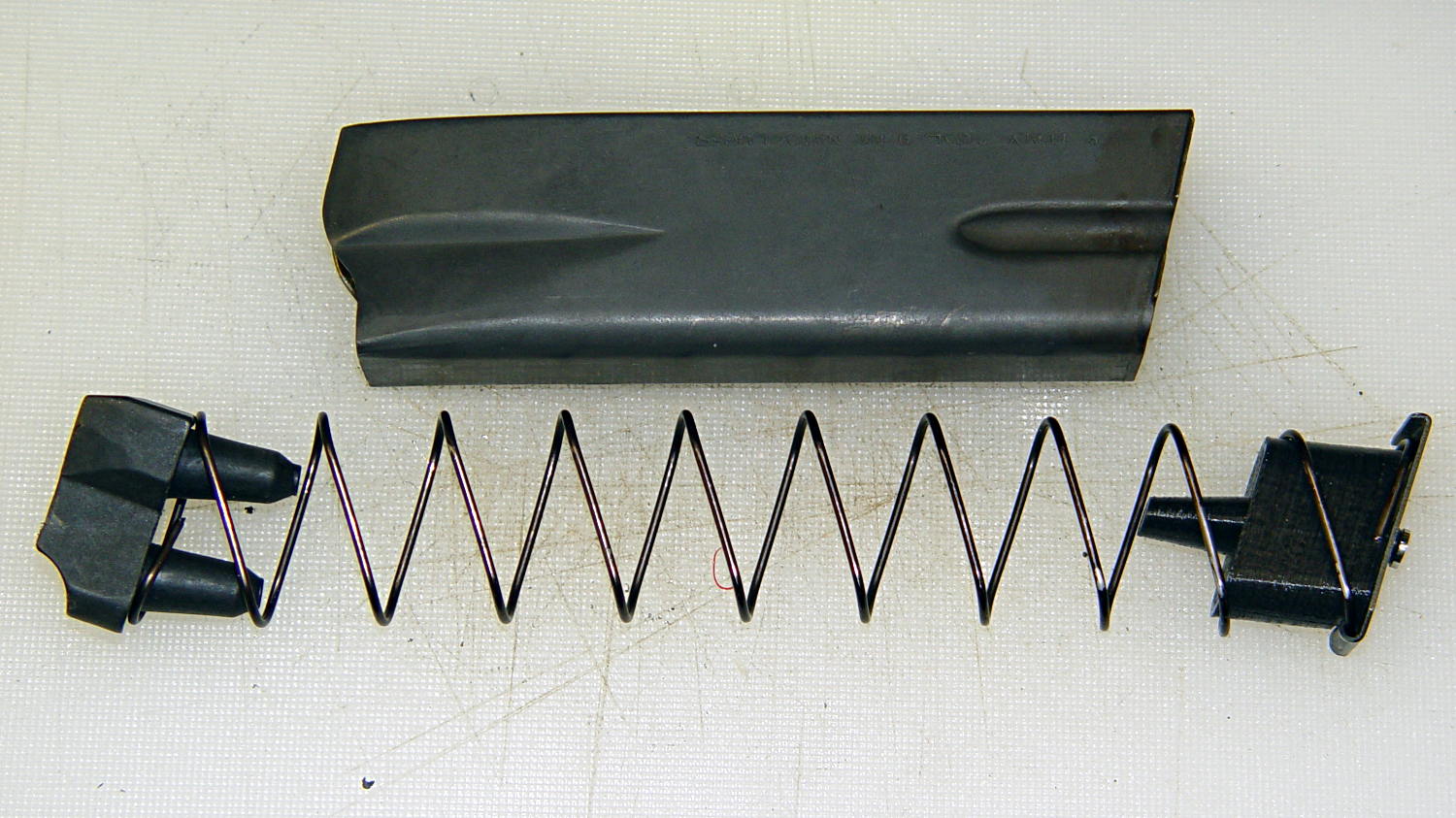
Based on tweaking the measurements from the nut trap block trial, this block attaches to the inner floor plate of the magazine and reduces the magazine’s capacity to 10 rounds:
The horn fits between the follower’s pegs, so that chopping the pegs off won’t increase the magazine’s capacity. Chopping the horn off without modifying the follower won’t make any difference, either. As nearly as I can tell, chopping the pegs off the follower will destabilize it enough that it’ll roll over atop the spring, but I admit to not actually trying that.
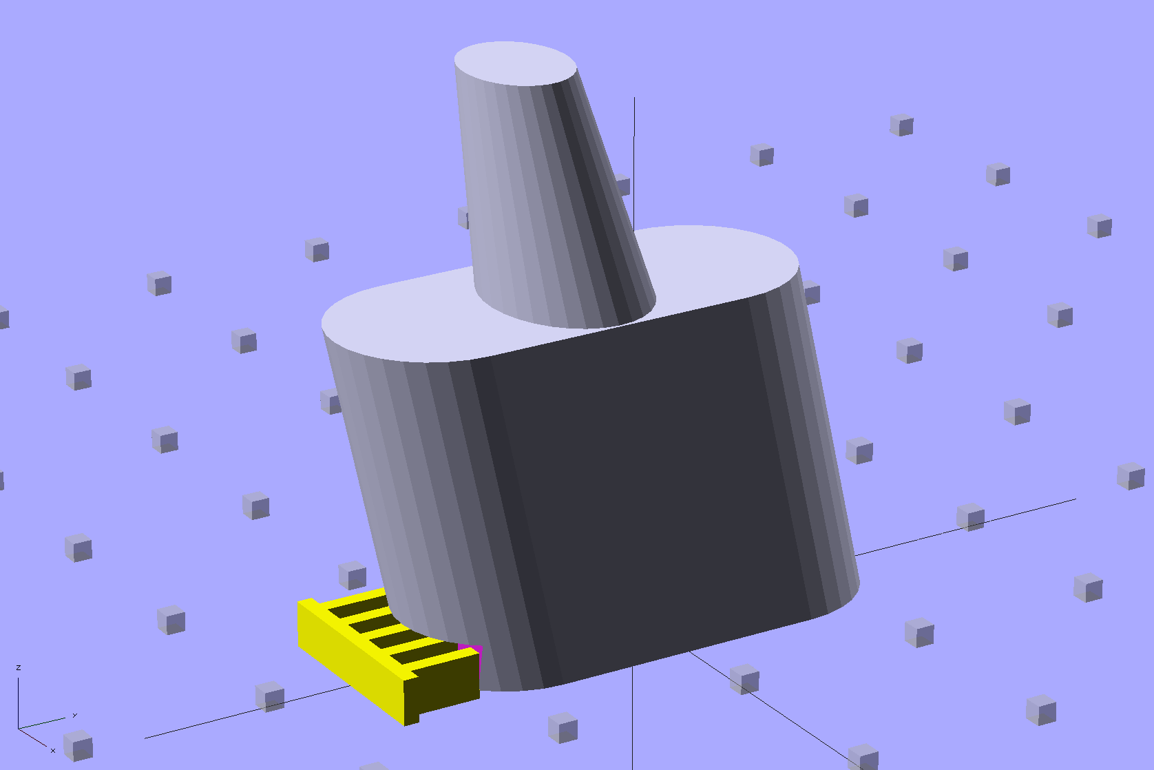
The yellow comb supports the overhang that captures the tab around the magazine spring and there’s a tiny support spider inside the lower nut clearance that holds the ceiling in place:

The inner nut trap probably droops a bit without any support, but there’s no way to tell when it’s printed as one solid piece. That trap will hold the blob of steel-filled epoxy that secures the screw and helps prevent the block from turning, so it’s not really a nut trap and doesn’t require a precision fit. The vent tube from the top of the screw shaft gives the air and any excess epoxy an exit path.
Here’s a bottom view of two blocks, showing the support structures and the results:
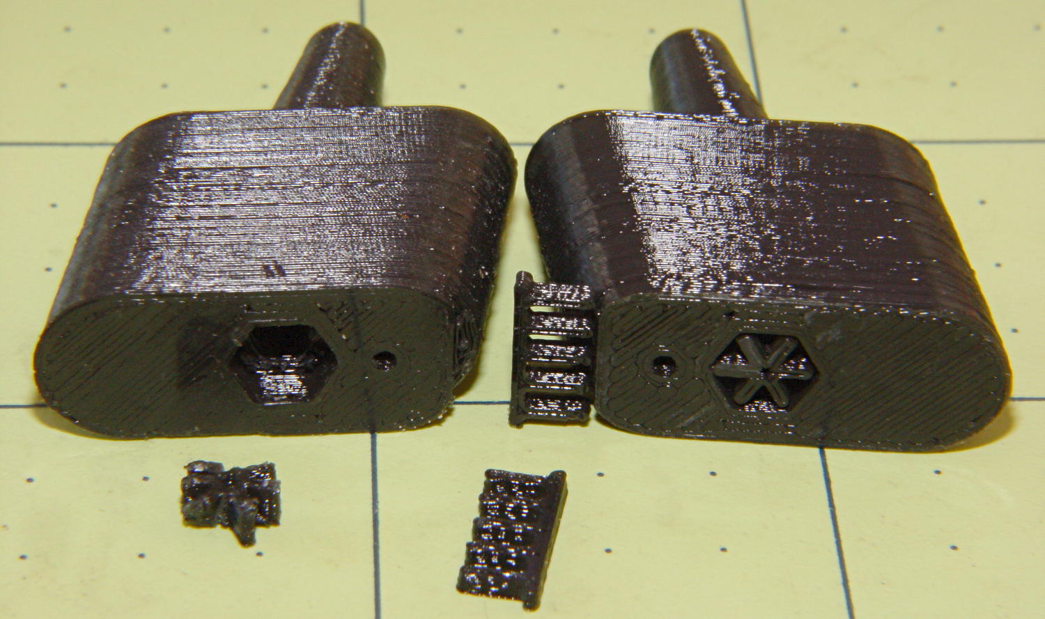
I poked the tips of a snap ring pliers into the spider and twisted it out. The comb snaps off with fingernail pressure.
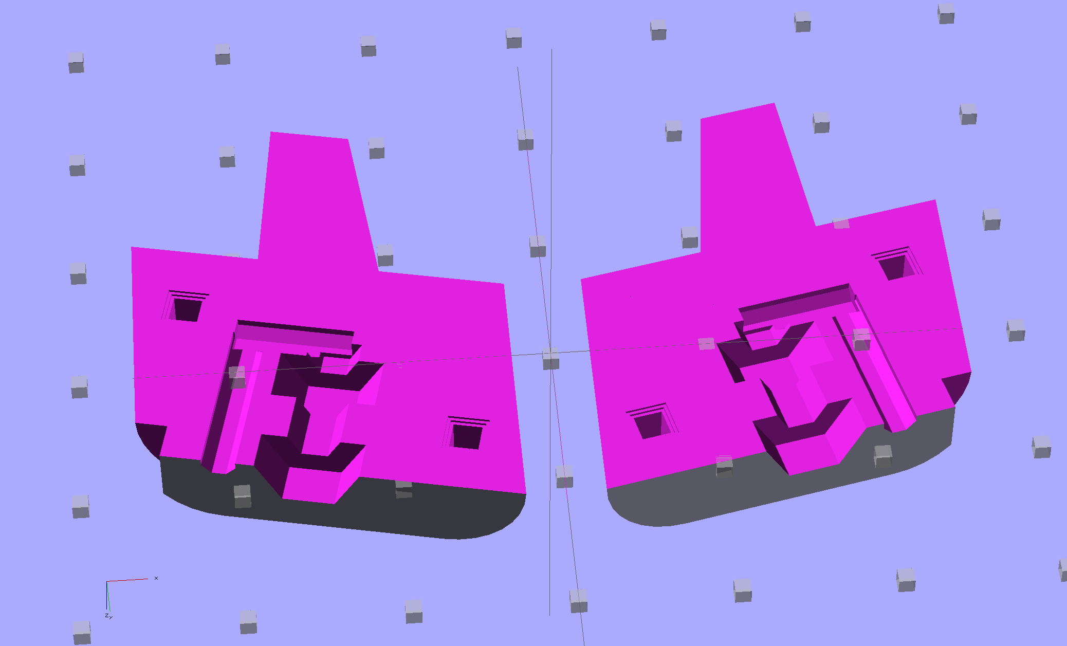
You could also print it without support by laying it flat, then glue the halves together with alignment pins. This is a bottom view:
The OpenSCAD program has a handful of configuration settings that determine which of those blocks it produces, which components appear, and how it’s oriented.
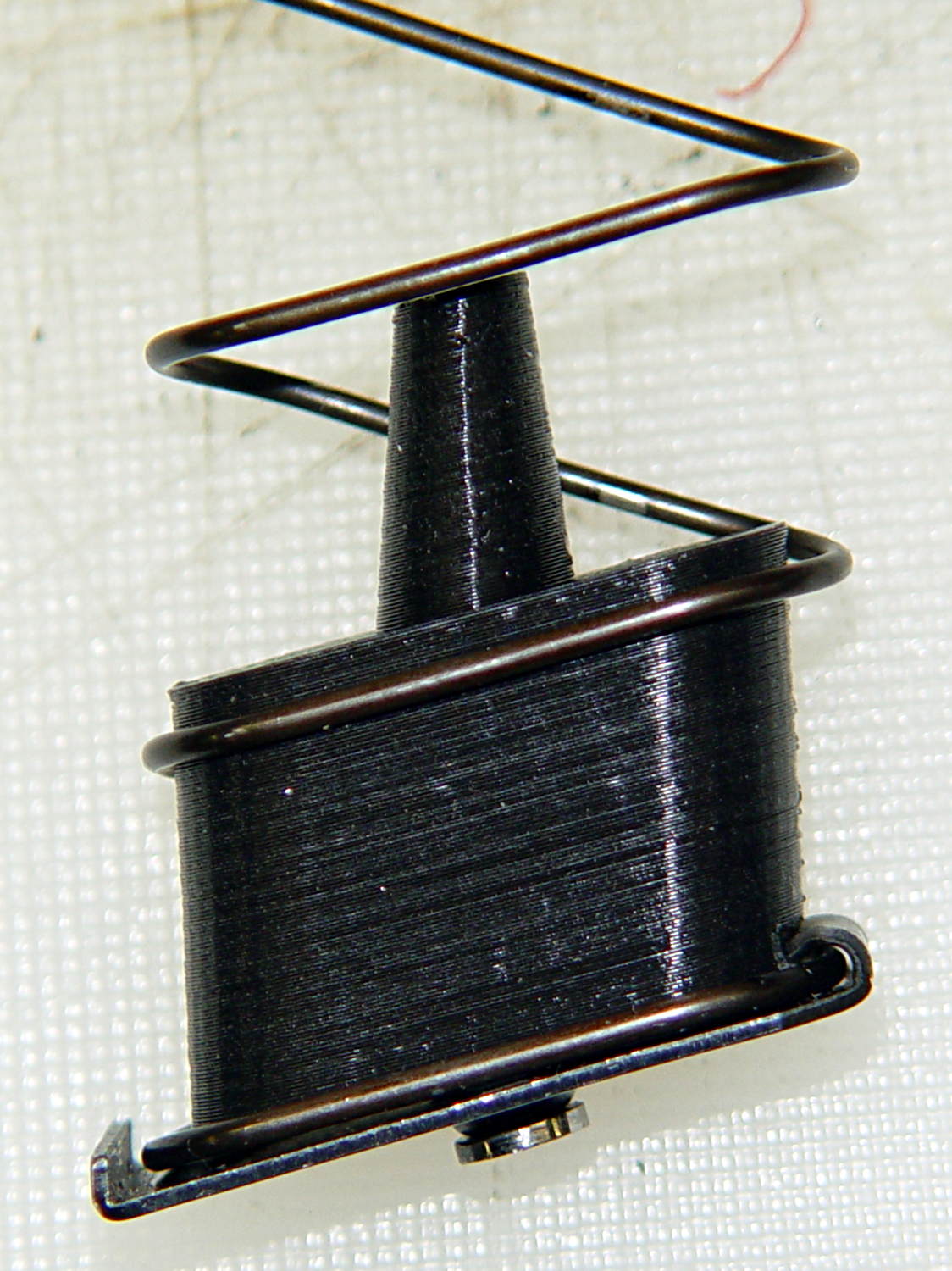
Installed in a Browning magazine, the block looks like this:
A detail of the bottom shows the notch capturing the spring tab:
I think the top surface would benefit from a small bevel to ease the spring around the block, but that’s in the nature of fine tuning.
Not having heard back from my legislators yet, I still don’t know whether this counts as a readily reversible modification. I have my doubts, what with it being plastic and all, but we shall see.
The OpenSCAD source code:
// Browning Hi-Power Magazine Block
// Ed Nisley KE4ZNU December 2013

Layout = "Whole";			// Show Whole Split
							//  Show = section view for demo, not for building
							//  Whole = upright for steel or plastic
							//  Split = laid flat for plastic show-n-tell assembly

AlignPins = (Layout == "Split");					// pins only for plastic show-n-tell

Support = (Layout != "Split");						// no support for split

//- Extrusion parameters must match reality!
//  Print with 2 shells and 3 solid layers

ThreadThick = 0.15;
ThreadWidth = 0.40;

HoleWindage = 0.2;

Protrusion = 0.1;			// make holes end cleanly

//----------------------
// Dimensions

Angle = 12.5;				// from vertical

SpringID = 10.3;			// magazine spring curvature (measure with drill shank)
SpringRadius = SpringID / 2;

Length = 24.0;				// front-to-back perpendicular to magazine shaft
Height = 18.0;				// bottom-to-top, parallel to magazine shaft
							//  18 = 10 round capacity

RectLength = Length - SpringID;	// block length between end radii

HornBaseOD = 8.0;			// fits between follower pegs to prevent shortening
HornTipOD = 5.0;
HornAddTip = (HornTipOD/2)*tan(Angle);
HornAddBase = (HornBaseOD/2)*tan(Angle);
HornAddLength = HornAddTip + HornAddBase + 2*Protrusion;
HornLength = 12.0;			// should recompute ODs, but *eh*

TrimHeight = 2.5;			// vertical clearance for spring clip on base plate
							//   OEM = 2.5
							//   generic A = 2.5

TrimInset = 1.5;			// ... horizontal
							//	 OEM = 0.0
							//   generic A = 1.5

ScrewOD = 3.0 - 0.25;		// screw hole dia - minimal thread engagement
ScrewLength = 11.0;
ScrewOffset = -1.5;			//   ... from centerline
							//  OEM = 0.0
							//  generic A = -1.5

NutOD = 5.6;				// hex nut dia across flats
NutThick = 2.4;				//  ... then add 50% to trap for thread engagement & epoxy
NutOffset = 6.0;			//  ... base height from floor

VentDia = 2.0;				// air vent from back of screw recess

PinOD = 1.72;				// alignment pins
PinLength = 6.0;
PinInset = 0.6*SpringRadius;	// from outside edges
echo(str("Alignment pin length: ",PinLength));

NumSides = 8*4;				// default cylinder sides

Offset = 5.0/2;				// from centerline for build layout

//----------------------
// Useful routines

function Delta(a,l) = l*tan(a);				// incremental length due to angle

// Locating pin hole with glue recess
//  Default length is two pin diameters on each side of the split

module LocatingPin(Dia=PinOD,Len=0.0) {

	PinLen = (Len != 0.0) ? Len : (4*Dia);

	translate([0,0,-ThreadThick])
		PolyCyl((Dia + 2*ThreadWidth),2*ThreadThick,4);

	translate([0,0,-2*ThreadThick])
		PolyCyl((Dia + 1*ThreadWidth),4*ThreadThick,4);

	translate([0,0,-(Len/2 + ThreadThick)])
		PolyCyl(Dia,(Len + 2*ThreadThick),4);

}

module PolyCyl(Dia,Height,ForceSides=0) {			// based on nophead's polyholes

  Sides = (ForceSides != 0) ? ForceSides : (ceil(Dia) + 2);

  FixDia = Dia / cos(180/Sides);

  cylinder(r=(FixDia + HoleWindage)/2,
           h=Height,
	   $fn=Sides);
}

module ShowPegGrid(Space = 10.0,Size = 1.0) {

  Range = floor(50 / Space);

	for (x=[-Range:Range])
	  for (y=[-Range:Range])
		translate([x*Space,y*Space,Size/2])
		  %cube(Size,center=true);

}

//----------------------
// The magazine block

module Block(SectionSelect = 0) {

CropHeight = Height*cos(Angle);				// block height perpendicular to base
echo(str("Perpendicular height: ",CropHeight));

	difference() {
		union() {
			intersection() {
				rotate([Angle,0,0])
					hull() {
						for (i=[-1,1])
							translate([0,i*RectLength/2,-((Length/2)*sin(Angle) + Protrusion)])						cylinder(r=SpringRadius,
										h=(Height + 2*(Length/2)*sin(Angle) + 2*Protrusion),
										$fn=NumSides);
					}
				translate([0,0,CropHeight/2])
					cube([2*SpringID,3*Length,CropHeight],center=true);
			}
			translate([0,-Height*sin(Angle),Height*cos(Angle)])
				resize([SpringID,0,0])
					intersection() {
						rotate([Angle,0,0])
							translate([0,0,-(HornAddBase + Protrusion)])
								cylinder(r1=HornBaseOD/2,
										r2=HornTipOD/2,
										h=(HornLength + HornAddLength + Protrusion),
										$fn=NumSides);
					cube([2*SpringID,Length,2*(HornLength*cos(Angle) + Protrusion)],center=true);
				}
		}

		translate([0,ScrewOffset,-Protrusion])		// screw
			rotate(180/6)
				PolyCyl(ScrewOD,(ScrewLength + Protrusion),6);

		translate([0,ScrewOffset,NutOffset])		// nut trap in center
			rotate(180/6)
				PolyCyl(NutOD,1.5*NutThick,6);

		translate([0,ScrewOffset,-Protrusion])		// nut clearance at base
			rotate(180/6)
				PolyCyl(NutOD,(1.1*NutThick + Protrusion),6);

		translate([SpringID/2,-((Length/2)/cos(Angle) - TrimInset),-Protrusion])
			rotate(180)
				cube([SpringID,2*TrimInset,(TrimHeight + Protrusion)],center=false);

		if (AlignPins)								// alignment pins
			for (i=[-1,1])
				rotate([Angle,0,0])
				translate([0,
							(i*((Length/2)*cos(Angle) - PinInset)),
							(CropHeight/2 - i*2*PinInset)])
					rotate([0,90,0]) rotate(45 - Angle)
						LocatingPin(PinOD,PinLength);

		translate([0,(ScrewOffset - NutOD),-Protrusion])	// air vent
			rotate(180/8)
				PolyCyl(VentDia,(ScrewLength + Protrusion),8);
		translate([0,(ScrewOffset + VentDia/2),ScrewLength])
			rotate([90,0,0]) rotate(180/8)
				PolyCyl(VentDia,(NutOD + VentDia),8);

		if (SectionSelect == 1)
			translate([0*SpringID,-2*Length,-Protrusion])
				cube([2*SpringID,4*Length,(Height + HornLength + 2*Protrusion)],center=false);
		else if (SectionSelect == -1)
			translate([-2*SpringID,-2*Length,-Protrusion])
				cube([2*SpringID,4*Length,(Height + HornLength + 2*Protrusion)],center=false);

	}

	NumBars = floor((SpringID/2)/(5*ThreadWidth));

	if (Support) {									// add support structures
		for (i = [-NumBars:NumBars])
			translate([i*5*ThreadWidth,
					   -((Length/2)/cos(Angle) + TrimInset/2 + ThreadWidth),
					   (TrimHeight - ThreadThick)/2])
				color("Yellow")
				cube([(2*ThreadWidth),(3*TrimInset),(TrimHeight - ThreadThick)],center=true);

		translate([-SpringID/2,-((Length/2)/cos(Angle) + 2*TrimInset + ThreadWidth),0])
			color("Yellow")
			cube([SpringID,(2*ThreadWidth),(TrimHeight - ThreadThick)],center=false);

		translate([0,ScrewOffset,0])
			for (j=[0:5]) {
			rotate(30 + 360*j/6)
				translate([(NutOD/2 - ThreadWidth)/2,0,(1.1*NutThick - ThreadThick)/2])
					color("Yellow")
					cube([(NutOD/2 - ThreadWidth),
						  (2*ThreadWidth),
						  (1.1*NutThick - ThreadThick)],
						  center=true);
        }
	}

}

//-------------------
// Build it...

ShowPegGrid();

if (Layout == "Show")
	Block(1);

if (Layout == "Whole")
	Block(0);

if (Layout ==  "Split") {
	translate([(Offset + Length/2),Height/2,0])
		rotate(90) rotate([0,-90,-Angle])
			Block(-1);
	translate([-(Offset + Length/2),Height/2,0])
		rotate(-90) rotate([0,90,Angle])
			Block(1);
}

Comments
6 responses to “Browning Hi-Power Magazine Capacity Reduction Block”
Well, worst case, having done the design and prototyping in PLA you can now send the STL off to someone for laser metal powder sintering…
Or lost-PLA cast them yourself. :)
Stay tuned… [grin]
Why you prefer to epoxy two parts? Is press pause and put the nut inside a better way?
The two halves get solvent-bonded together, which pretty much fuses them into a single object. The epoxy fills the central shaft and inner nut trap to hold the screw in place.
I’ve never been a big fan of interrupting the process, because pausing and fiddling with the objects introduces a whole bunch of uncontrollable factors.
Although I did some trials with gluing split blocks around actual nuts to see how the idea worked, I think epoxy-filling the void in a one-piece block will suffice. After all, it’s supposed to be a non-removable screw!
[…] A trial fit shows it captures the spring tab just like the plastic version did: […]
[…] on the idea of reducing a magazine’s capacity by installing a not “readily” modifiable(*) block, brazing an M3 nut to a magazine […]