Ed Nisley's Blog: Shop notes, electronics, firmware, machinery, 3D printing, laser cuttery, and curiosities. Contents: 100% human thinking, 0% AI slop.
A recent quilt photo shoot degenerated into me chasing several bright orange clamp jaws across the deck as they popped off their clamps hanging from the photo backdrop scaffold. Most clamps have jaws snapping onto actual rods, but these clamps have molded-in-place “rods” much smaller than the 2 mm expected by the jaws and much more irregular than seems reasonable.
Trace and scan the nose of a clamp:
Large spring clamp nose outline
Curiously, the molded rod is not centered in the nose:
Large spring clamp nose – pin locatIon
Use LightBurn to coerce a scan of the first sketch into a suitable path, laser-cut some MDF, and glue up a drill fixture:
Spring clamp jaw pins – fixture gluing
Align the drill to the center of the off-center hole marked on the bottom layer:
Spring clamp jaw pins – drill alignment
The drilling setup looks casual, but hand-holding the clamps against the rear wall and into the form-fitting nose recess sufficed:
Spring clamp jaw pins – fixture overview
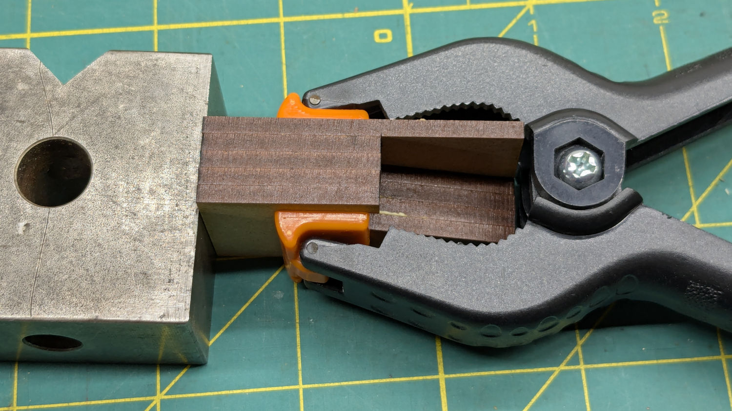
I snipped the plastic “rods” out before drilling the holes, then rammed 2 mm steel rods in place:
Spring clamp jaw pins – steel
They’re really 5/64 inch = 1.98 mm rods from the oil-hardening drill rod stash, but entirely sufficient for the purpose.
With one clamp in hand, though, there was obviously no reason for the rods to be off-center. So I centered the drill in the nose, punctured the rest of the clamps, and pressed 2 mm carbon fiber rods in place:
Spring clamp jaw pins – steel vs carbon fiber
The rods were cut to 20 mm by rolling them across a pad with firm pressure from a utility knife. That was mostly to get some experience cutting carbon fiber, which is obviously overqualified for the job.
Snap the orange jaws in place and I shall never suffer the embarrassment of chasing them again …
A confluence of unrelated events led me to unboxing and setting up the CNC-3018XL most recently used to plot Homage Tek Circuit Computer decks, but the table slid along its rods entirely too easily. A peek at the leadscrew revealed an assortment of parts last seen when I extended the frame:
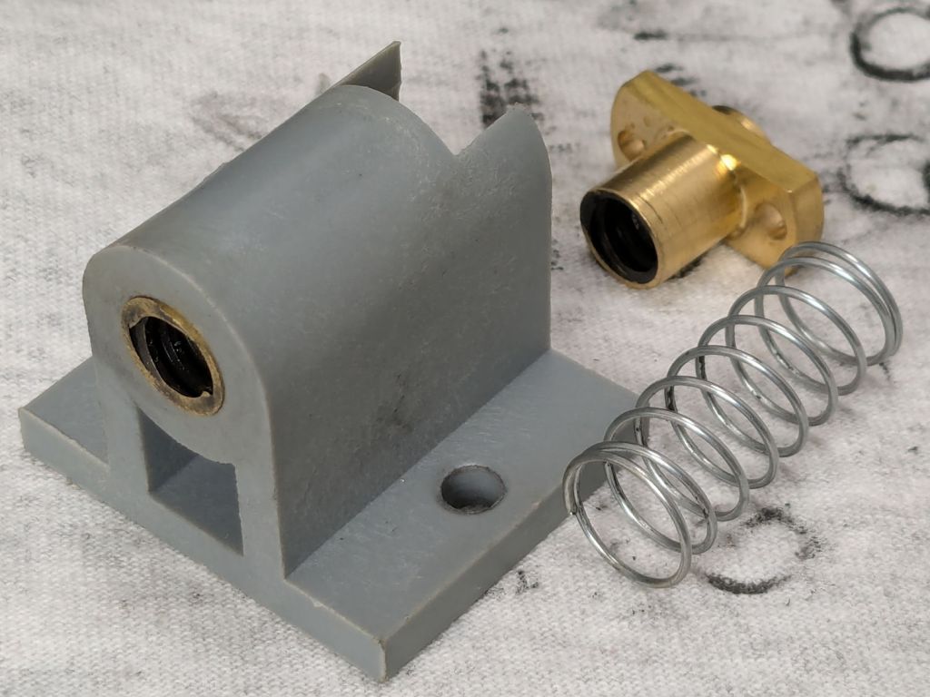
3018CNC – table drive – as found
The featureless cylinder is the leadscrew follower nut, which evidently popped out of its proper place in the table drive block:
3018CNC – table drive parts
The crude chamfer suggests that end went into the block first, so that’s what I did:
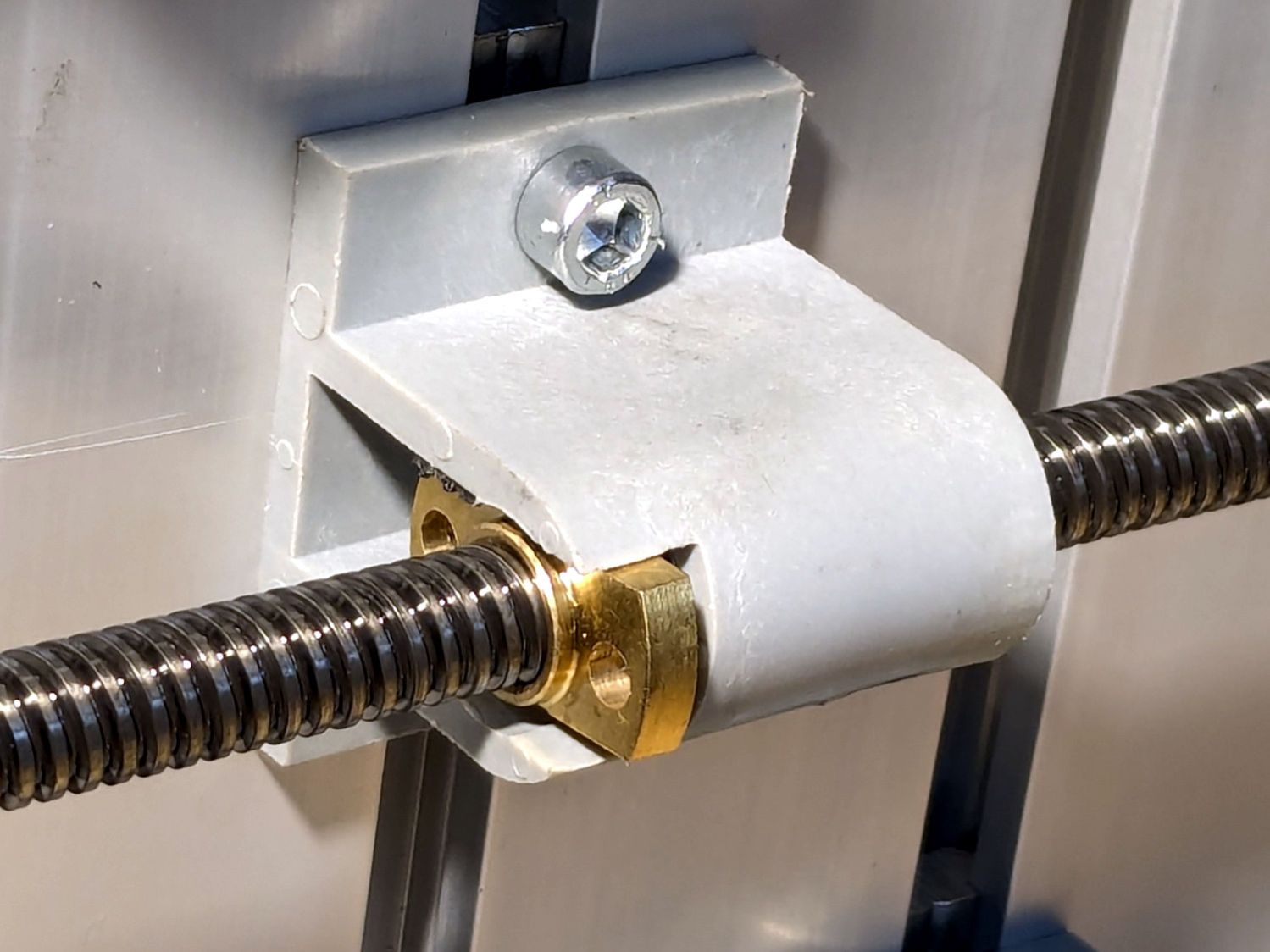
3018CNC – table drive – follower nut installed
It seems snug enough in there, at least for a machine used solely for plotting and maybe drag knife cuttery, so I’ll assume the box received some rough handling during our move.
It’s now back in place and seems to work well enough:
3018CNC – table drive – installed
I briefly considered adding some setscrews to hold it in place, but came to my senses. If it pops out again, maybe it’ll be time to rebuild that block with proper retention.
The software side of the thing surely needs TLC, too.
For reasons I do not profess to understand, GIMP 3.0 does not work with plugins written for GIMP 2.0, including the XSane plugin that handles scanning. This seems like an obvious oversight, but after three months it also seems to be one of those things that’s like that and that’s the way it is.
It turns out gimp-xsanecli tells XSane to output the filename it’s using, then expects to find the identifying XSANE_IMAGE_FILENAME string followed by the filename on the first line of whatever it gets back:
if result != 'XSANE_IMAGE_FILENAME: ' + png_out:
  Gimp.message('Unexpected XSane result: ' + result)
  return Gimp.ValueArray.new_from_values([GObject.Value(Gimp.PDBStatusType, Gimp.PDBStatusType.EXECUTION_ERROR)])
The font ligature that may or may not mash != into ≠ is not under my control.
Protracted poking showed the scanner fires a glob of HTML through proc/stdout into gimp-xsaneclibefore XSane produces its output, but after the scan completes:
<!DOCTYPE HTML PUBLIC "-//W3C//DTD HTML 4.01//EN "
"http://www.w3.org/TR/html4/strict.dtd">
<html>
<head>
… snippage …
</head>
<body><noscript>Enable your browser's JavaScript setting.</noscript></body></HTML>XSANE_IMAGE_FILENAME: /tmp/out.png
Complicating the process:
The HTML glob only appears on the first scan, after which XSane produces exactly what gimp-xsanecli expects
There is no newline separating the glob from the expected output on the last line
So …
Insert a while loop into the main loop to strip off the HTML glob line by line by line:
        while True:
                # Wait until XSane prints the name of the scanned file, indicating scanning is finished
                # This blocks Python but that is ok because GIMP UI is not affected

                # discard HTML header added by scanner to first scan
                while True :

                        result = proc.stdout.readline().strip()

                        if r'</body>' in result :
                                result = result.partition(r'</HTML>')[-1]
                        #        Gimp.message('Found end of HTML: ' + result)
                                break

                        elif 'XSANE_IMAGE_FILENAME:' in result :
                        #        Gimp.message('Found filename: ' + result)
                                break

                        else :
                        #        Gimp.message('Discarding: ' + result)
                                continue

                if result == '':
                        # XSane was closed
                        break

                if result != 'XSANE_IMAGE_FILENAME: ' + png_out:
                        Gimp.message('Unexpected XSane result: ' + result)
                        return Gimp.ValueArray.new_from_values([GObject.Value(Gimp.PDBStatusType, Gimp.PDBStatusType.EXECUTION_ERROR)])

                # Open image
                image = Gimp.file_load(Gimp.RunMode.NONINTERACTIVE, Gio.File.new_for_path(png_out))
                Gimp.Display.new(image)

                # Remove temporary files
                os.unlink(png_out)

                if not SCAN_MULTIPLE:
                        proc.terminate()
                        break

        os.rmdir(tempdir)

        return Gimp.ValueArray.new_from_values([GObject.Value(Gimp.PDBStatusType, Gimp.PDBStatusType.SUCCESS), GObject.Value(Gimp.Image.__gtype__, image)])
While it’s tempting to absorb the whole thing in one gulp with proc.stdout.read().strip(), that doesn’t work because nothing arrives until the XSane subprocess terminates, which is not what you want.
A scan to show It Just Works™ :
I expect it doesn’t work under a variety of common conditions, but … so far so good.
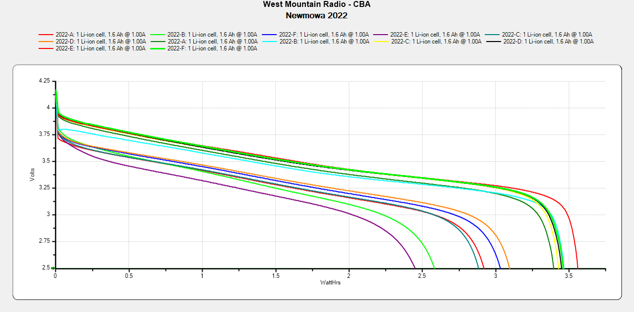
The best four have a capacity down 14% from the good old days and the weakest pair are down 29%.
The camera uses 1.9 W, so a battery with 2.5 W·hr capacity should last 78 minutes, but about 400 mV of voltage depression causes the camera to give up before using its full capacity.
So they have a useful lifetime of maybe two years in our regular bike riding schedule and I should have bought replacements last year. I hope the next batch isn’t New Old Stock or recycled cells.
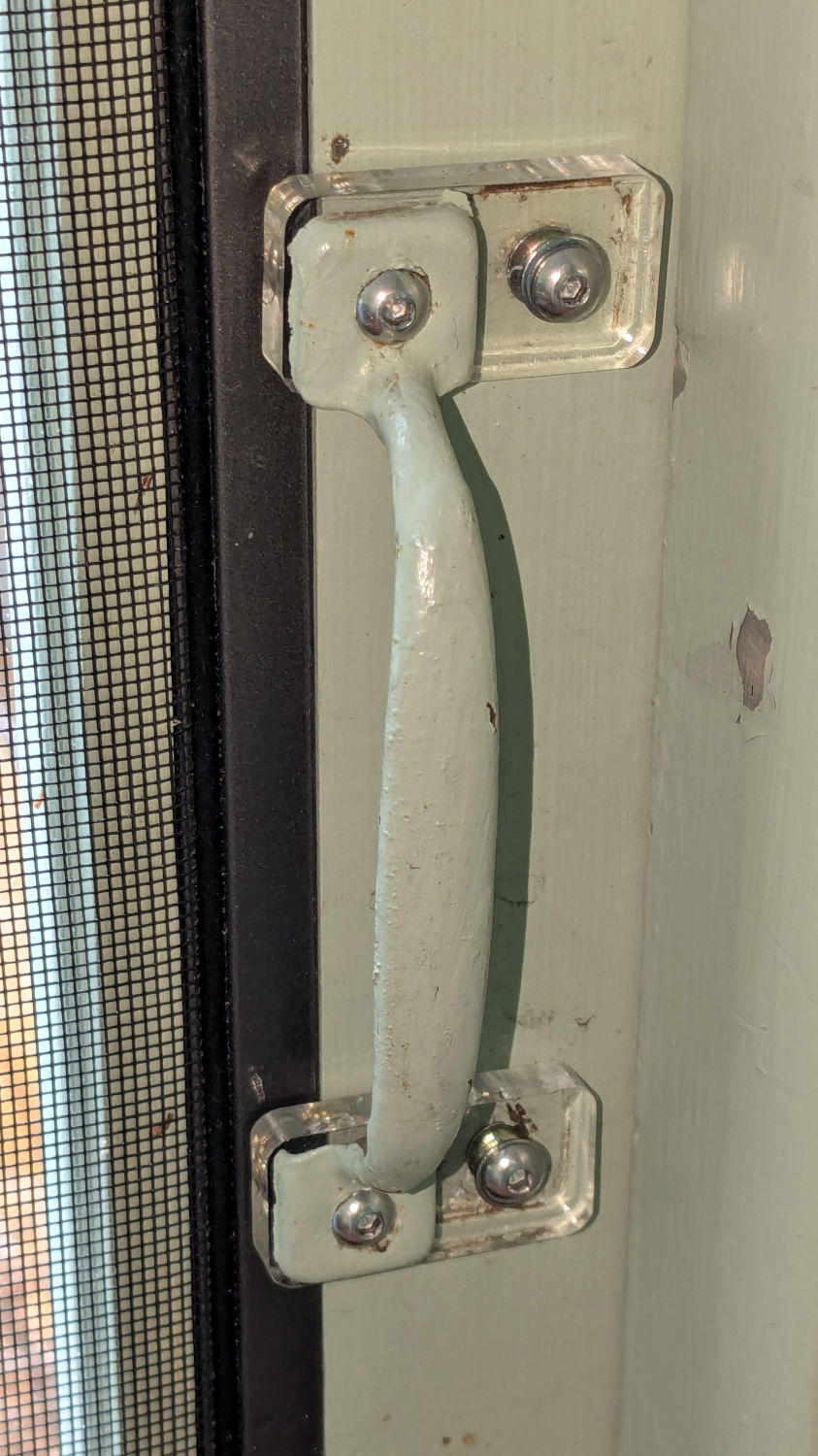
For unknown reasons, the handle on the porch screen door was installed less than one finger width from the frame, so I conjured a pair of plastic plates shifting it far enough to prevent finger pinches and avoid the screws for the outside handle:
Porch door handle repositioning
The original holes now have M4 threaded wood inserts and the holes in the ¼ inch acrylic have M4 heat-staked brass inserts, mostly because I had everything on hand.
This was part of a project to trim the bottom of the door to clear the porch floor boards, which evidently continued warping after they trimmed the door to fit:
Porch door trimming
That thin blue line suggests the highest part of the floor was once near the bottom of the picture, but it’s now the lowest part. The highest part is now near the hinge side near the top of the picture, firmly jamming the door in place.
The power supply converting the battery’s raw 6 V into whatever voltage is required by my troublesome SJCAM M50 trail camera failed, despite the replaced wire between the battery and the camera remaining intact. The camera continued to work with 5 V power supplied through its USB-C jack, so I think it can accomplish most of its goals with a USB battery pack nearby.
Unfortunately, the USB-C jack isn’t accessible with the case closed, so I decided to repurpose the battery compartment’s external 6 V input jack.
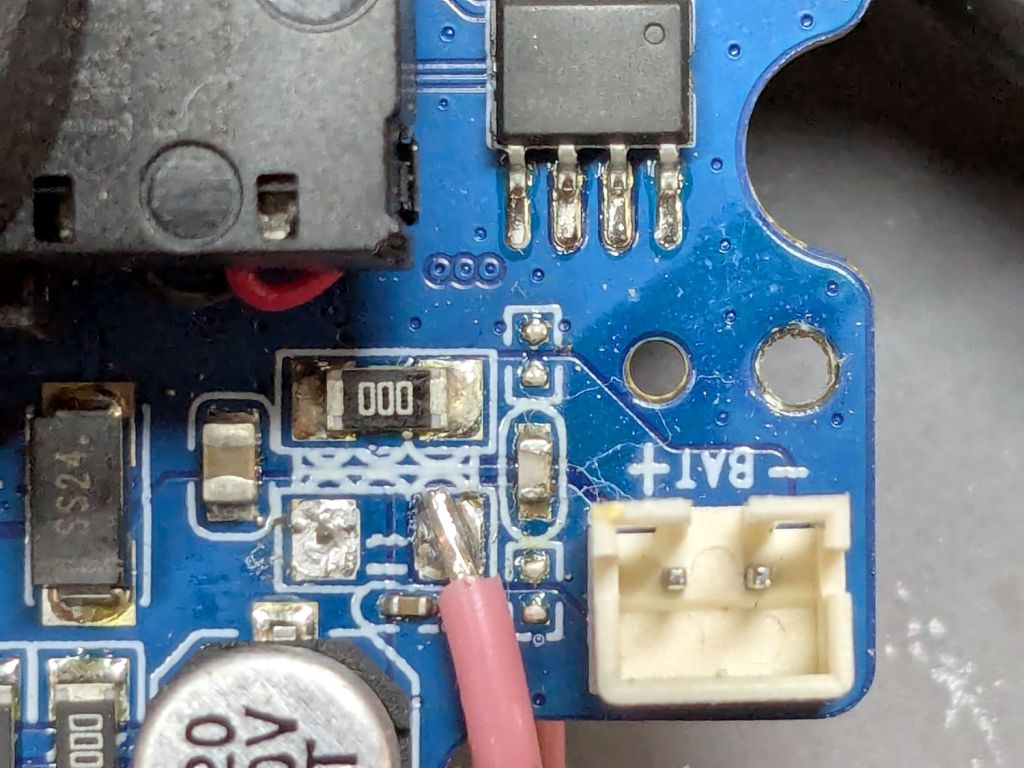
I removed the 000 (0 Ω) SMD “resistor” connecting the battery + terminal to the power supply circuitry and soldered one end of a wire to that pad:
SJCAM M50 – battery input pad
The adjacent 000 “resistor” connects the battery - input terminal to the circuit, so it remains in place.
The other end of the wire goes to the high side of the +5 V filter caps for the USB-C input:
SJCAM M50 – USB power input pad
The battery pack produced 6 V from two parallel-ish banks of four AA cells or an external source arriving through a 3.5 / 1.35 mm coaxial power plug, with a Schottky diode dropping 250 mV before reaching the BAT connector in the first picture. The camera seems happy to run from slightly under 5 V.
Unfortunately, “happy to run” means the camera remains in Setup mode, ready to dump its stored images through the USB port, and won’t take pictures regardless of the switch normally controlling such things. It seems I must either troubleshoot the switching regulator generating the internal power supply voltage(s)or junk the camera.
I’m not red-hot pleased with the several SJCAM cameras I’ve used, as they seem to feature under-designed durability for their intended use. The fact that SJCAM cameras seem to be on the better side of a bad lot is not comforting.
I did the probing & doodling during a Squidwrench remote meeting and was assured I would not regret directly applying five volts to the circuit, said with the intonation of this meme: