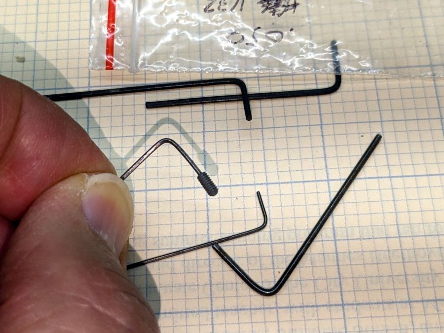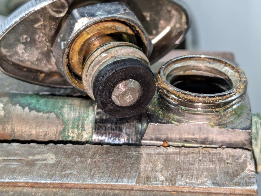
While cleaning dead bugs out of the ceiling lamps, we discovered the kitchen light was missing one of the three nuts holding its cover in place. While spare nuts might be available, this seemed like a quicker & easier solution:

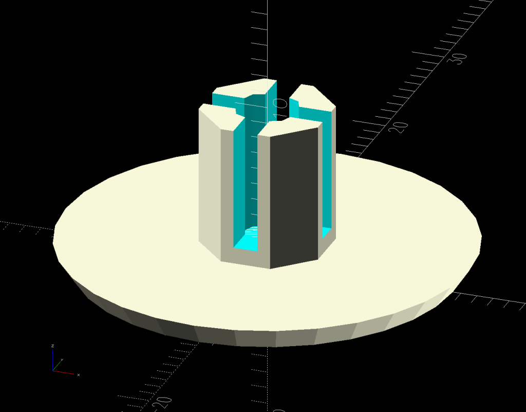
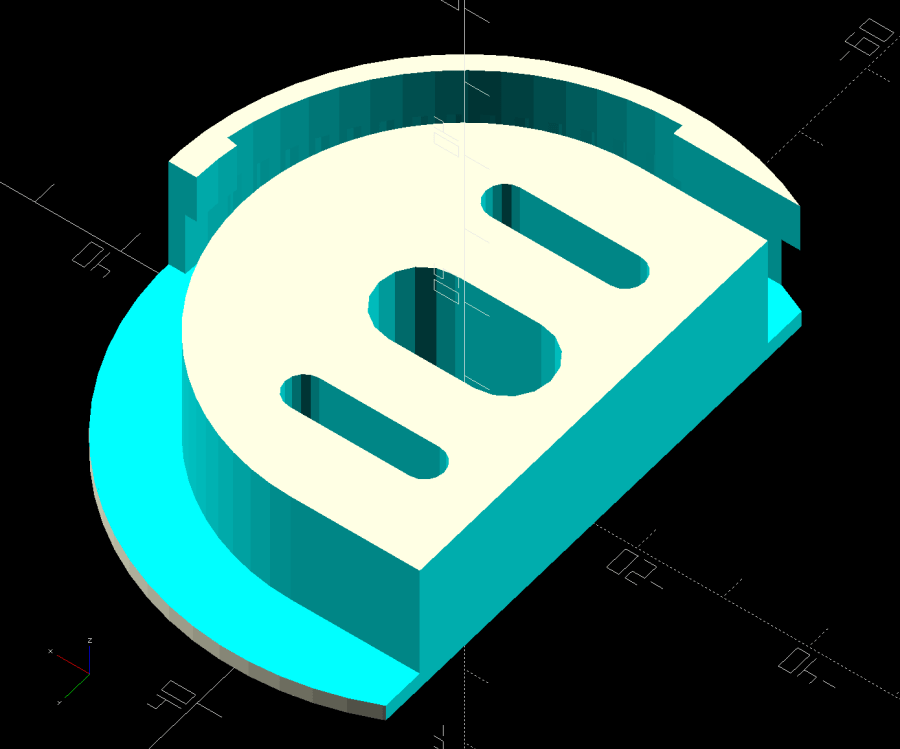
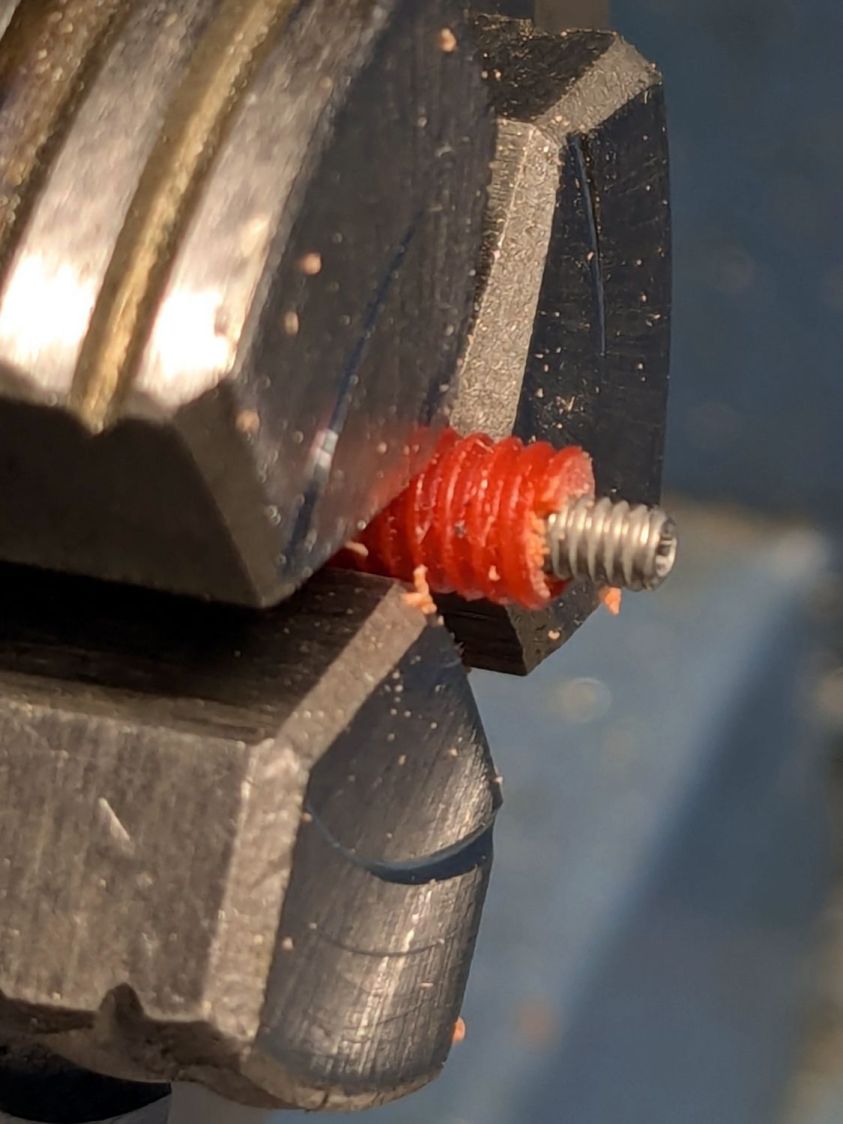
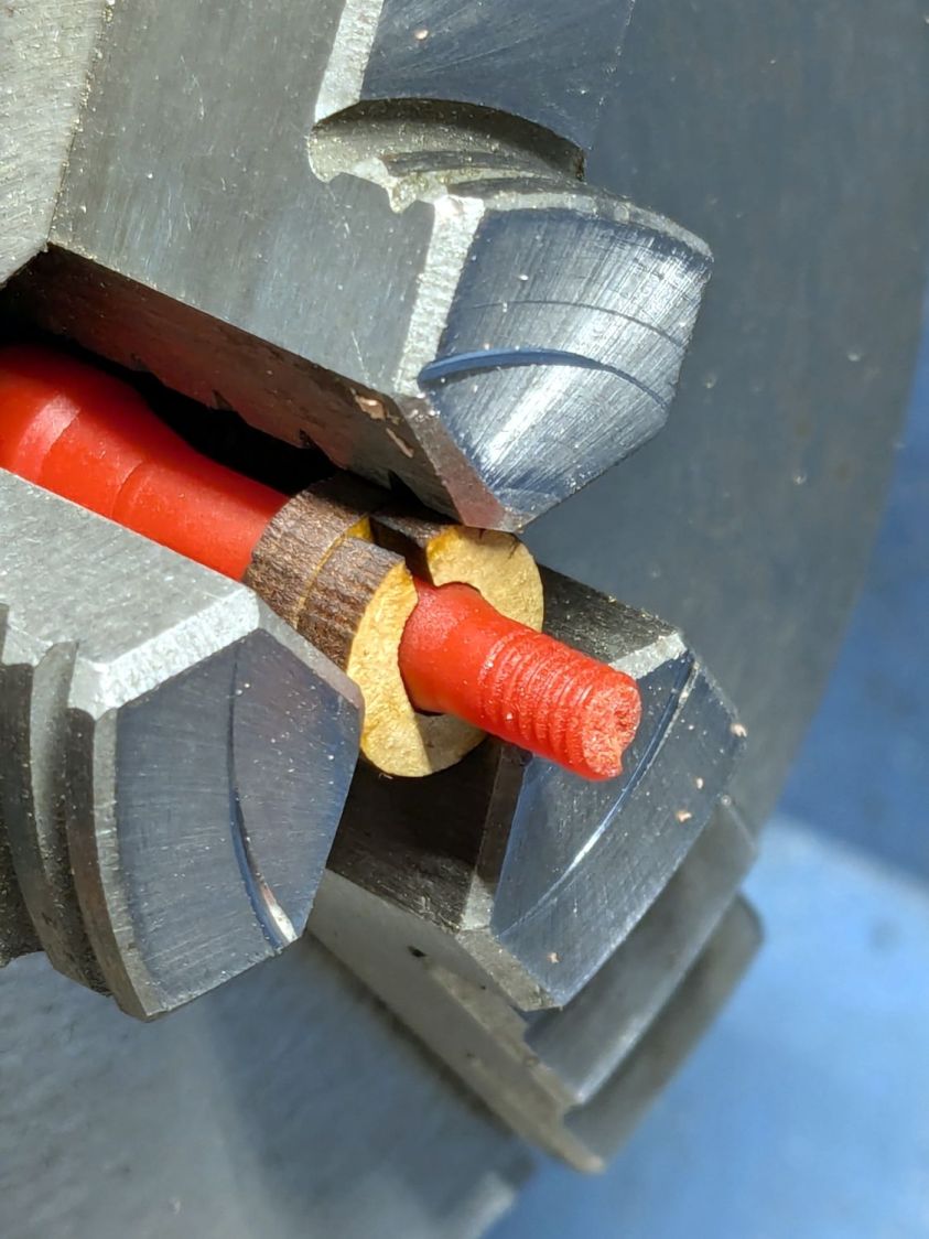
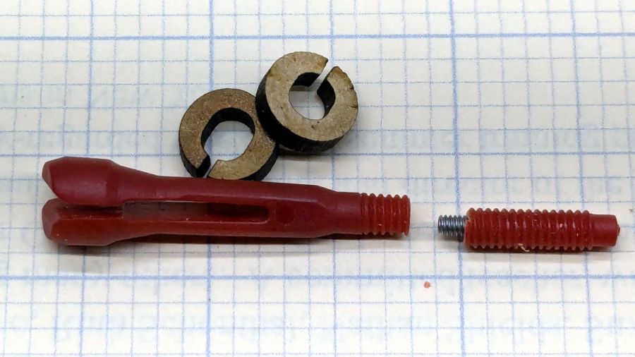
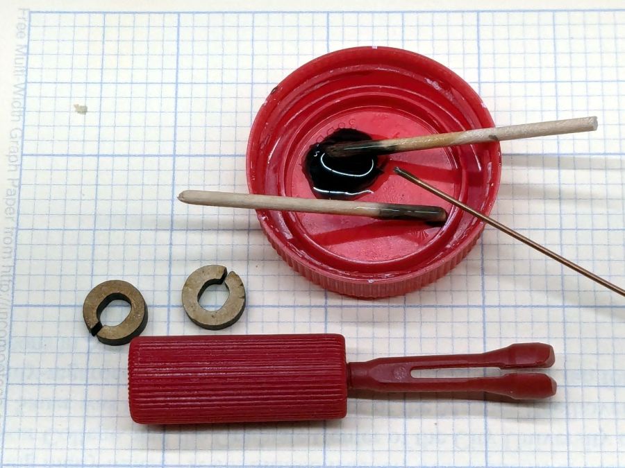
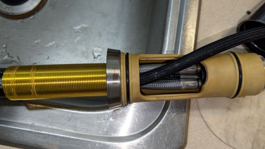
The stepped interior fits a brass insert with 8-32 threads (not metric, to my utter astonishment) rammed in place with a heat-set tool:

Using the nominal diameters seems to work fine, although I’m sure some finesse will be needed with smaller inserts.
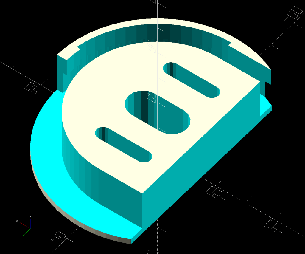
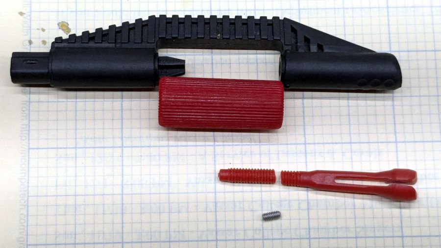
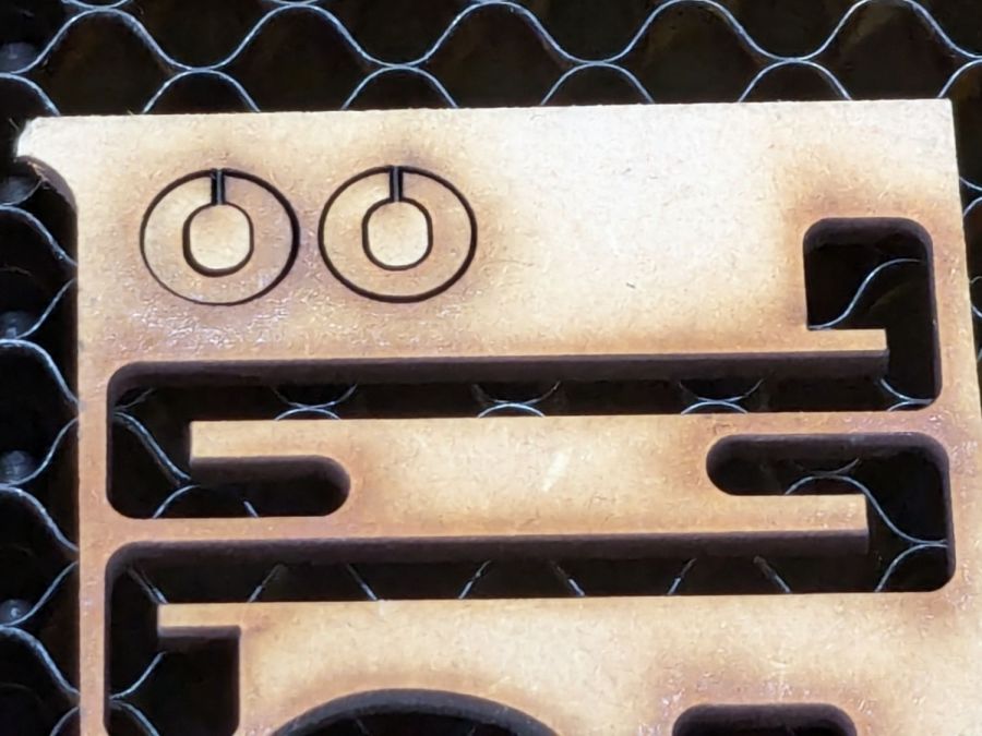
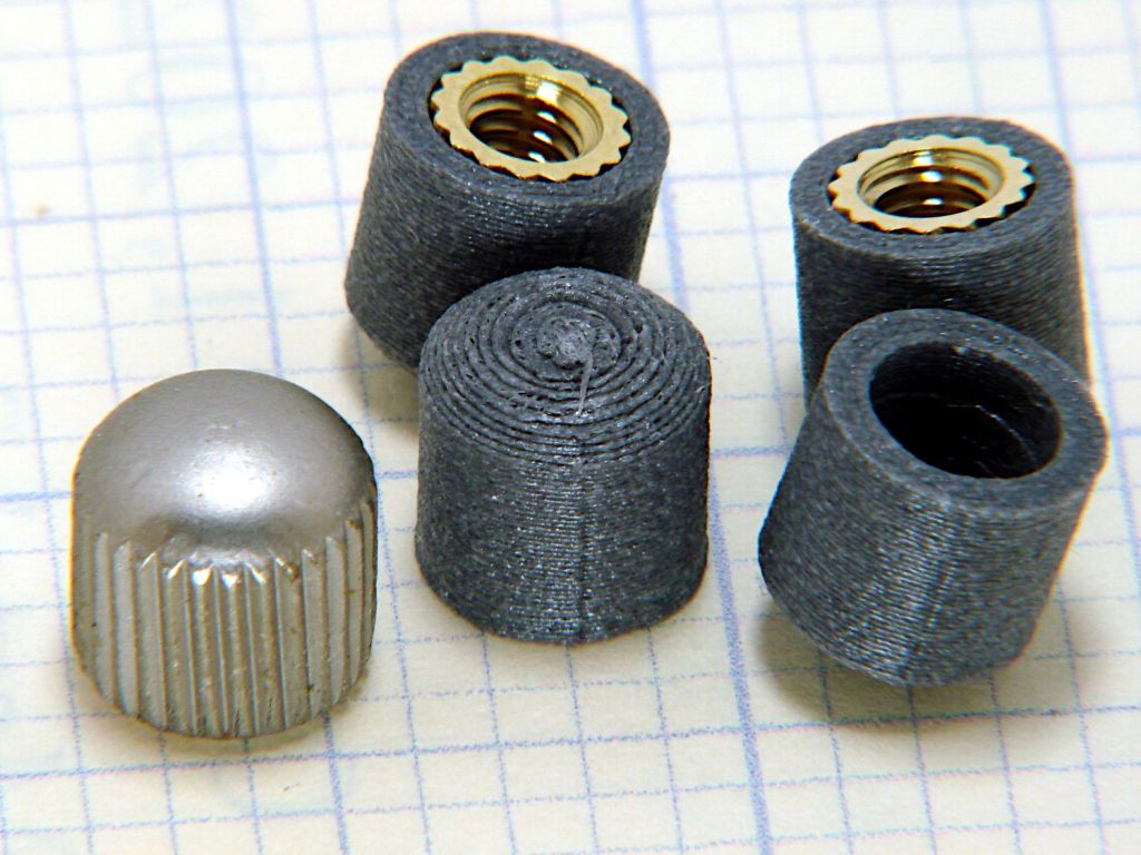
Printed four just to be sure, rammed three inserts, and they’re ready:

The curved cap matches the original nut through the use of the Chord Equation to get the cap radius as a function of its height (sagitta) & base diameter. Admittedly, it looks kinda grotty with only a dozen layers, but it’s the thought that counts.
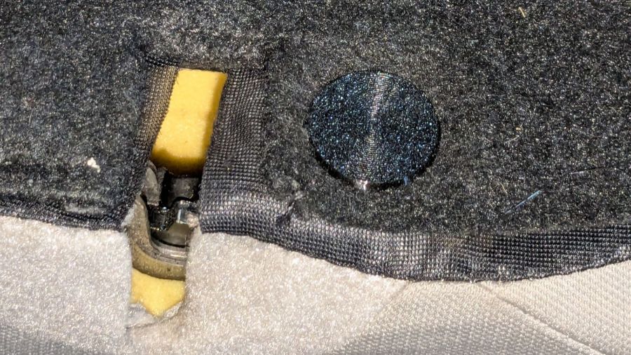
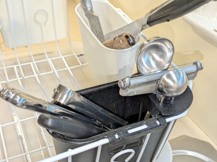
The original nuts are heavy knurled steel and the new ones are cheap plastic, but nobody will ever know:

Bonus: now I have two spare steel nuts for the next time …
The OpenSCAD source code:
// Nuts for LED ceiling light fixture
// Ed Nisley KE4ZNU
// 2024-09-27

KnurlLength = 7.4;
KnurlOD = 9.0;

CapOD = 9.0;
CapHeight = 2.0;
CapRadius = (pow(CapHeight,2) + pow(CapOD,2)/4)/(2*CapHeight);
echo(CapRadius=CapRadius);

NumSides = 1*(2*3*4);
$fn = NumSides;

Protrusion = 0.1;

difference() {
    union() {
        intersection() {
            translate([0,0,KnurlLength + CapHeight - CapRadius])
                sphere(r=CapRadius);
            translate([0,0,KnurlLength])
                cylinder(d=2*KnurlOD,h=KnurlLength);
        }

        cylinder(d=KnurlOD,h=KnurlLength);

    }

// Ad-hoc 8-32 brass insert sizes

    cylinder(d=5.5,h=8.0);
    cylinder(d=5.9,h=5.7);
    cylinder(d=6.2,h=2.2);
    translate([0,0,-Protrusion])
        cylinder(d=6.2,h=2.2);

}